Page 1194 of 1226

31 0-00-8 Fuel System - General Information 31 0-00-8
GENERAL PROCEDURES
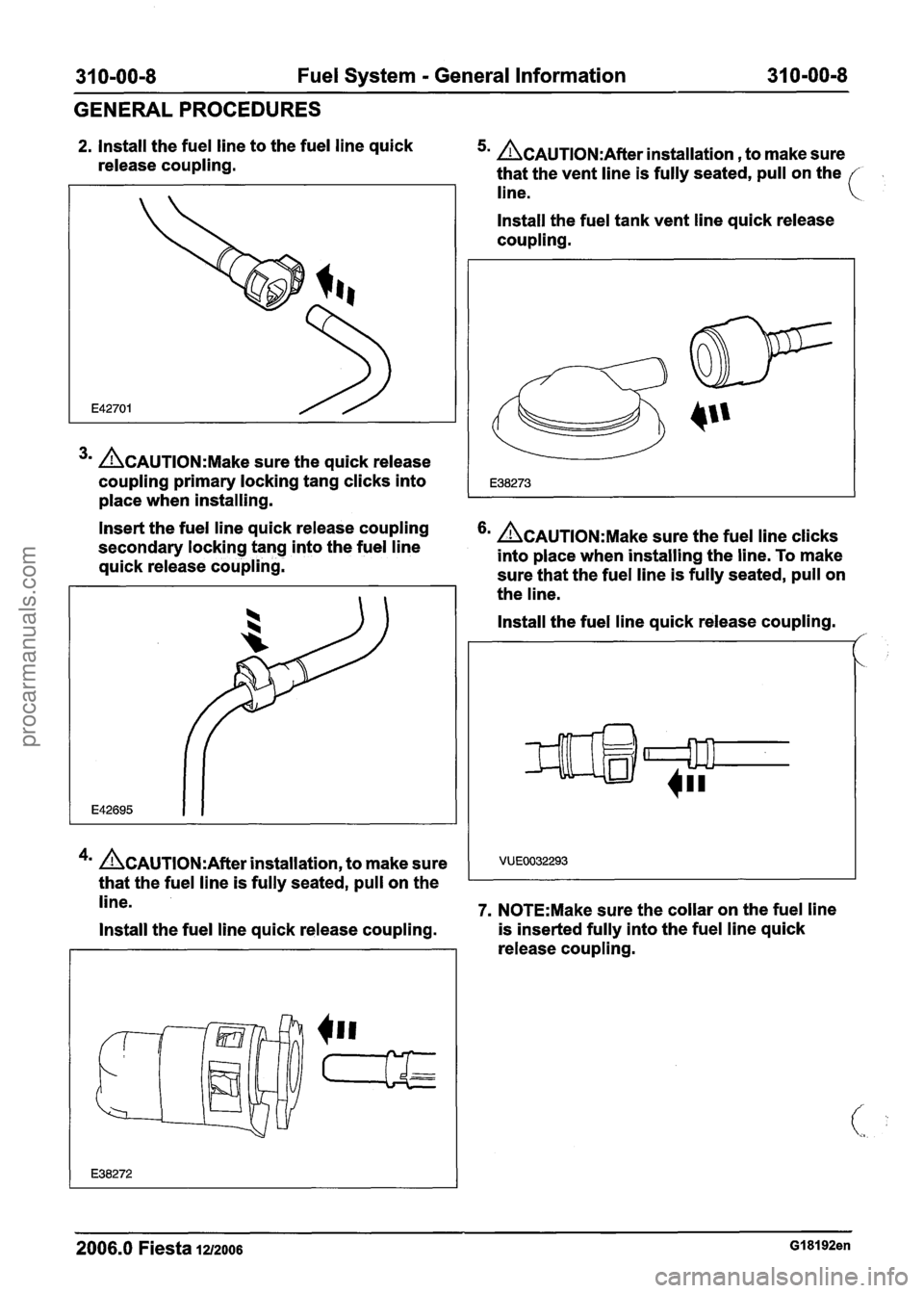
2. Install the fuel line to the fuel line quick
release coupling. 5m &AUTION:A~~~~ installation , to make sure
that the vent line is fully seated, pull on the
line.
3m &AUTION:M~~~ sure the quick release
coupling primary locking tang clicks into
place when installing. Install the fuel
tank vent line quick release
coupling.
Insert the fuel line quick release coupling
secondary locking tang into the fuel line
&AUTION:M~~~ sure the fuel line clicks
into place when installing the line. To make
quick release coupling.
sure that the fuel line is fully seated, pull on
the line.
4m &AUTION:A~~~~ installation, to make sure
that the fuel line is fully seated, pull on the Install the
fuel line quick release coupling.
/'
line. 7. N0TE:Make sure the collar on the fuel line
Install the fuel line quick release coupling. is
inserted fully into the fuel line quick
release coupling.
2006.0 Fiesta 1212006 GI 81 92en
procarmanuals.com
Page 1195 of 1226
31 0-00-9 Fuel System - General Information 31 0-00-9
GENERALPROCEDURES
Install the fuel line quick release coupling. 2. Press the fuel line quick release coupling
locking tang into position.
VUE0004016
8. N0TE:Make sure the collar on the fuel line
is inserted fully into the fuel line quick
release coupling before the locking tang is
locked.
lnstall the fuel line quick release coupling.
1. lnstall the fuel line quick release coupling
locking tang.
2. Rotate the fuel line quick release coupling
locking tang into position.
9. N0TE:Make sure the collar on the fuel line
is inserted fully into the fuel line quick
release coupling before the locking tang is
locked.
Install the fuel line quick release coupling.
I. lnstall the fuel line quick release coupling.'
2006.0 Fiesta 1212006 GI 81 92en
procarmanuals.com
Page 1200 of 1226
31 0-01 -2 Fuel Tank and Lines 31 0-01 -2
SPECIFICATIONS
Torque Specifications
Description
Nm Ib-ft I b-in I/
Fuel tank support strap retaining bolts I 25 I 18 I -
Fuel tank filler pipe retaining bolts I 9 I - I 80 I
Fuel pump module locking ring - All except vehicles
with diesel engine
Fuel level sensor locking ring
- Vehicles with diesel
engine
Floor panel crossmember
I 4 I - I 35 I
2006.0 Fiesta 1212006 GI 48228en
procarmanuals.com
Page 1207 of 1226
31 0-01 -9 Fuel Tank and Lines 31 Om01 -9
REMOVAL AND INSTALLATION
Disconnect the fuel supply and fuel return All except vehicle with diesel engine
lines from the fuel tank. For additional
I information, refer to Section 310-00 [Fuel 20. Using the special tool, loosen the fuel pump
module locking ring.
System
- General Information].
All exce~t vehicles with diesel engine 21 ACAUTION:M~~~ sure that the float or V
17. Disconnect the evaporative emissions
canister pipe.
-.
Squeeze the clip to release the pipe.
18.
Remove the evaporative emissions canister
from the fuel tank.
All vehicles
19. Remove the fuel tank assembly. arm
are not damaged while removing or
installing the fuel pump module.
Remove the fuel pump module.
I. Remove the locking ring.
2. Remove the O-ring seal.
Discard the O-ring seal.
3. Lift the module from the fuel tank.
2006.0 Fiesta IZIZOO~ GI 89084en
procarmanuals.com
Page 1208 of 1226

310-01 -1 0 Fuel Tank and Lines 31 0-01-10
REMOVAL AND INSTALLATION
Vehicles with diesel engine Installation
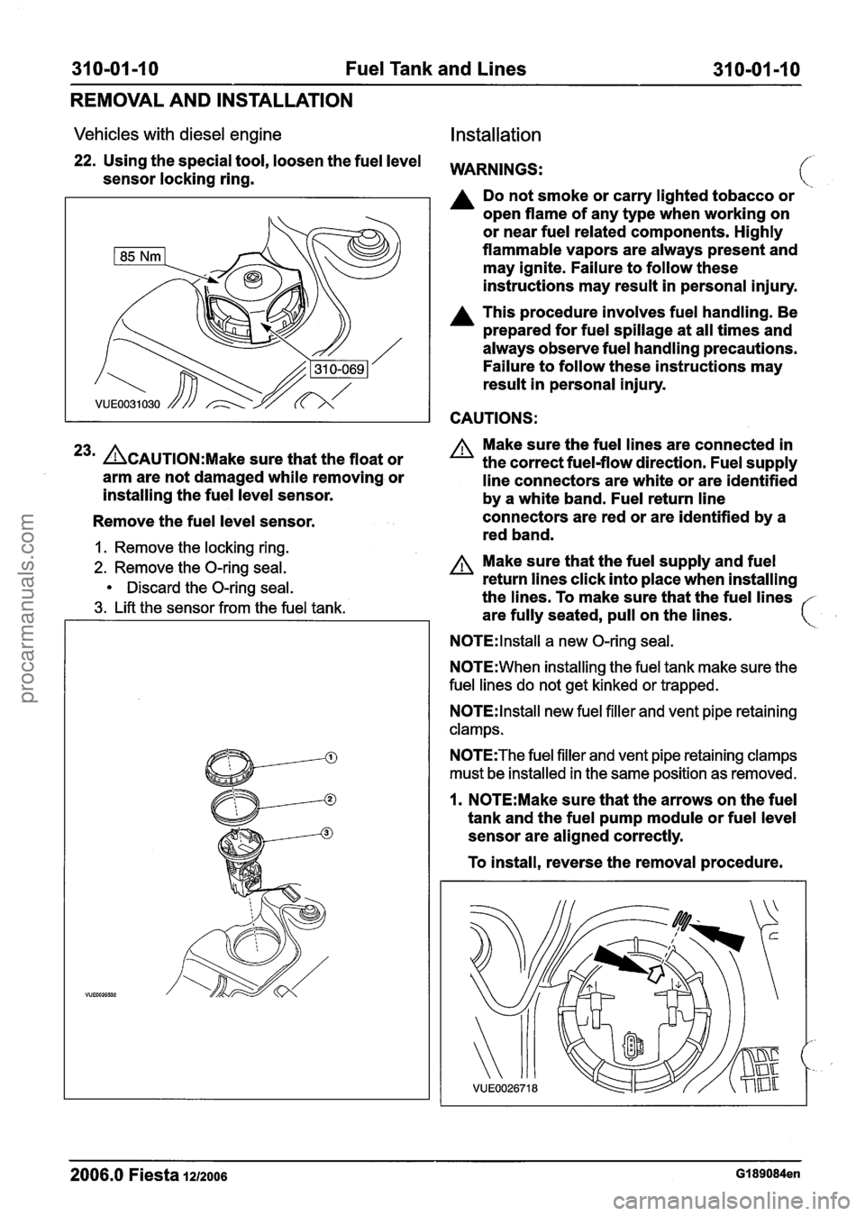
22. Using the special tool, loosen the fuel level WARNINGS: sensor locking ring.
A Do not smoke or carry lighted tobacco or
open flame of any type when working on
or near fuel related components. Highly
flammable vapors are always present and
may ignite. Failure to follow these
instructions may result in personal injury.
A This procedure involves fuel handling. Be
prepared for fuel spillage at all times and
always observe fuel handling precautions.
Failure to follow these instructions may
result in personal injury.
CAUTIONS:
23m &AUTION:M~~~ sure that the float or
arm are not damaged while removing or
installing the fuel level sensor.
Remove the fuel level sensor.
1. Remove the locking ring.
2. Remove the O-ring seal.
Discard the O-ring seal.
3. Lift the sensor from the fuel tank. Make
sure the fuel lines are connected in
the correct fuel-flow direction. Fuel supply
line connectors are white or are identified
by a white band. Fuel return line
connectors are red or are identified by a
red band.
A Make sure that the fuel supply and fuel
return lines click into place when installing
the lines. To make sure that the fuel lines
are fully seated, pull on the lines.
N0TE:lnstall a new O-ring seal.
N0TE:When installing the fuel tank make sure the
fuel lines do not get kinked or trapped.
N0TE:lnstall new fuel filler and vent pipe retaining
clamps.
N0TE:The fuel filler and vent pipe retaining clamps
must be installed in the same position as removed.
1. N0TE:Make sure that the arrows on the fuel
tank and the fuel pump module or fuel level
sensor are aligned correctly.
To install, reverse the removal procedure.
2006.0 Fiesta 1212006 GI 89084en
procarmanuals.com
Page 1213 of 1226

310-01-15 Fuel Tank and Lines 31 0-01 -1 5
REMOVAL AND INSTALLATION
Fuel Level Resistor Card
Removal
All except vehicles with diesel engine Discard the fuel level resistor card
1. Remove the fuel pump and sender unit.
For additional information, refer to: Fuel Tank
(310-01 Fuel Tank and Lines, Removal and
Installation).
Vehicles with diesel engine
2. Remove the fuel level sensor.
For additional information, refer to: Fuel Tank
(310-01 Fuel Tank and Lines, Removal and
Installation).
All vehicles
3. N0TE:Diesel engine variants only have 2 Installation
wires. All vehicles
Disconnect the fuel level resistor card
electrical connectors.
ACAUTION:DO not touch the fuel level
I resistor card surface with tools or hands.
1 i Failure to follow this instruction may result
I in damage to the fuel level resistor card.
4. Using needle nose pliers, remove the fuel
level resistor card.
1. Press the locking tangs.
2. Remove the fuel level resistor card.
N0TE:Make sure that the locking tangs are in the
fully locked position.
N0TE:Make sure that the wiring harness is routed
around the fuel line,
in line with the original
installation.
Install the new fuel level resistor card into
the fuel pump and sender unit or the fuel
level sensor.
2. N0TE:t is not important which electrical
connector is connected to which fuel level
resistor card related pin in the top flange.
N0TE:Diesel engine variants only have 2 wires.
2006.0 Fiesta 1212006 G913201en
procarmanuals.com