2006 TOYOTA RAV4 Engine
[x] Cancel search: EnginePage 1975 of 2000
2AZ-FE ENGINE CONTROL SYSTEM – SFI SYSTEMES–87
ES
DESCRIPTION
Refer to DTC P0136 (see page ES-129).
HINT:
• When any of these DTCs are set, the ECM enters fail-safe mode. The ECM turns off the Heated
Oxygen (HO2) Sensor heater in fail-safe mode. Fail-safe mode continues until the ignition switch is
turned OFF.
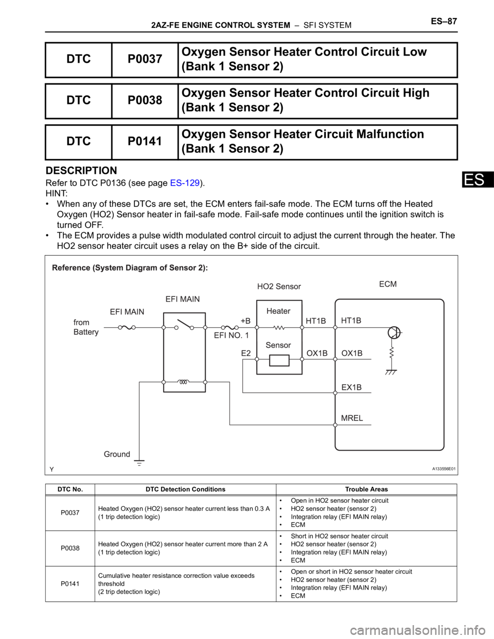
• The ECM provides a pulse width modulated control circuit to adjust the current through the heater. The
HO2 sensor heater circuit uses a relay on the B+ side of the circuit.
DTC P0037Oxygen Sensor Heater Control Circuit Low
(Bank 1 Sensor 2)
DTC P0038Oxygen Sensor Heater Control Circuit High
(Bank 1 Sensor 2)
DTC P0141Oxygen Sensor Heater Circuit Malfunction
(Bank 1 Sensor 2)
DTC No. DTC Detection Conditions Trouble Areas
P0037Heated Oxygen (HO2) sensor heater current less than 0.3 A
(1 trip detection logic)• Open in HO2 sensor heater circuit
• HO2 sensor heater (sensor 2)
• Integration relay (EFI MAIN relay)
•ECM
P0038Heated Oxygen (HO2) sensor heater current more than 2 A
(1 trip detection logic)• Short in HO2 sensor heater circuit
• HO2 sensor heater (sensor 2)
• Integration relay (EFI MAIN relay)
•ECM
P0141Cumulative heater resistance correction value exceeds
threshold
(2 trip detection logic)• Open or short in HO2 sensor heater circuit
• HO2 sensor heater (sensor 2)
• Integration relay (EFI MAIN relay)
•ECM
A133556E01
Page 1976 of 2000
ES–882AZ-FE ENGINE CONTROL SYSTEM – SFI SYSTEM
ES
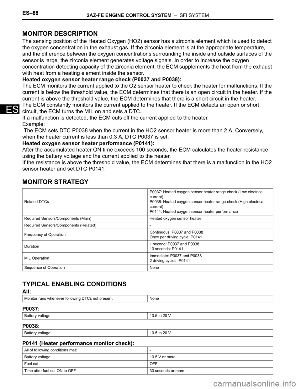
MONITOR DESCRIPTION
The sensing position of the Heated Oxygen (HO2) sensor has a zirconia element which is used to detect
the oxygen concentration in the exhaust gas. If the zirconia element is at the appropriate temperature,
and the difference between the oxygen concentrations surrounding the inside and outside surfaces of the
sensor is large, the zirconia element generates voltage signals. In order to increase the oxygen
concentration detecting capacity of the zirconia element, the ECM supplements the heat from the exhaust
with heat from a heating element inside the sensor.
Heated oxygen sensor heater range check (P0037 and P0038):
The ECM monitors the current applied to the O2 sensor heater to check the heater for malfunctions. If the
current is below the threshold value, the ECM determines that there is an open circuit in the heater. If the
current is above the threshold value, the ECM determines that there is a short circuit in the heater.
The ECM constantly monitors the current applied to the heater. If the ECM detects an open or short
circuit, the ECM turns the MIL on and sets a DTC.
If a malfunction is detected, the ECM cuts off the current applied to the heater.
Example:
The ECM sets DTC P0038 when the current in the HO2 sensor heater is more than 2 A. Conversely,
when the heater current is less than 0.3 A, DTC P0037 is set.
Heated oxygen sensor heater performance (P0141):
After the accumulated heater ON time exceeds 100 seconds, the ECM calculates the heater resistance
using the battery voltage and the current applied to the heater.
If the resistance is above the threshold value, the ECM determines that there is a malfunction in the HO2
sensor heater and set DTC P0141.
MONITOR STRATEGY
TYPICAL ENABLING CONDITIONS
All:
P0037:
P0038:
P0141 (Heater performance monitor check):
Related DTCsP0037: Heated oxygen sensor heater range check (Low electrical
current)
P0038: Heated oxygen sensor heater range check (High electrical
current)
P0141: Heated oxygen sensor heater performance
Required Sensors/Components (Main) Heated oxygen sensor heater
Required Sensors/Components (Related) -
Frequency of OperationContinuous: P0037 and P0038
Once per driving cycle: P0141
Duration1 second: P0037 and P0038
10 seconds: P0141
MIL OperationImmediate: P0037 and P0038
2 driving cycles: P0141
Sequence of Operation None
Monitor runs whenever following DTCs not present None
Battery voltage 10.5 to 20 V
Battery voltage 10.5 to 20 V
All of following conditions met: -
Battery voltage 10.5 V or more
Fuel cut OFF
Time after fuel cut ON to OFF 30 seconds or more
Page 1977 of 2000

2AZ-FE ENGINE CONTROL SYSTEM – SFI SYSTEMES–89
ES
TYPICAL MALFUNCTION THRESHOLDS
P0037:
P0038:
P0141 (Heater performance monitor check):
COMPONENT OPERATING RANGE
WIRING DIAGRAM
Refer to DTC P0136 (see page ES-136).
CONFIRMATION DRIVING PATTERN
These DTCs are detected when the engine idles for 110 seconds or more.
INSPECTION PROCEDURE
HINT:
Sensor 2 refers to the sensor mounted behind the Three-Way Catalytic Converter (TWC) and located far
from the engine assembly.
Read freeze frame data using the intelligent tester. Freeze frame data records the engine condition when
malfunctions are detected. When troubleshooting, freeze frame data can help determine if the vehicle was
moving or stationary, if the engine was warmed up or not, if the air-fuel ratio was lean or rich, and other
data from the time the malfunction occurred.
(a) Disconnect the B19 Heated Oxygen (HO2) sensor
connector.
(b) Measure the resistance of the HO2 sensor connector.
Standard resistance
(c) Reconnect the HO2 sensor connector.
NG
OK
Accumulated heater ON time 100 seconds or more
Heater current Less than 0.3 A
Heater current More than 2 A
Accumulated heater resistance Varies with sensor element temperature (Example: More than 23
)
Heated Oxygen (HO2) sensor heater current0.4 to 1 A (when engine idles, HO2 sensor warmed up and battery
voltage 11 to 14 V)
1INSPECT HEATED OXYGEN SENSOR (HEATER RESISTANCE)
A115661E02
Tester Connections Specified Conditions
1 (HT1B) - 2 (+B) 11 to 16
at 20C (68F)
1 (HT1B) - 4 (E2) 10 k
or higher
REPLACE HEATED OXYGEN SENSOR
Page 1978 of 2000

ES–902AZ-FE ENGINE CONTROL SYSTEM – SFI SYSTEM
ES
(a) Disconnect the B19 HO2 sensor connector.
(b) Turn the ignition switch ON.
(c) Measure the voltage between the terminals of the B19
HO2 sensor connector and body ground.
Standard voltage
(d) Reconnect the HO2 sensor connector.
OK
NG
NG
OK
2CHECK TERMINAL VOLTAGE (+B OF HO2 SENSOR)
A072895E07
Tester Connections Specified Conditions
B19-2 (+B) - Body ground 9 to 14 V
Go to step 5
3INSPECT INTEGRATION RELAY (EFI MAIN RELAY) (See page ES-84)
REPLACE INTEGRATION RELAY
Page 1979 of 2000

2AZ-FE ENGINE CONTROL SYSTEM – SFI SYSTEMES–91
ES
(a) Check the EFI No. 1 fuse.
(b) Disconnect the B19 HO2 sensor connector.
(c) Remove the integration relay from the engine room No. 1
relay block.
(d) Check the resistance.
Standard resistance (Check for open)
Standard resistance (Check for short)
(e) Reconnect the HO2 sensor connector.
(f) Reinstall the integration relay.
NG
OK
4CHECK HARNESS AND CONNECTOR (HO2 SENSOR - EFI RELAY)
A127734E01
Tester Connections Specified Conditions
B19-2 (+B) - 1A-4 (Engine room No. 1
R/B)Below 1
Tester Connections Specified Conditions
B19-2 (+B) or 1A-4 (Engine room No.
1 R/B) - Body ground10 k
or higher
REPAIR OR REPLACE HARNESS OR
CONNECTOR
CHECK ECM POWER SOURCE CIRCUIT
Page 1980 of 2000

ES–922AZ-FE ENGINE CONTROL SYSTEM – SFI SYSTEM
ES
(a) Disconnect the B19 HO2 sensor connector.
(b) Disconnect the B30 ECM connector.
(c) Measure the resistance.
Standard resistance (Check for open)
Standard resistance (Check for short)
(d) Reconnect the HO2 sensor connector.
(e) Reconnect the ECM connector.
NG
OK
(a) Connect the intelligent tester to the DLC3.
(b) Turn the ignition switch ON.
(c) Turn the tester ON.
(d) Clear DTCs (see page ES-35).
(e) Start the engine.
(f) Allow the engine to idle for 2 minutes or more.
(g) Select the following menu items: DIAGNOSIS /
ENHANCED OBD II / DTC INFO / CURRENT CODES.
(h) Read DTCs.
Result
B
A
5CHECK HARNESS AND CONNECTOR (HO2 SENSOR - ECM)
A104950E05
Tester Connections Specified Conditions
B19-1 (HT1B) - B30-47 (HT1B) Below 1
Tester Connections Specified Conditions
B19-1 (HT1B) or B30-47 (HT1B) -
Body ground10 k
or higher
REPAIR OR REPLACE HARNESS OR
CONNECTOR
6CHECK WHETHER DTC OUTPUT RECURS
Display (DTC Output) Proceed To
No output A
P0037, P0038 and/or P0141 B
REPLACE ECM
CHECK FOR INTERMITTENT PROBLEMS
Page 1981 of 2000

2AZ-FE ENGINE CONTROL SYSTEM – SFI SYSTEMES–93
ES
DESCRIPTION
The Mass Air Flow (MAF) meter is a sensor that measures the amount of air flowing through the throttle
valve.
The ECM uses this information to determine the fuel injection time and to provide the appropriate air-fuel
ratio.
Inside the MAF meter, there is a heated platinum wire which is exposed to the flow of intake air.
By applying a specific electrical current to the wire, the ECM heats it to a given temperature. The flow of
incoming air cools both the wire and an internal thermistor, affecting their resistance. To maintain a
constant current value, the ECM varies the voltage applied to these components in the MAF meter. The
voltage level is proportional to the airflow through the sensor, and the ECM uses it to calculate the intake
air volume.
The circuit is constructed so that the platinum hot wire and the temperature sensor create a bridge circuit,
and the power transistor is controlled so that the potentials of A and B remain equal to maintain the
predetermined temperature.
HINT:
When any of these DTCs are set, the ECM enters fail-safe mode. During fail-safe mode, the ignition
timing is calculated by the ECM, according to the engine RPM and throttle valve position. Fail-safe mode
continues until a pass condition is detected.
DTC P0100 Mass or Volume Air Flow Circuit
DTC P0102 Mass or Volume Air Flow Circuit Low Input
DTC P0103 Mass or Volume Air Flow Circuit High Input
DTC No. DTC Detection Conditions Trouble Areas
P0100MAF meter voltage less than 0.2 V, or more than 4.9 V for 3
seconds
(1 trip detection logic)• Open or short in MAF meter circuit
• MAF meter
•ECM
P0102MAF meter voltage less than 0.2 V for 3 seconds
(1 trip detection logic)• Open or short in MAF meter circuit
• MAF meter
•ECM
P0103MAF meter voltage more than 4.9 V for 3 seconds
(1 trip detection logic)• Open or short in MAF meter circuit
• MAF meter
•ECM
A140749E02
Page 1982 of 2000

ES–942AZ-FE ENGINE CONTROL SYSTEM – SFI SYSTEM
ES
HINT:
When any of these DTCs are set, check the air-flow rate by selecting the following menu items on the
intelligent tester: DIAGNOSIS / ENHANCED OBD II/ DATA LIST / PRIMARY / MAF.
MONITOR DESCRIPTION
If there is a defect in the MAF meter or an open or short circuit, the voltage level deviates from the normal
operating range. The ECM interprets this deviation as a malfunction in the MAF meter and sets a DTC.
Example:
When the sensor output voltage remains less than 0.2 V, or more than 4.9 V, for more than 3 seconds, the
ECM sets a DTC.
If the malfunction is not repaired successfully, a DTC is set 3 seconds after the engine is next started.
MONITOR STRATEGY
TYPICAL ENABLING CONDITIONS
TYPICAL MALFUNCTION THRESHOLDS
P0100:
P0102:
P0103:
COMPONENT OPERATING RANGE
Mass Air Flow Rate (g/sec.) Malfunctions
Approximately 0.0• Open in Mass Air Flow (MAF) meter power source circuit
• Open or short in VG circuit
271.0 or more • Open in E2G circuit
Related DTCsP0100: MAF meter range check (Fluctuating)
P0102: MAF meter range check (Low voltage)
P0103: MAF meter range check (High voltage)
Required Sensors/Components (Main) MAF meter
Required Sensors/Components (Related) Crankshaft position sensor
Frequency of Operation Continuous
Duration 3 seconds
MIL OperationImmediate: Engine RPM less than 4,000 rpm
2 driving cycles: Engine RPM 4,000 rpm or more
Sequence of Operation None
Monitor runs whenever following DTCs not present None
MAF meter voltage Less than 0.2 V, or more than 4.9 V
MAF meter voltage Less than 0.2 V
MAF meter voltage More than 4.9 V
MAF meter voltage Between 0.4 V and 2.2 V