Page 131 of 2000

ENGINE - 2GR-FE ENGINEEG-69
Engine Specifications
No. of Cyls. & Arrangement6-cylinder, V Type
Valve Mechanism24-valve DOHC, Chain Drive (with Dual VVT-i)
Combustion ChamberPentroof-type
ManifoldsParallel-flow
Fuel SystemSFI
Ignition SystemDIS
Displacement cm3
(cu. in.)3456 (210.9)
Bore x Stroke mm (in.)94.0 x 83.0 (3.70 x 3.27)
Compression Ratio10.8 : 1
Max. Output (SAE-NET)*1201 kW @ 6200 rpm (269 HP @ 6200 rpm)
Max. Torque (SAE-NET)*1333 N.m @ 4700 rpm (247 ft.lbf @ 4700 rpm)
Intake ValveOpen-3 to 37 BTDC
Valve Timing
Intake ValveClose71 to 31 ABDCVa l v e T i m i n g
Exhaust ValveOpen60 to 25 BBDCExhaust ValveClose4 to 39 ATDC
Firing Order1 - 2 - 3 - 4 - 5 - 6
Octane Rating91 or higher
Engine Oil GradeILSAC multigrade engine oil
CaliforniaULEVII, SFTP
EmissionTailpipeExceptTier2 Bin5 SFTPEmission
Regulation
ppExcept
CaliforniaTier2-Bin5, SFTPg
EvaporativeLEVII, ORVR
Engine Service Mass*2 (Reference) kg (lb)163 (359)
*1: Maximum output and torque rating is determined by revised SAE J1349 standard.
*
2: Weight shows the figure with the oil and engine coolant fully filled.
Page 132 of 2000
ENGINE - 2GR-FE ENGINE
285EG03
: Exhaust Valve Opening Angle Intake VVT-i Operation RangeExhaust VVT-i Operation Range
TDC
374
39
71
31
BDC25
60
Intake VVT-i Operation Range
Exhaust VVT-i Operation Range: Intake Valve Opening Angle
3
EG-70
Valve Timing
Page 189 of 2000
2GR-FE ENGINE CONTROL SYSTEM – SFI SYSTEMES–3
ES
PARTS LOCATION
A136802E02
Page 190 of 2000
ES–42GR-FE ENGINE CONTROL SYSTEM – SFI SYSTEM
ES
A136801E02
Page 191 of 2000
2GR-FE ENGINE CONTROL SYSTEM – SFI SYSTEMES–5
ES
A139337E01
Page 192 of 2000
ES–62GR-FE ENGINE CONTROL SYSTEM – SFI SYSTEM
ES
A127722E03
Page 193 of 2000
ES–4702GR-FE ENGINE CONTROL SYSTEM – ECM
ES
REMOVAL
1. DISCONNECT CABLE FROM NEGATIVE BATTERY
TERMINAL
CAUTION:
Wait at least 90 seconds after disconnecting the
cable from the negative (-) battery terminal to
prevent airbag and seat belt pretensioner activation.
2. REMOVE AIR CLEANER CAP (See page EM-23)
3. REMOVE AIR CLEANER CASE (See page EM-23)
4. REMOVE ECM
(a) Remove the 3 bolts of the ECM bracket.
(b) Disconnect the 2 ECM connectors.
NOTICE:
After disconnecting the connector, make sure
that dirt, water and other foreign matter does not
contact the connecting part of the connector.
(1) Raise the 2 levers while pushing the locks on
the 2 levers, and disconnect the 2 ECM
connectors.
(c) Remove the ECM with bracket.
(d) Remove the 4 screws and 2 ECM brackets.
A124570
A124571E01
A124573
Page 194 of 2000

2GR-FE ENGINE CONTROL SYSTEM – ECMES–471
ES
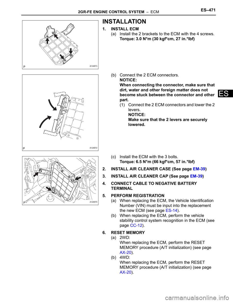
INSTALLATION
1. INSTALL ECM
(a) Install the 2 brackets to the ECM with the 4 screws.
Torque: 3.0 N*m (30 kgf*cm, 27 in.*lbf)
(b) Connect the 2 ECM connectors.
NOTICE:
When connecting the connector, make sure that
dirt, water and other foreign matter does not
become stuck between the connector and other
part.
(1) Connect the 2 ECM connectors and lower the 2
levers.
NOTICE:
Make sure that the 2 levers are securely
lowered.
(c) Install the ECM with the 3 bolts.
Torque: 6.5 N*m (66 kgf*cm, 57 in.*lbf)
2. INSTALL AIR CLEANER CASE (See page EM-39)
3. INSTALL AIR CLEANER CAP (See page EM-39)
4. CONNECT CABLE TO NEGATIVE BATTERY
TERMINAL
5. PERFORM REGISTRATION
(a) When replacing the ECM, the Vehicle Identification
Number (VIN) must be input into the replacement
the new ECM (see page ES-14).
(b) When replacing the ECM, perform the vehicle
stability control system recognition in the ECM (see
page CC-12).
6. RESET MEMORY
(a) 2WD:
When replacing the ECM, perform the RESET
MEMORY procedure (A/T initialization) (see page
AX-20).
(b) 4WD:
When replacing the ECM, perform the RESET
MEMORY procedure (A/T initialization) (see page
AX-20).
A124573
A124572
A124570