Page 204 of 2000

2GR-FE ENGINE MECHANICAL – ENGINE ASSEMBLYEM–29
EM
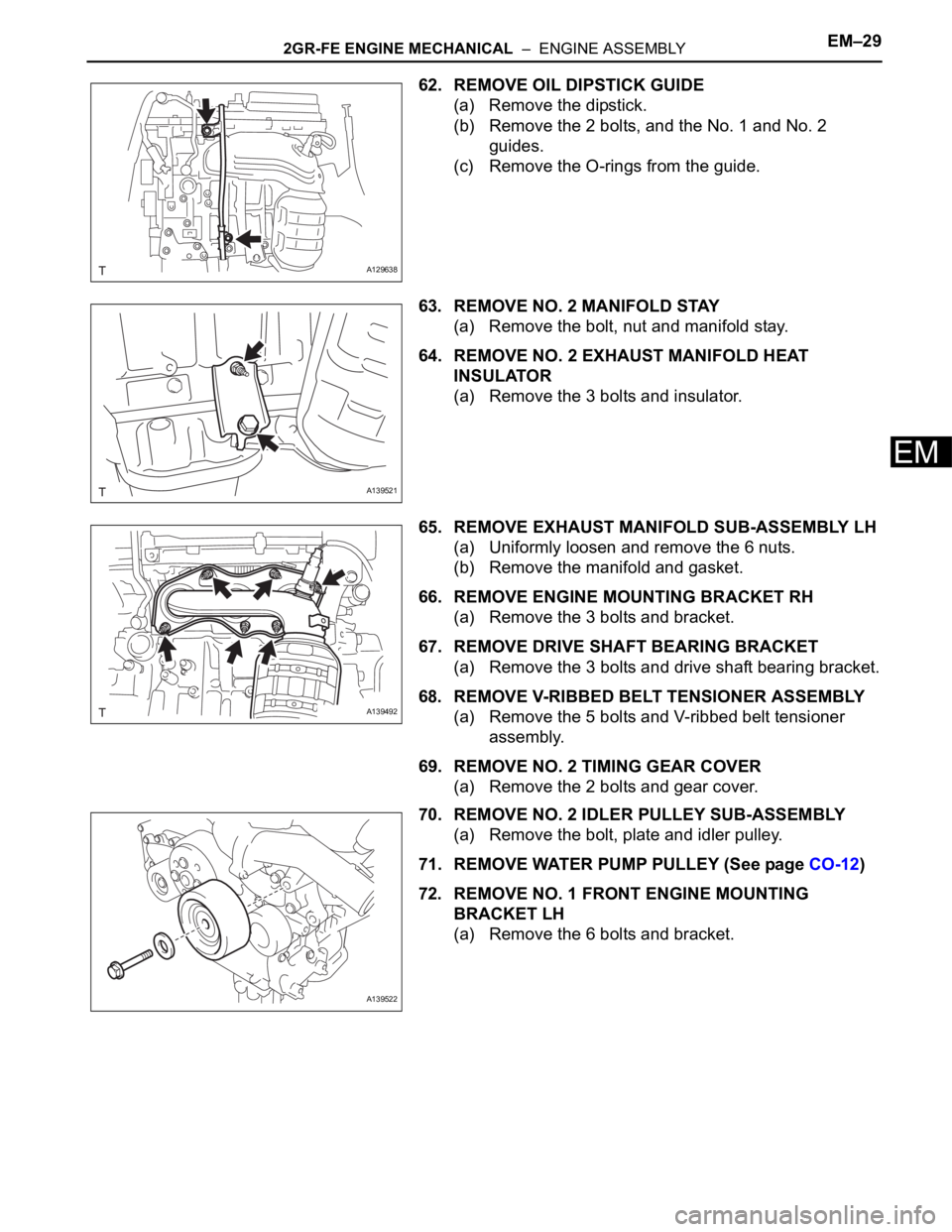
62. REMOVE OIL DIPSTICK GUIDE
(a) Remove the dipstick.
(b) Remove the 2 bolts, and the No. 1 and No. 2
guides.
(c) Remove the O-rings from the guide.
63. REMOVE NO. 2 MANIFOLD STAY
(a) Remove the bolt, nut and manifold stay.
64. REMOVE NO. 2 EXHAUST MANIFOLD HEAT
INSULATOR
(a) Remove the 3 bolts and insulator.
65. REMOVE EXHAUST MANIFOLD SUB-ASSEMBLY LH
(a) Uniformly loosen and remove the 6 nuts.
(b) Remove the manifold and gasket.
66. REMOVE ENGINE MOUNTING BRACKET RH
(a) Remove the 3 bolts and bracket.
67. REMOVE DRIVE SHAFT BEARING BRACKET
(a) Remove the 3 bolts and drive shaft bearing bracket.
68. REMOVE V-RIBBED BELT TENSIONER ASSEMBLY
(a) Remove the 5 bolts and V-ribbed belt tensioner
assembly.
69. REMOVE NO. 2 TIMING GEAR COVER
(a) Remove the 2 bolts and gear cover.
70. REMOVE NO. 2 IDLER PULLEY SUB-ASSEMBLY
(a) Remove the bolt, plate and idler pulley.
71. REMOVE WATER PUMP PULLEY (See page CO-12)
72. REMOVE NO. 1 FRONT ENGINE MOUNTING
BRACKET LH
(a) Remove the 6 bolts and bracket.
A129638
A139521
A139492
A139522
Page 205 of 2000
EM–302GR-FE ENGINE MECHANICAL – ENGINE ASSEMBLY
EM
73. REMOVE ENGINE OIL PRESSURE SWITCH
ASSEMBLY
(a) Using a 24 mm deep socket wrench, remove the
pressure switch.
74. REMOVE KNOCK SENSOR (See page ES-459)
75. REMOVE ENGINE COOLANT TEMPERATURE
SENSOR
(a) Using a 19 mm deep socket wrench, remove the
sensor and gasket.
INSPECTION
1. INSPECT INTAKE MANIFOLD
(a) Using a precision straightedge and feeler gauge,
measure the warpage of the contact surface of the
cylinder head and intake air surge tank.
Maximum warpage
If the warpage is greater than the maximum, replace
the manifold.
2. INSPECT EXHAUST MANIFOLD
(a) Using a precision straightedge and feeler gauge,
measure the surface contacting the cylinder head
for warpage.
Maximum warpage:
0.70 mm (0.0028 in.)
If the warpage is greater than the maximum, replace
the manifold.
A129647
A129648
A137423E01
Item Specified Condition
Intake manifold side 0.8 mm (0.031 in.)
Cylinder head side 0.2 mm (0.008 in.)
A137425
Page 211 of 2000
2GR-FE FUEL – FUEL SYSTEMFU–5
FU
PARTS LOCATION
A136128E01
Page 212 of 2000
FU–62GR-FE FUEL – FUEL SYSTEM
FU
SYSTEM DIAGRAM
1. FUEL FLOW DIAGRAM
A137426E01
Page 213 of 2000
2GR-FE FUEL – FUEL SYSTEMFU–7
FU
2. FUEL SYSTEM WIRING DIAGRAM
A136308E01
Page 214 of 2000
FU–82GR-FE FUEL – FUEL SYSTEM
FU
3. FUEL SYSTEM WIRING DIAGRAM
A136306E01
Page 229 of 2000
2GR-FE EMISSION CONTROL – EMISSION CONTROL SYSTEMEC–3
EC
SYSTEM DIAGRAM
A139300E01
Page 230 of 2000
EC–42GR-FE EMISSION CONTROL – EMISSION CONTROL SYSTEM
EC
A120008E03