2006 TOYOTA RAV4 2gr
[x] Cancel search: 2grPage 1454 of 2000
AXLE – FRONT AXLE HUBAH–13
AH
INSTALLATION
(2006/01- )
HINT:
• Use the same procedures for the RH side and LH side.
• The procedures listed below are the LH side.
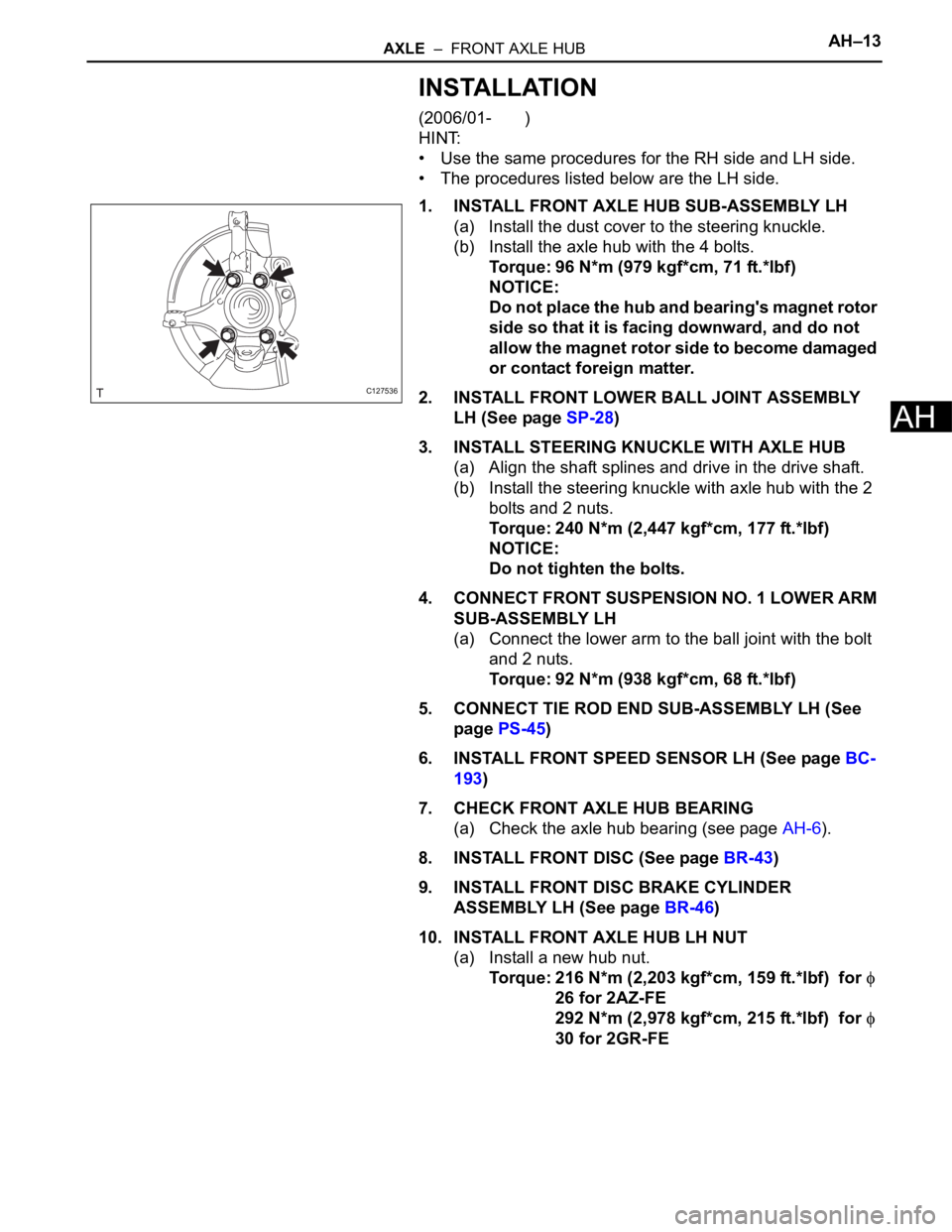
1. INSTALL FRONT AXLE HUB SUB-ASSEMBLY LH
(a) Install the dust cover to the steering knuckle.
(b) Install the axle hub with the 4 bolts.
Torque: 96 N*m (979 kgf*cm, 71 ft.*lbf)
NOTICE:
Do not place the hub and bearing's magnet rotor
side so that it is facing downward, and do not
allow the magnet rotor side to become damaged
or contact foreign matter.
2. INSTALL FRONT LOWER BALL JOINT ASSEMBLY
LH (See page SP-28)
3. INSTALL STEERING KNUCKLE WITH AXLE HUB
(a) Align the shaft splines and drive in the drive shaft.
(b) Install the steering knuckle with axle hub with the 2
bolts and 2 nuts.
Torque: 240 N*m (2,447 kgf*cm, 177 ft.*lbf)
NOTICE:
Do not tighten the bolts.
4. CONNECT FRONT SUSPENSION NO. 1 LOWER ARM
SUB-ASSEMBLY LH
(a) Connect the lower arm to the ball joint with the bolt
and 2 nuts.
Torque: 92 N*m (938 kgf*cm, 68 ft.*lbf)
5. CONNECT TIE ROD END SUB-ASSEMBLY LH (See
page PS-45)
6. INSTALL FRONT SPEED SENSOR LH (See page BC-
193)
7. CHECK FRONT AXLE HUB BEARING
(a) Check the axle hub bearing (see page AH-6).
8. INSTALL FRONT DISC (See page BR-43)
9. INSTALL FRONT DISC BRAKE CYLINDER
ASSEMBLY LH (See page BR-46)
10. INSTALL FRONT AXLE HUB LH NUT
(a) Install a new hub nut.
Torque: 216 N*m (2,203 kgf*cm, 159 ft.*lbf) for
26 for 2AZ-FE
292 N*m (2,978 kgf*cm, 215 ft.*lbf) for
30 for 2GR-FE
C127536
Page 1571 of 2000
BR–16BRAKE – BRAKE PEDAL
BR
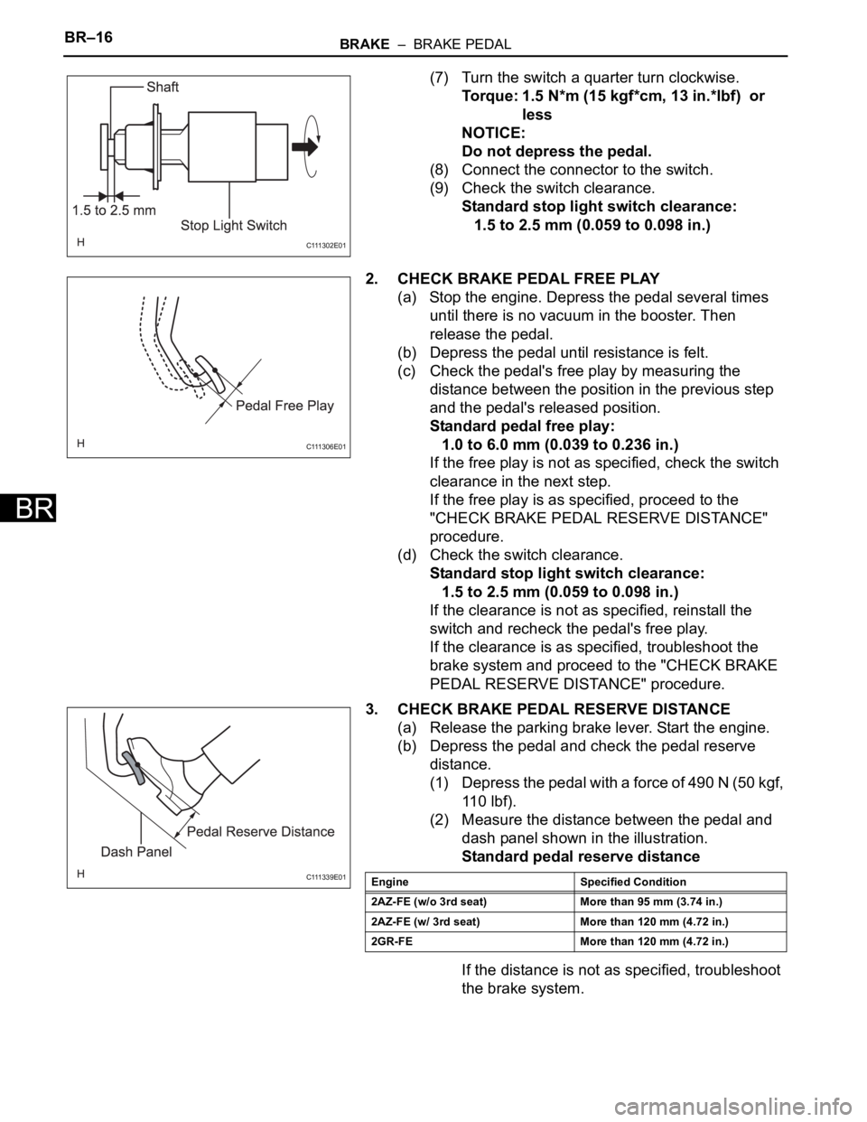
(7) Turn the switch a quarter turn clockwise.
Torque: 1.5 N*m (15 kgf*cm, 13 in.*lbf) or
less
NOTICE:
Do not depress the pedal.
(8) Connect the connector to the switch.
(9) Check the switch clearance.
Standard stop light switch clearance:
1.5 to 2.5 mm (0.059 to 0.098 in.)
2. CHECK BRAKE PEDAL FREE PLAY
(a) Stop the engine. Depress the pedal several times
until there is no vacuum in the booster. Then
release the pedal.
(b) Depress the pedal until resistance is felt.
(c) Check the pedal's free play by measuring the
distance between the position in the previous step
and the pedal's released position.
Standard pedal free play:
1.0 to 6.0 mm (0.039 to 0.236 in.)
If the free play is not as specified, check the switch
clearance in the next step.
If the free play is as specified, proceed to the
"CHECK BRAKE PEDAL RESERVE DISTANCE"
procedure.
(d) Check the switch clearance.
Standard stop light switch clearance:
1.5 to 2.5 mm (0.059 to 0.098 in.)
If the clearance is not as specified, reinstall the
switch and recheck the pedal's free play.
If the clearance is as specified, troubleshoot the
brake system and proceed to the "CHECK BRAKE
PEDAL RESERVE DISTANCE" procedure.
3. CHECK BRAKE PEDAL RESERVE DISTANCE
(a) Release the parking brake lever. Start the engine.
(b) Depress the pedal and check the pedal reserve
distance.
(1) Depress the pedal with a force of 490 N (50 kgf,
11 0 l b f ) .
(2) Measure the distance between the pedal and
dash panel shown in the illustration.
Standard pedal reserve distance
If the distance is not as specified, troubleshoot
the brake system.
C 111 3 0 2 E 0 1
C 111 3 0 6 E 0 1
C 111 3 3 9 E 0 1Engine Specified Condition
2AZ-FE (w/o 3rd seat) More than 95 mm (3.74 in.)
2AZ-FE (w/ 3rd seat) More than 120 mm (4.72 in.)
2GR-FE More than 120 mm (4.72 in.)
Page 1577 of 2000
BR–24BRAKE – BRAKE MASTER CYLINDER
BR
REMOVAL
(2006/01- )
NOTICE:
• The master cylinder and piston are designed so that
the piston can easily fall out. Prevent this by making
sure that the tip of the master cylinder points
downward when handling the master cylinder.
• Make sure foreign matter does not attach to the
master cylinder's piston. If foreign matter attaches,
clean it off with a cloth. Then apply lithium soap base
glycol grease to the entire outer circumference
contact surface area of the piston.
1. REMOVE AIR CLEANER CASE SUB-ASSEMBLY (for
2AZ-FE)
(a) Remove the air cleaner case (see page EM-98).
HINT:
Refer to the procedures from the removal of the
purge VSV up until the removal of the air cleaner
case.
2. REMOVE AIR CLEANER CASE (for 2GR-FE)
(a) Remove the air cleaner case (see page EM-21).
HINT:
Refer to the procedures from the removal of the air
cleaner cap sub-assembly up until the removal of
the air cleaner case.
3. DRAIN BRAKE FLUID
NOTICE:
Wash off brake fluid immediately if it comes in
contact with any painted surface.
4. REMOVE BRAKE MASTER CYLINDER SUB-
ASSEMBLY
(a) Release the vacuum pressure in the brake booster
as follows.
(1) Stop the engine.
(2) Depress the brake pedal several times.
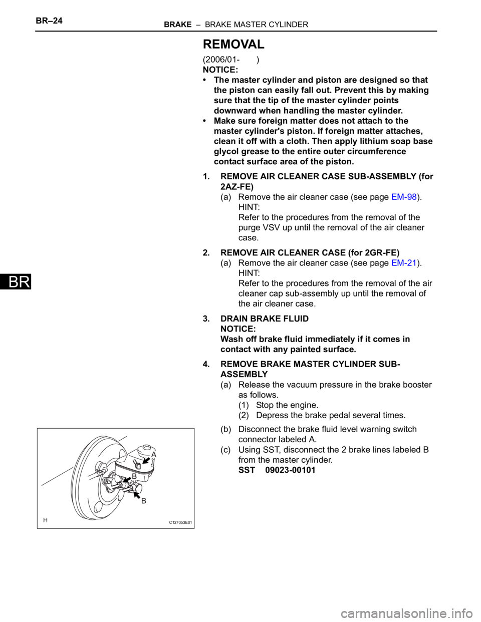
(b) Disconnect the brake fluid level warning switch
connector labeled A.
(c) Using SST, disconnect the 2 brake lines labeled B
from the master cylinder.
SST 09023-00101
C127053E01
Page 1585 of 2000
BR–32BRAKE – BRAKE MASTER CYLINDER
BR
8. INSTALL AIR CLEANER CASE SUB-ASSEMBLY (for
2AZ-FE)
(a) Install the air cleaner case (see page EM-105).
HINT:
Refer to the procedures from the installation of the
air cleaner case up until the installation of the purge
VSV.
9. INSTALL AIR CLEANER CASE (for 2GR-FE)
(a) Install the air cleaner case (see page EM-31).
HINT:
Refer to the procedures from the installation of the
air cleaner case up until the installation of the air
cleaner cap sub-assembly.
Page 1587 of 2000
BR–32BRAKE – BRAKE BOOSTER
BR
REMOVAL
(2006/01- )
1. REMOVE AIR CLEANER CASE SUB-ASSEMBLY (for
2AZ-FE)
(a) Remove the air cleaner case (see page EM-98).
HINT:
Refer to the procedures from the removal of the
purge VSV up until the removal of the air cleaner
case.
2. REMOVE AIR CLEANER CASE (for 2GR-FE)
(a) Remove the air cleaner case (see page EM-21).
HINT:
Refer to the procedures from the removal of the air
cleaner cap sub-assembly up until the removal of
the air cleaner case.
3. DRAIN BRAKE FLUID
NOTICE:
Wash off brake fluid immediately if it comes in
contact with any painted surface.
4. DISCONNECT BRAKE LINES (See page BC-183)
5. REMOVE ABS AND TRACTION ACTUATOR
ASSEMBLY WITH BRACKET (See page BC-184)
6. REMOVE BRAKE MASTER CYLINDER SUB-
ASSEMBLY (See page BR-22)
7. DISCONNECT VACUUM HOSE
8. REMOVE PUSH ROD PIN
(a) Remove the clip from the push rod pin.
(b) Remove the push rod pin from the push rod clevis.
9. REMOVE BRAKE MASTER CYLINDER PUSH ROD
CLEVIS
(a) Loosen the push rod clevis lock nut.
(b) Remove the push rod clevis.
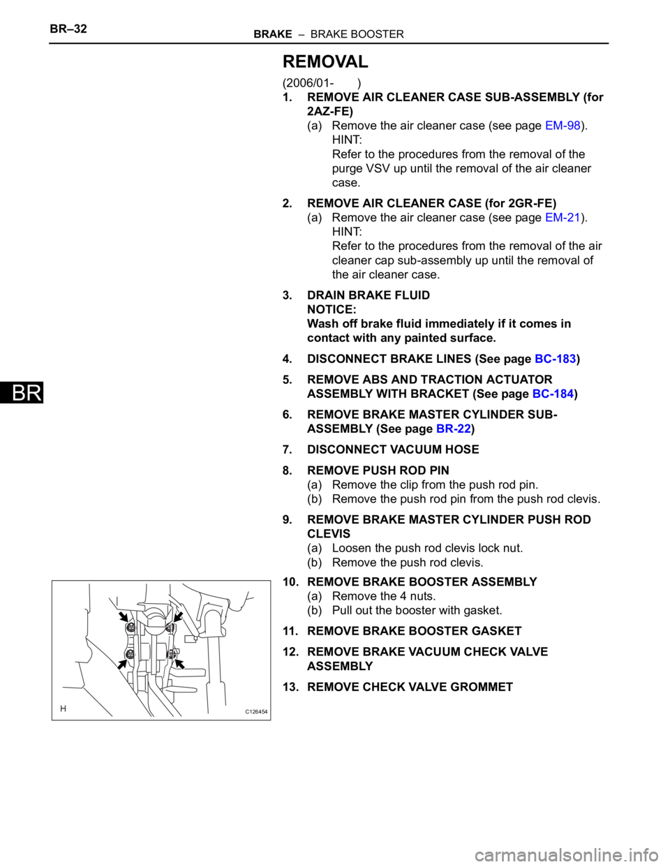
10. REMOVE BRAKE BOOSTER ASSEMBLY
(a) Remove the 4 nuts.
(b) Pull out the booster with gasket.
11. REMOVE BRAKE BOOSTER GASKET
12. REMOVE BRAKE VACUUM CHECK VALVE
ASSEMBLY
13. REMOVE CHECK VALVE GROMMET
C126454
Page 1652 of 2000
AC–24AIR CONDITIONING – AIR CONDITIONING SYSTEM (for Automatic Air Conditioning Sys-
tem)
AC
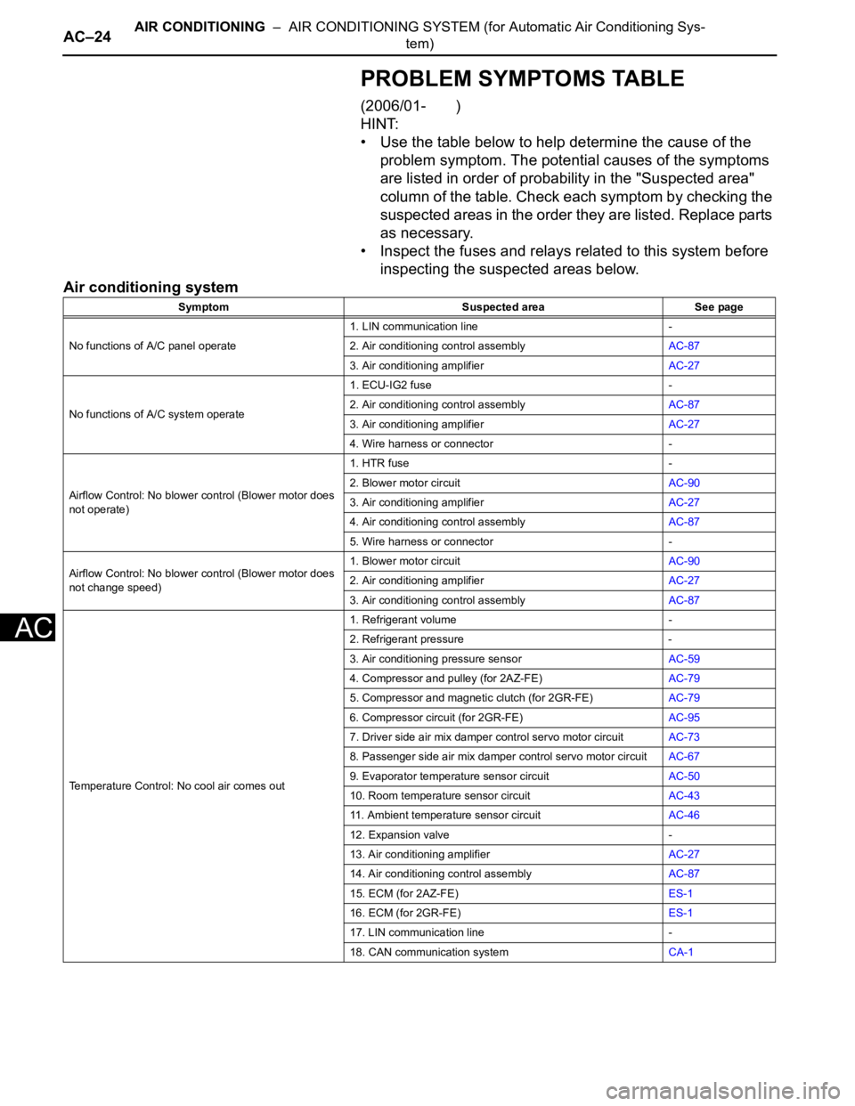
PROBLEM SYMPTOMS TABLE
(2006/01- )
HINT:
• Use the table below to help determine the cause of the
problem symptom. The potential causes of the symptoms
are listed in order of probability in the "Suspected area"
column of the table. Check each symptom by checking the
suspected areas in the order they are listed. Replace parts
as necessary.
• Inspect the fuses and relays related to this system before
inspecting the suspected areas below.
Air conditioning system
Symptom Suspected area See page
No functions of A/C panel operate1. LIN communication line -
2. Air conditioning control assemblyAC-87
3. Air conditioning amplifierAC-27
No functions of A/C system operate1. ECU-IG2 fuse -
2. Air conditioning control assemblyAC-87
3. Air conditioning amplifierAC-27
4. Wire harness or connector -
Airflow Control: No blower control (Blower motor does
not operate)1. HTR fuse -
2. Blower motor circuitAC-90
3. Air conditioning amplifierAC-27
4. Air conditioning control assemblyAC-87
5. Wire harness or connector -
Airflow Control: No blower control (Blower motor does
not change speed)1. Blower motor circuitAC-90
2. Air conditioning amplifierAC-27
3. Air conditioning control assemblyAC-87
Temperature Control: No cool air comes out1. Refrigerant volume -
2. Refrigerant pressure -
3. Air conditioning pressure sensorAC-59
4. Compressor and pulley (for 2AZ-FE)AC-79
5. Compressor and magnetic clutch (for 2GR-FE)AC-79
6. Compressor circuit (for 2GR-FE)AC-95
7. Driver side air mix damper control servo motor circuitAC-73
8. Passenger side air mix damper control servo motor circuitAC-67
9. Evaporator temperature sensor circuitAC-50
10. Room temperature sensor circuitAC-43
11. Ambient temperature sensor circuitAC-46
12. Expansion valve -
13. Air conditioning amplifierAC-27
14. Air conditioning control assemblyAC-87
15. ECM (for 2AZ-FE)ES-1
16. ECM (for 2GR-FE)ES-1
17. LIN communication line -
18. CAN communication systemCA-1
Page 1653 of 2000
AIR CONDITIONING – AIR CONDITIONING SYSTEM (for Automatic Air Conditioning Sys-
tem)AC–25
AC
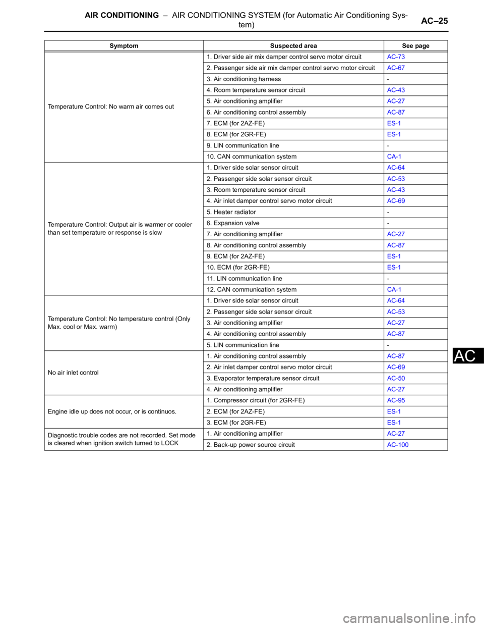
Temperature Control: No warm air comes out1. Driver side air mix damper control servo motor circuitAC-73
2. Passenger side air mix damper control servo motor circuitAC-67
3. Air conditioning harness -
4. Room temperature sensor circuitAC-43
5. Air conditioning amplifierAC-27
6. Air conditioning control assemblyAC-87
7. ECM (for 2AZ-FE)ES-1
8. ECM (for 2GR-FE)ES-1
9. LIN communication line -
10. CAN communication systemCA-1
Temperature Control: Output air is warmer or cooler
than set temperature or response is slow1. Driver side solar sensor circuitAC-64
2. Passenger side solar sensor circuitAC-53
3. Room temperature sensor circuitAC-43
4. Air inlet damper control servo motor circuitAC-69
5. Heater radiator -
6. Expansion valve -
7. Air conditioning amplifierAC-27
8. Air conditioning control assemblyAC-87
9. ECM (for 2AZ-FE)ES-1
10. ECM (for 2GR-FE)ES-1
11. LIN communication line -
12. CAN communication systemCA-1
Temperature Control: No temperature control (Only
Max. cool or Max. warm)1. Driver side solar sensor circuitAC-64
2. Passenger side solar sensor circuitAC-53
3. Air conditioning amplifierAC-27
4. Air conditioning control assemblyAC-87
5. LIN communication line -
No air inlet control1. Air conditioning control assemblyAC-87
2. Air inlet damper control servo motor circuitAC-69
3. Evaporator temperature sensor circuitAC-50
4. Air conditioning amplifierAC-27
Engine idle up does not occur, or is continuos.1. Compressor circuit (for 2GR-FE)AC-95
2. ECM (for 2AZ-FE)ES-1
3. ECM (for 2GR-FE)ES-1
Diagnostic trouble codes are not recorded. Set mode
is cleared when ignition switch turned to LOCK1. Air conditioning amplifierAC-27
2. Back-up power source circuitAC-100 Symptom Suspected area See page
Page 1658 of 2000
AC–30AIR CONDITIONING – AIR CONDITIONING SYSTEM (for Automatic Air Conditioning Sys-
tem)
AC
HINT:
*: for 2GR-FE
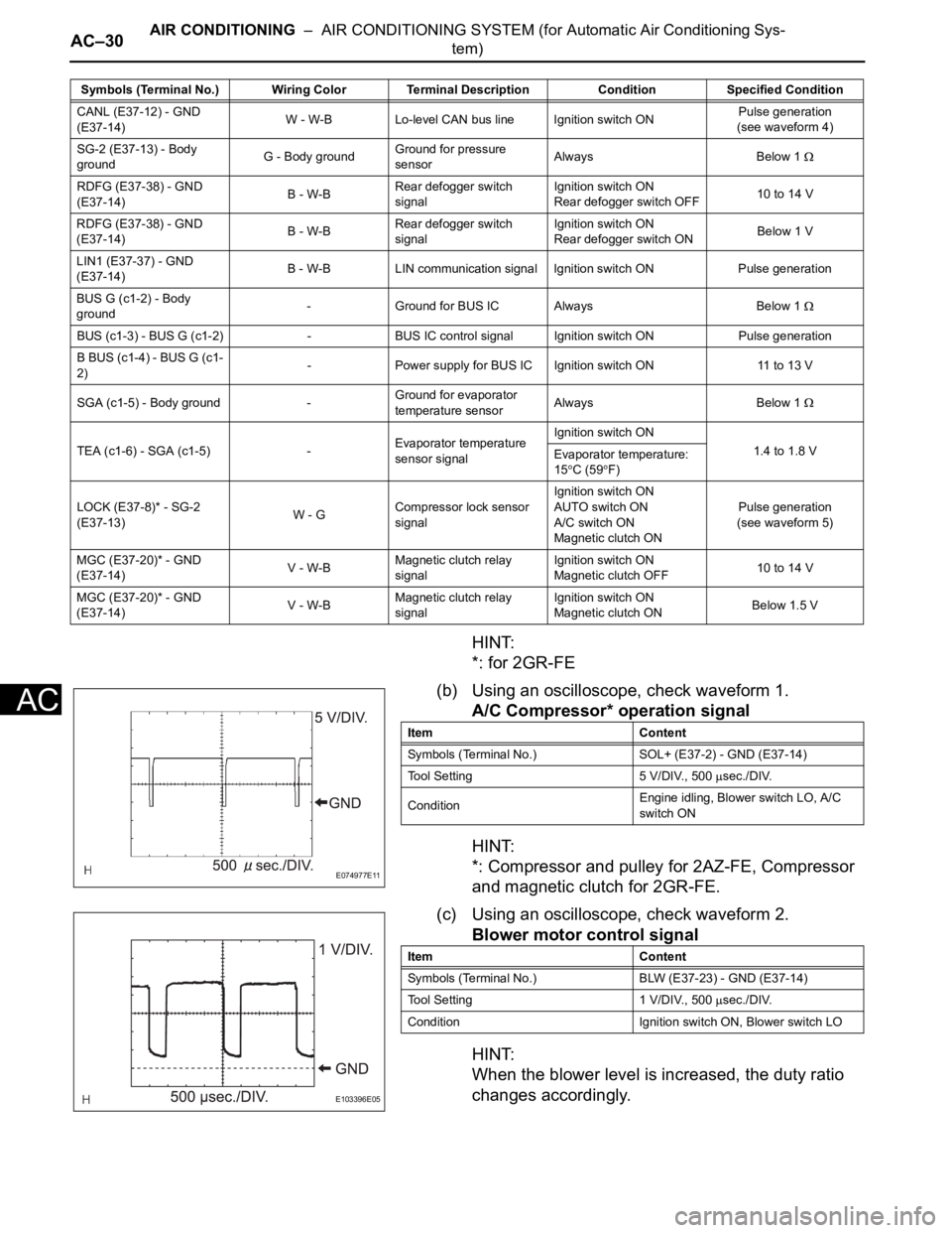
(b) Using an oscilloscope, check waveform 1.
A/C Compressor* operation signal
HINT:
*: Compressor and pulley for 2AZ-FE, Compressor
and magnetic clutch for 2GR-FE.
(c) Using an oscilloscope, check waveform 2.
Blower motor control signal
HINT:
When the blower level is increased, the duty ratio
changes accordingly.
CANL (E37-12) - GND
(E37-14)W - W-B Lo-level CAN bus line Ignition switch ONPulse generation
(see waveform 4)
SG-2 (E37-13) - Body
groundG - Body groundGround for pressure
sensorAlways Below 1
RDFG (E37-38) - GND
(E37-14)B - W-BRear defogger switch
signalIgnition switch ON
Rear defogger switch OFF10 to 14 V
RDFG (E37-38) - GND
(E37-14)B - W-BRear defogger switch
signalIgnition switch ON
Rear defogger switch ONBelow 1 V
LIN1 (E37-37) - GND
(E37-14)B - W-B LIN communication signal Ignition switch ON Pulse generation
BUS G (c1-2) - Body
ground- Ground for BUS IC Always Below 1
BUS (c1-3) - BUS G (c1-2) - BUS IC control signal Ignition switch ON Pulse generation
B BUS (c1-4) - BUS G (c1-
2)- Power supply for BUS IC Ignition switch ON 11 to 13 V
SGA (c1-5) - Body ground -Ground for evaporator
temperature sensorAlways Below 1
TEA (c1-6) - SGA (c1-5) -Evaporator temperature
sensor signalIgnition switch ON
1.4 to 1.8 V
Evaporator temperature:
15
C (59F)
LOCK (E37-8)* - SG-2
(E37-13)W - GCompressor lock sensor
signalIgnition switch ON
AUTO switch ON
A/C switch ON
Magnetic clutch ONPulse generation
(see waveform 5)
MGC (E37-20)* - GND
(E37-14)V - W-BMagnetic clutch relay
signalIgnition switch ON
Magnetic clutch OFF10 to 14 V
MGC (E37-20)* - GND
(E37-14)V - W-BMagnetic clutch relay
signalIgnition switch ON
Magnetic clutch ONBelow 1.5 V Symbols (Terminal No.) Wiring Color Terminal Description ConditionSpecified Condition
E074977E11
Item Content
Symbols (Terminal No.) SOL+ (E37-2) - GND (E37-14)
Tool Setting 5 V/DIV., 500
sec./DIV.
ConditionEngine idling, Blower switch LO, A/C
switch ON
E103396E05
Item Content
Symbols (Terminal No.) BLW (E37-23) - GND (E37-14)
Tool Setting 1 V/DIV., 500
sec./DIV.
Condition Ignition switch ON, Blower switch LO