Page 929 of 2000

CH–62GR-FE CHARGING – CHARGING SYSTEM
CH
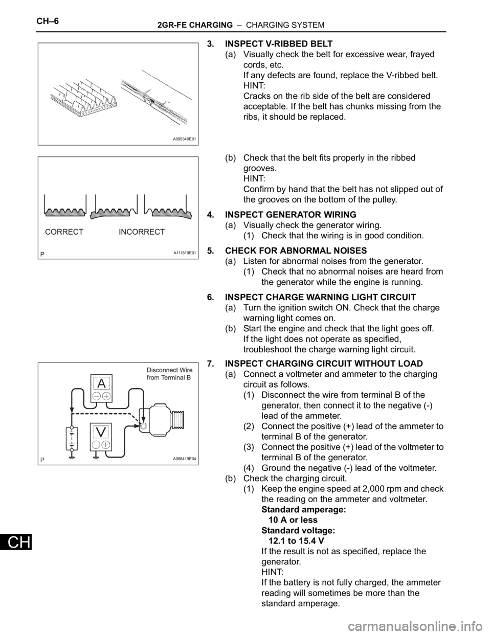
3. INSPECT V-RIBBED BELT
(a) Visually check the belt for excessive wear, frayed
cords, etc.
If any defects are found, replace the V-ribbed belt.
HINT:
Cracks on the rib side of the belt are considered
acceptable. If the belt has chunks missing from the
ribs, it should be replaced.
(b) Check that the belt fits properly in the ribbed
grooves.
HINT:
Confirm by hand that the belt has not slipped out of
the grooves on the bottom of the pulley.
4. INSPECT GENERATOR WIRING
(a) Visually check the generator wiring.
(1) Check that the wiring is in good condition.
5. CHECK FOR ABNORMAL NOISES
(a) Listen for abnormal noises from the generator.
(1) Check that no abnormal noises are heard from
the generator while the engine is running.
6. INSPECT CHARGE WARNING LIGHT CIRCUIT
(a) Turn the ignition switch ON. Check that the charge
warning light comes on.
(b) Start the engine and check that the light goes off.
If the light does not operate as specified,
troubleshoot the charge warning light circuit.
7. INSPECT CHARGING CIRCUIT WITHOUT LOAD
(a) Connect a voltmeter and ammeter to the charging
circuit as follows.
(1) Disconnect the wire from terminal B of the
generator, then connect it to the negative (-)
lead of the ammeter.
(2) Connect the positive (+) lead of the ammeter to
terminal B of the generator.
(3) Connect the positive (+) lead of the voltmeter to
terminal B of the generator.
(4) Ground the negative (-) lead of the voltmeter.
(b) Check the charging circuit.
(1) Keep the engine speed at 2,000 rpm and check
the reading on the ammeter and voltmeter.
Standard amperage:
10 A or less
Standard voltage:
12.1 to 15.4 V
If the result is not as specified, replace the
generator.
HINT:
If the battery is not fully charged, the ammeter
reading will sometimes be more than the
standard amperage.
A095340E01
A111819E01
A088419E04
Page 930 of 2000
2GR-FE CHARGING – CHARGING SYSTEMCH–7
CH
8. INSPECT CHARGING CIRCUIT WITH LOAD
(a) With the engine running at 2,000 rpm, turn the high
beam headlights ON and turn the heater blower
switch to the "HI" position.
(b) Check the reading on the ammeter.
Standard amperage:
30 A or more
If the ammeter reading is less than the standard
amperage, repair the generator.
HINT:
If the battery is fully charged, the indication will
sometimes be less than the standard amperage.
If this is the case, add more electrical load (operate
the wipers, rear window defogger, etc.) and check
the reading on the ammeter again.
Page 931 of 2000
CH–122GR-FE CHARGING – GENERATOR
CH
REMOVAL
1. REMOVE RADIATOR ASSEMBLY
(a) Remove the radiator (see page CO-36).
2. REMOVE FRONT WHEEL RH
3. REMOVE ENGINE UNDER COVER REAR RH (See
page EM-21)
4. REMOVE FRONT SUSPENSION MEMBER
REINFORCEMENT RH (See page EM-7)
5. REMOVE RADIATOR RESERVOIR TANK (See page
CO-19)
6. REMOVE FAN AND GENERATOR V BELT (See page
EM-8)
7. REMOVE GENERATOR ASSEMBLY
(a) Disconnect the 2 wire harness clamps.
(b) Remove the terminal cap.
(c) Remove the nut and disconnect the generator wire
from terminal B.
(d) Disconnect the generator connector from the
generator.
(e) Remove the bolt from the cylinder block.
A132430
A132431
A132432E01
Page 932 of 2000
2GR-FE CHARGING – GENERATORCH–13
CH
(f) Remove the 2 bolts and generator.
DISASSEMBLY
1. REMOVE GENERATOR PULLEY WITH CLUTCH
(a) Using a screwdriver, puncture the center of the cap
and pry it off the pulley.
NOTICE:
Do not reuse the cap.
(b) Install SST to the pulley as shown in the illustration.
SST 09820-63020
(c) Mount SST (A) in a vise.
(d) Turn SST (B) clockwise to loosen the pulley.
(e) Remove the pulley.
2. REMOVE GENERATOR BRUSH HOLDER ASSEMBLY
(a) Remove the bolt and wire harness clamp stay.
A132433
A136851
A136849E01
A136852E01
A132434
Page 933 of 2000
CH–142GR-FE CHARGING – GENERATOR
CH
(b) Remove the bolt and bracket.
(c) Remove the 3 nuts and generator rear end cover.
(d) Remove the terminal insulator.
(e) Remove the 2 screws and generator brush holder.
3. REMOVE GENERATOR ROTOR ASSEMBLY
(a) Remove the 4 bolts.
A132435
A136839
A136840
A136841
A136842
Page 934 of 2000

2GR-FE CHARGING – GENERATORCH–15
CH
(b) Using SST, remove the generator rectifier end
frame.
SST 09950-40011 (09951-04020, 09952-04010,
09953-04020, 09954-04010, 09955-04071,
09957-04010, 09958-04011)
(c) Remove the washer.
(d) Remove the generator rotor.
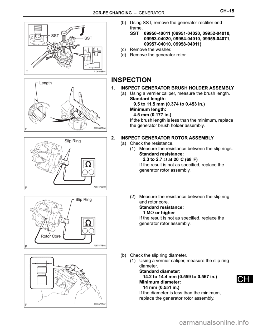
INSPECTION
1. INSPECT GENERATOR BRUSH HOLDER ASSEMBLY
(a) Using a vernier caliper, measure the brush length.
Standard length:
9.5 to 11.5 mm (0.374 to 0.453 in.)
Minimum length:
4.5 mm (0.177 in.)
If the brush length is less than the minimum, replace
the generator brush holder assembly.
2. INSPECT GENERATOR ROTOR ASSEMBLY
(a) Check the resistance.
(1) Measure the resistance between the slip rings.
Standard resistance:
2.3 to 2.7
at 20C (68F)
If the result is not as specified, replace the
generator rotor assembly.
(2) Measure the resistance between the slip ring
and rotor core.
Standard resistance:
1 M
or higher
If the result is not as specified, replace the
generator rotor assembly.
(b) Check the slip ring diameter.
(1) Using a vernier caliper, measure the slip ring
diameter.
Standard diameter:
14.2 to 14.4 mm (0.559 to 0.567 in.)
Minimum diameter:
14 mm (0.551 in.)
If the diameter is less than the minimum,
replace the generator rotor assembly.
A136843E01
A079305E04
A097476E02
A097477E02
A097470E02
Page 935 of 2000
CH–162GR-FE CHARGING – GENERATOR
CH
(c) Check the appearance.
(1) Check that the bearing is not rough or worn.
OK:
The bearing rotates smoothly.
If the result is not as specified, replace the
generator rotor assembly.
3. INSPECT GENERATOR DRIVE END FRAME
BEARING
(a) Check that the bearing is not rough or worn.
OK:
The bearing rotates smoothly.
If the bearing does not rotate smoothly, replace the
bearing.
4. INSPECT GENERATOR PULLEY WITH CLUTCH
(a) Hold the center of the pulley, and confirm that the
outer ring turns counterclockwise and does not turn
clockwise.
If the result is not as specified, replace the
generator pulley with clutch.
REPLACEMENT
1. REPLACE GENERATOR DRIVE END FRAME
BEARING
(a) Remove the 4 screws and bearing retainer.
(b) Using SST and a hammer, tap out the bearing.
SST 09950-60010 (09951-00250), 09950-70010
(09951-07100)
A097469E01
A136846
A126783E02
A136844
A136845E01
Page 936 of 2000
2GR-FE CHARGING – GENERATORCH–17
CH
(c) Using SST and a press, press in a new bearing.
SST 09950-60010 (09951-00250), 09950-70010
(09951-07100)
(d) Install the bearing retainer with the 4 screws.
Torque: 2.3 N*m (23 kgf*cm, 20 in.*lbf)
REASSEMBLY
1. INSTALL GENERATOR ROTOR ASSEMBLY
(a) Install the washer onto the generator rectifier end
frame.
(b) Install the generator rotor onto the generator
rectifier end frame.
(c) Using a 21 mm deep socket wrench and press,
slowly push the generator drive end frame onto the
generator rectifier frame.
A136847E01
A136844
A097468E01
A097467E01
A136848E01