Page 876 of 2000

LU–162GR-FE LUBRICATION – OIL PUMP
LU
INSPECTION
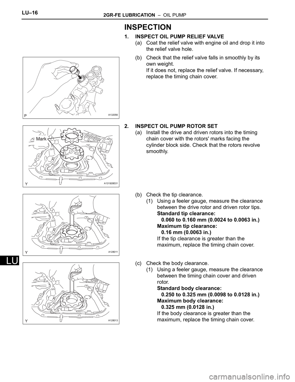
1. INSPECT OIL PUMP RELIEF VALVE
(a) Coat the relief valve with engine oil and drop it into
the relief valve hole.
(b) Check that the relief valve falls in smoothly by its
own weight.
If it does not, replace the relief valve. If necessary,
replace the timing chain cover.
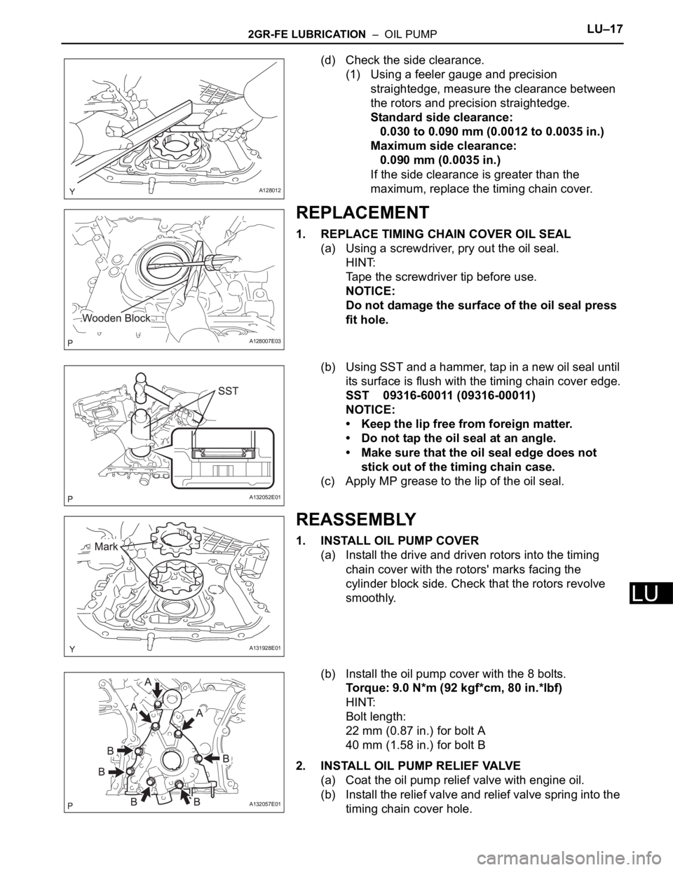
2. INSPECT OIL PUMP ROTOR SET
(a) Install the drive and driven rotors into the timing
chain cover with the rotors' marks facing the
cylinder block side. Check that the rotors revolve
smoothly.
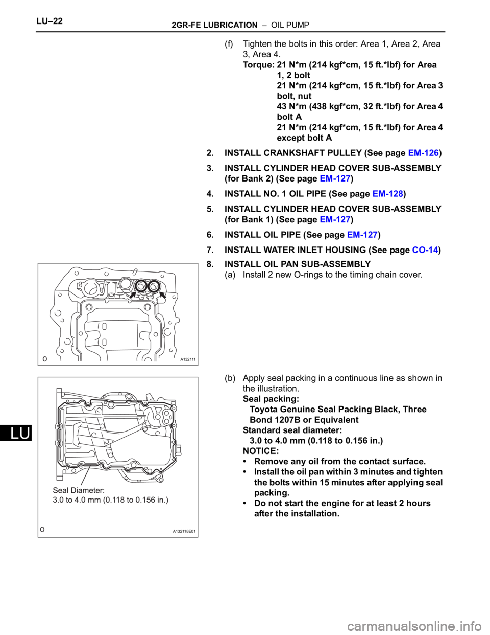
(b) Check the tip clearance.
(1) Using a feeler gauge, measure the clearance
between the drive rotor and driven rotor tips.
Standard tip clearance:
0.060 to 0.160 mm (0.0024 to 0.0063 in.)
Maximum tip clearance:
0.16 mm (0.0063 in.)
If the tip clearance is greater than the
maximum, replace the timing chain cover.
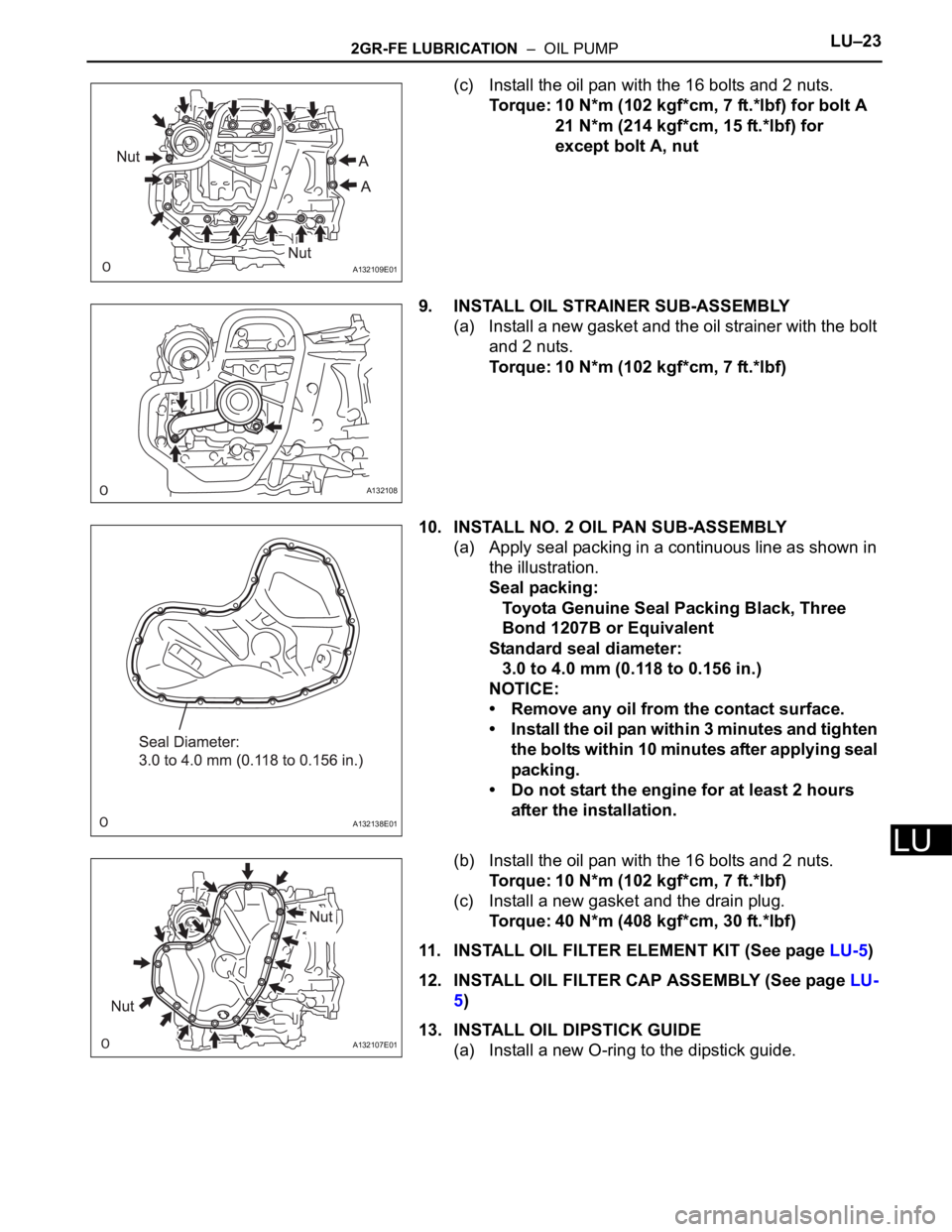
(c) Check the body clearance.
(1) Using a feeler gauge, measure the clearance
between the timing chain cover and driven
rotor.
Standard body clearance:
0.250 to 0.325 mm (0.0098 to 0.0128 in.)
Maximum body clearance:
0.325 mm (0.0128 in.)
If the body clearance is greater than the
maximum, replace the timing chain cover.
A132056
A131928E01
A128011
A128013
Page 877 of 2000

2GR-FE LUBRICATION – OIL PUMPLU–17
LU
(d) Check the side clearance.
(1) Using a feeler gauge and precision
straightedge, measure the clearance between
the rotors and precision straightedge.
Standard side clearance:
0.030 to 0.090 mm (0.0012 to 0.0035 in.)
Maximum side clearance:
0.090 mm (0.0035 in.)
If the side clearance is greater than the
maximum, replace the timing chain cover.
REPLACEMENT
1. REPLACE TIMING CHAIN COVER OIL SEAL
(a) Using a screwdriver, pry out the oil seal.
HINT:
Tape the screwdriver tip before use.
NOTICE:
Do not damage the surface of the oil seal press
fit hole.
(b) Using SST and a hammer, tap in a new oil seal until
its surface is flush with the timing chain cover edge.
SST 09316-60011 (09316-00011)
NOTICE:
• Keep the lip free from foreign matter.
• Do not tap the oil seal at an angle.
• Make sure that the oil seal edge does not
stick out of the timing chain case.
(c) Apply MP grease to the lip of the oil seal.
REASSEMBLY
1. INSTALL OIL PUMP COVER
(a) Install the drive and driven rotors into the timing
chain cover with the rotors' marks facing the
cylinder block side. Check that the rotors revolve
smoothly.
(b) Install the oil pump cover with the 8 bolts.
Torque: 9.0 N*m (92 kgf*cm, 80 in.*lbf)
HINT:
Bolt length:
22 mm (0.87 in.) for bolt A
40 mm (1.58 in.) for bolt B
2. INSTALL OIL PUMP RELIEF VALVE
(a) Coat the oil pump relief valve with engine oil.
(b) Install the relief valve and relief valve spring into the
timing chain cover hole.
A128012
A128007E03
A132052E01
A131928E01
A132057E01
Page 878 of 2000
LU–182GR-FE LUBRICATION – OIL PUMP
LU
(c) Using a 27 mm socket wrench, install the plug.
Torque: 49 N*m (500 kgf*cm, 36 ft.*lbf)
INSTALLATION
1. INSTALL TIMING CHAIN COVER SUB-ASSEMBLY (w/
Oil Pump)
(a) Install a new gasket.
(b) Align the oil pump's drive rotor spline and the
crankshaft as shown in the illustration.
A132097
A132104
A132105E01
Page 879 of 2000
2GR-FE LUBRICATION – OIL PUMPLU–19
LU
(c) Apply seal packing in a continuous bead to the
engine unit as shown in the illustration.
Seal packing:
Toyota Genuine Seal Packing Block, Three
Bond 1207B or Equivalent.
Standard seal diameter:
3.0 mm (0.118 in.) or more
Standard length:
10 mm (0.394 in.)
NOTICE:
• Be sure to clean and degrease the contact
surfaces, especially the hatched areas in the
illustration.
• When the contact surfaces are wet, wipe them
off with an oil-free cloth before applying seal
packing.
• Install the timing chin cover within 3 minutes
and tighten the bolts within 15 minutes after
applying seal packing.
• Do not start the engine for at least 2 hours
after the installation.
A132102E01
Page 880 of 2000
LU–202GR-FE LUBRICATION – OIL PUMP
LU
(d) Apply seal packing in a continuous line to the timing
chain cover as shown in the illustration.
Seal packing:
For oil related part:
Toyota Genuine Seal Packing Black, Three
Bond 1207B or Equivalent
For water related part:
Toyota Genuine Seal Packing 1282B, Three
Bond 1282B or Equivalent
A132178E01
Page 881 of 2000
2GR-FE LUBRICATION – OIL PUMPLU–21
LU
Standard seal diameter
NOTICE:
• When the contact surfaces are wet, wipe them
off with an oil-free cloth before applying seal
packing.
• Install the timing chain cover within 3 minutes
and tighten the bolts within 15 minutes after
applying seal packing.
• Do not start the engine for at least 2 hours
after the installation.
(e) Temporarily install the timing chain cover with the 23
bolts and 2 nuts.
NOTICE:
Make sure there is no oil on the bolts. If there is
oil on the bolts, clean them before installing
them.
HINT:
Bolt length:
40 mm (1.57 in.) for bolt A
55 mm (2.17 in.) for bolt B
25 mm (0.98 in.) for bolt C
Position Specified Condition
A - A 6.0 mm (0.236 in.)
B - B 6.5 mm (0.256 in.)
Continuous line area 4.5 mm (0.138 in.) or more
Dashed line area 3.5 mm (0.138 in.) or more
Alternate long and short dashed line
area3.5 mm (0.138 in.) or more
A132106E01
Page 882 of 2000

LU–222GR-FE LUBRICATION – OIL PUMP
LU
(f) Tighten the bolts in this order: Area 1, Area 2, Area
3, Area 4.
Torque: 21 N*m (214 kgf*cm, 15 ft.*lbf) for Area
1, 2 bolt
21 N*m (214 kgf*cm, 15 ft.*lbf) for Area 3
bolt, nut
43 N*m (438 kgf*cm, 32 ft.*lbf) for Area 4
bolt A
21 N*m (214 kgf*cm, 15 ft.*lbf) for Area 4
except bolt A
2. INSTALL CRANKSHAFT PULLEY (See page EM-126)
3. INSTALL CYLINDER HEAD COVER SUB-ASSEMBLY
(for Bank 2) (See page EM-127)
4. INSTALL NO. 1 OIL PIPE (See page EM-128)
5. INSTALL CYLINDER HEAD COVER SUB-ASSEMBLY
(for Bank 1) (See page EM-127)
6. INSTALL OIL PIPE (See page EM-127)
7. INSTALL WATER INLET HOUSING (See page CO-14)
8. INSTALL OIL PAN SUB-ASSEMBLY
(a) Install 2 new O-rings to the timing chain cover.
(b) Apply seal packing in a continuous line as shown in
the illustration.
Seal packing:
Toyota Genuine Seal Packing Black, Three
Bond 1207B or Equivalent
Standard seal diameter:
3.0 to 4.0 mm (0.118 to 0.156 in.)
NOTICE:
• Remove any oil from the contact surface.
• Install the oil pan within 3 minutes and tighten
the bolts within 15 minutes after applying seal
packing.
• Do not start the engine for at least 2 hours
after the installation.
A132111
A132118E01
Page 883 of 2000

2GR-FE LUBRICATION – OIL PUMPLU–23
LU
(c) Install the oil pan with the 16 bolts and 2 nuts.
Torque: 10 N*m (102 kgf*cm, 7 ft.*lbf) for bolt A
21 N*m (214 kgf*cm, 15 ft.*lbf) for
except bolt A, nut
9. INSTALL OIL STRAINER SUB-ASSEMBLY
(a) Install a new gasket and the oil strainer with the bolt
and 2 nuts.
Torque: 10 N*m (102 kgf*cm, 7 ft.*lbf)
10. INSTALL NO. 2 OIL PAN SUB-ASSEMBLY
(a) Apply seal packing in a continuous line as shown in
the illustration.
Seal packing:
Toyota Genuine Seal Packing Black, Three
Bond 1207B or Equivalent
Standard seal diameter:
3.0 to 4.0 mm (0.118 to 0.156 in.)
NOTICE:
• Remove any oil from the contact surface.
• Install the oil pan within 3 minutes and tighten
the bolts within 10 minutes after applying seal
packing.
• Do not start the engine for at least 2 hours
after the installation.
(b) Install the oil pan with the 16 bolts and 2 nuts.
Torque: 10 N*m (102 kgf*cm, 7 ft.*lbf)
(c) Install a new gasket and the drain plug.
Torque: 40 N*m (408 kgf*cm, 30 ft.*lbf)
11. INSTALL OIL FILTER ELEMENT KIT (See page LU-5)
12. INSTALL OIL FILTER CAP ASSEMBLY (See page LU-
5)
13. INSTALL OIL DIPSTICK GUIDE
(a) Install a new O-ring to the dipstick guide.
A132109E01
A132108
A132138E01
A132107E01