Page 1699 of 2000
RS–50SUPPLEMENTAL RESTRAINT SYSTEM – AIRBAG SYSTEM
RS
DTC CHECK / CLEAR
1. CHECK DTC (USING SST (CHECK WIRE))
(a) Check the DTCs (Present trouble code).
(1) Turn the ignition switch ON, and wait for
approximately 60 seconds.
(2) Using SST, connect terminals 13(TC) and 4(CG)
of the DLC3.
SST 09843-18040
NOTICE:
Connect the terminals to the correct
positions to avoid a malfunction.
(b) Check the DTCs (Past trouble code)
(1) Using SST, connect terminals TC and 4(CG) of
the DLC3.
SST 09843-18040
NOTICE:
Connect the terminals to the correct
positions to avoid a malfunction.
(2) Turn the ignition switch ON, and wait for
approximately 60 seconds.
H100769E17
Page 1700 of 2000

SUPPLEMENTAL RESTRAINT SYSTEM – AIRBAG SYSTEMRS–51
RS
(c) Read the DTCs.
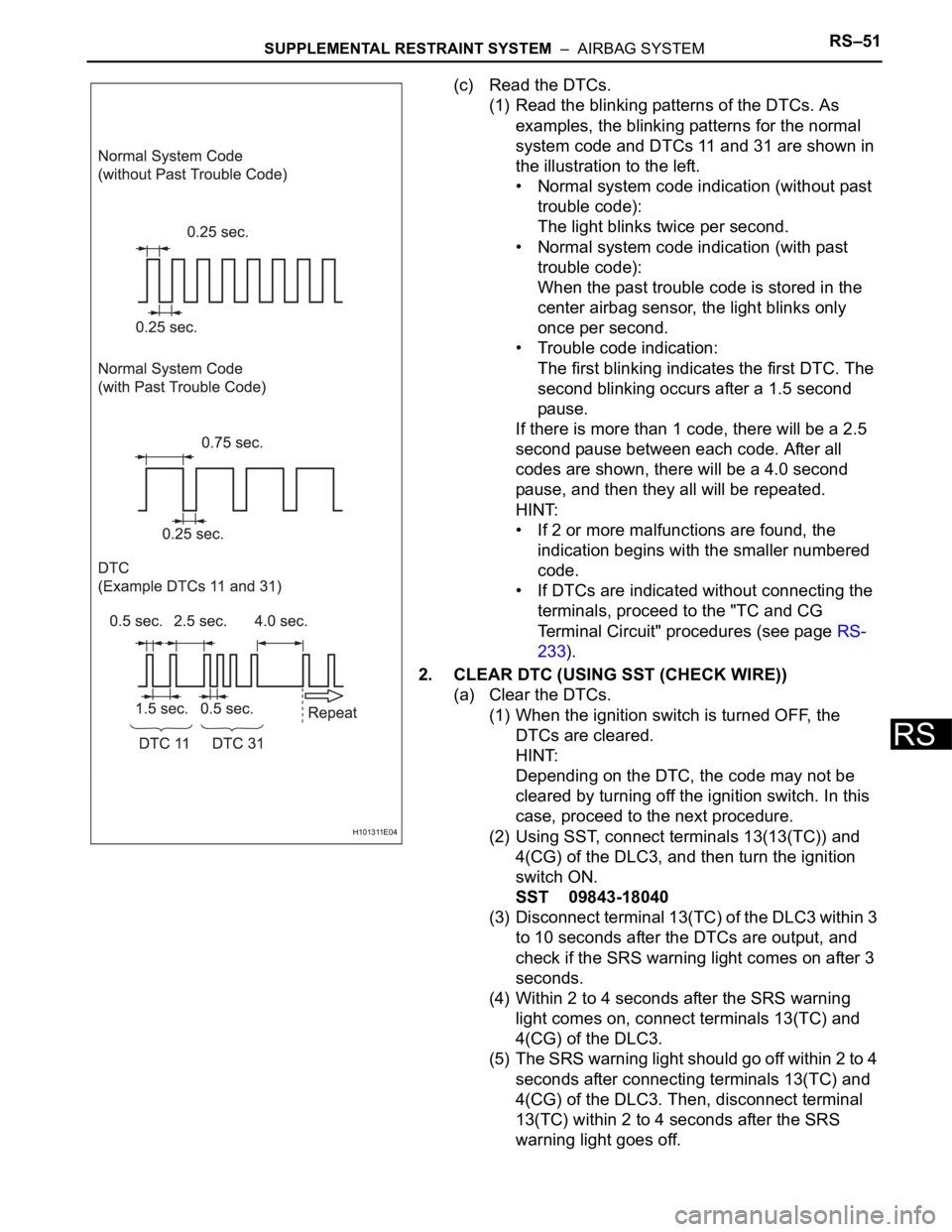
(1) Read the blinking patterns of the DTCs. As
examples, the blinking patterns for the normal
system code and DTCs 11 and 31 are shown in
the illustration to the left.
• Normal system code indication (without past
trouble code):
The light blinks twice per second.
• Normal system code indication (with past
trouble code):
When the past trouble code is stored in the
center airbag sensor, the light blinks only
once per second.
• Trouble code indication:
The first blinking indicates the first DTC. The
second blinking occurs after a 1.5 second
pause.
If there is more than 1 code, there will be a 2.5
second pause between each code. After all
codes are shown, there will be a 4.0 second
pause, and then they all will be repeated.
HINT:
• If 2 or more malfunctions are found, the
indication begins with the smaller numbered
code.
• If DTCs are indicated without connecting the
terminals, proceed to the "TC and CG
Terminal Circuit" procedures (see page RS-
233).
2. CLEAR DTC (USING SST (CHECK WIRE))
(a) Clear the DTCs.
(1) When the ignition switch is turned OFF, the
DTCs are cleared.
HINT:
Depending on the DTC, the code may not be
cleared by turning off the ignition switch. In this
case, proceed to the next procedure.
(2) Using SST, connect terminals 13(13(TC)) and
4(CG) of the DLC3, and then turn the ignition
switch ON.
SST 09843-18040
(3) Disconnect terminal 13(TC) of the DLC3 within 3
to 10 seconds after the DTCs are output, and
check if the SRS warning light comes on after 3
seconds.
(4) Within 2 to 4 seconds after the SRS warning
light comes on, connect terminals 13(TC) and
4(CG) of the DLC3.
(5) The SRS warning light should go off within 2 to 4
seconds after connecting terminals 13(TC) and
4(CG) of the DLC3. Then, disconnect terminal
13(TC) within 2 to 4 seconds after the SRS
warning light goes off.
H101311E04
Page 1702 of 2000

SUPPLEMENTAL RESTRAINT SYSTEM – AIRBAG SYSTEMRS–53
RS
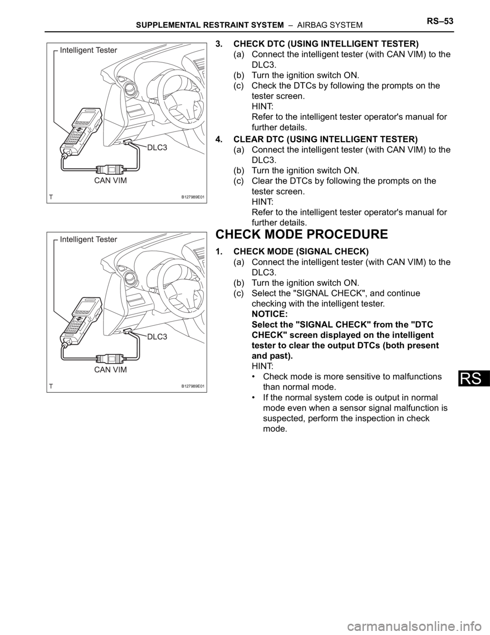
3. CHECK DTC (USING INTELLIGENT TESTER)
(a) Connect the intelligent tester (with CAN VIM) to the
DLC3.
(b) Turn the ignition switch ON.
(c) Check the DTCs by following the prompts on the
tester screen.
HINT:
Refer to the intelligent tester operator's manual for
further details.
4. CLEAR DTC (USING INTELLIGENT TESTER)
(a) Connect the intelligent tester (with CAN VIM) to the
DLC3.
(b) Turn the ignition switch ON.
(c) Clear the DTCs by following the prompts on the
tester screen.
HINT:
Refer to the intelligent tester operator's manual for
further details.
CHECK MODE PROCEDURE
1. CHECK MODE (SIGNAL CHECK)
(a) Connect the intelligent tester (with CAN VIM) to the
DLC3.
(b) Turn the ignition switch ON.
(c) Select the "SIGNAL CHECK", and continue
checking with the intelligent tester.
NOTICE:
Select the "SIGNAL CHECK" from the "DTC
CHECK" screen displayed on the intelligent
tester to clear the output DTCs (both present
and past).
HINT:
• Check mode is more sensitive to malfunctions
than normal mode.
• If the normal system code is output in normal
mode even when a sensor signal malfunction is
suspected, perform the inspection in check
mode.
B127989E01
B127989E01
Page 1703 of 2000

RS–54SUPPLEMENTAL RESTRAINT SYSTEM – AIRBAG SYSTEM
RS
DATA LIST / ACTIVE TEST
1. READ DATA LIST
HINT:
Using the intelligent tester's Data List allows switch,
sensor, actuator and other item values to be read without
removing any parts. Reading the Data List early in
troubleshooting in one way to save time.
(a) Connect the intelligent tester (with CAN VIM) to the
DLC3.
(b) Turn the ignition switch ON.
(c) Read the Data List according to the display on the
tester.
Center airbag sensor
Item Measure Item / Range (Display) Normal Condition Diagnostic Note
D SEAT POSITIONSeat position (Driver side)/
FORWARD: Seat position
forward
BKWARD: Seat position
backward
FAIL: Failure detectedFORWARD/BKWARD -
PASSENGER CLASSFront passenger classification/
NG: Data is not determined
OFF: Vacant
CHILD: Child (Less than 36 kg
[79.37 lb]) seated
AF05: Adult (36 to 54 kg [79.37 to
119.05 lb]) seated
AM50: Adult (More than 54 kg
[119.05 lb]) seated
FAIL: Failure detectedNG/OFF/CHILD/AF05/AM50/FAIL -
D BUCKLE SWBuckle switch (Driver side)/
UNSET: Seat belt not fastened
SET: Seat belt fastened
NG: Data not determinedUNSET/SET -
P BUCKLE SWBuckle switch (Front passenger
side)/
UNSET: Seat belt not fastened
SET: Seat belt fastened
NG: Data not determinedUNSET/SET -
DISPLAY TYPEDisplay type identification
information/
LR: Display indicated by LH/RH
DP: Display indicated by Driver/
PassengerDP -
PAST CODESNumber of past DTCs / Min.: 0,
Max.: 2550-
Page 1708 of 2000

SUPPLEMENTAL RESTRAINT SYSTEM – AIRBAG SYSTEMRS–59
RS
DESCRIPTION
The center airbag sensor consists of the airbag sensor, the safing sensor, the drive circuit, the diagnosis
circuit and the ignition control.
If the center airbag sensor receives signals from the airbag sensor, it determines whether or not the SRS
should be activated.
DTC B1000/31 is recorded when a malfunction is detected in the center airbag sensor.
HINT:
When a malfunction code is displayed simultaneously with DTC B1000/31, repair the malfunction
indicated by this code (except DTC B1000/31) first.
INSPECTION PROCEDURE
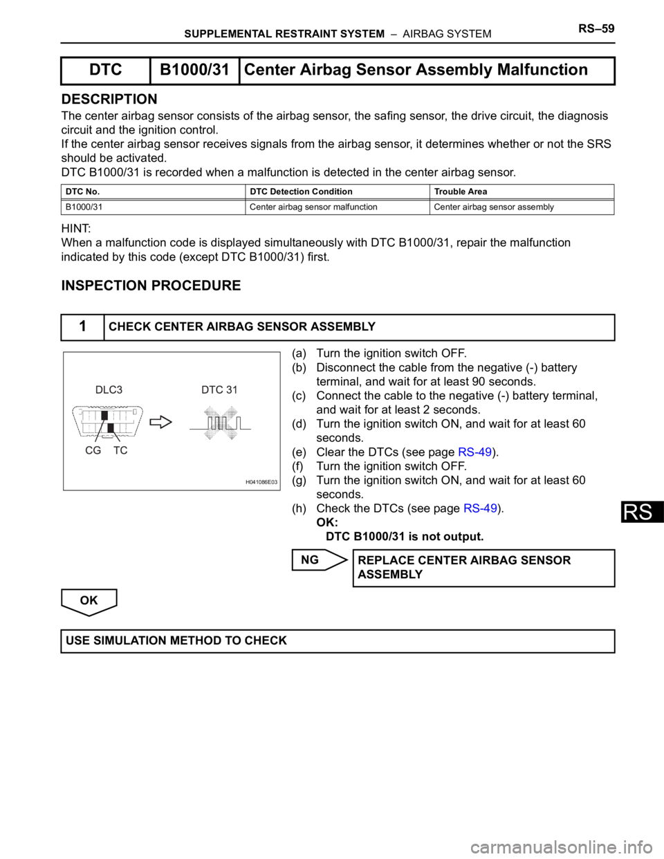
(a) Turn the ignition switch OFF.
(b) Disconnect the cable from the negative (-) battery
terminal, and wait for at least 90 seconds.
(c) Connect the cable to the negative (-) battery terminal,
and wait for at least 2 seconds.
(d) Turn the ignition switch ON, and wait for at least 60
seconds.
(e) Clear the DTCs (see page RS-49).
(f) Turn the ignition switch OFF.
(g) Turn the ignition switch ON, and wait for at least 60
seconds.
(h) Check the DTCs (see page RS-49).
OK:
DTC B1000/31 is not output.
NG
OK
DTC B1000/31 Center Airbag Sensor Assembly Malfunction
DTC No. DTC Detection Condition Trouble Area
B1000/31 Center airbag sensor malfunction Center airbag sensor assembly
1CHECK CENTER AIRBAG SENSOR ASSEMBLY
H041086E03
REPLACE CENTER AIRBAG SENSOR
ASSEMBLY
USE SIMULATION METHOD TO CHECK
Page 1710 of 2000
SUPPLEMENTAL RESTRAINT SYSTEM – AIRBAG SYSTEMRS–61
RS
WIRING DIAGRAM
INSPECTION PROCEDURE
(a) Turn the ignition switch OFF.
(b) Disconnect the cable from the negative (-) battery
terminal, and wait for at least 90 seconds.
(c) Check that the connectors are properly connected to the
center airbag sensor and the front airbag sensor RH.
OK:
The connectors are connected.
NG
1CHECK CONNECTION OF CONNECTOR
C123527E01
CONNECT CONNECTOR
Page 1713 of 2000
RS–64SUPPLEMENTAL RESTRAINT SYSTEM – AIRBAG SYSTEM
RS
(a) Connect the cable to the negative (-) battery terminal,
and wait for at least 2 seconds.
(b) Turn the ignition switch ON.
(c) Measure the voltage of the wire harness side connector.
Standard voltage
NG
OK
4CHECK FRONT AIRBAG SENSOR RH CIRCUIT (TO B+)
C128663E01
Tester Connection Specified Condition
E45-29 (+SR) -Body ground Below 1 V
E45-27 (-SR) - Body ground Below 1 V
Go to step 9
Page 1714 of 2000
SUPPLEMENTAL RESTRAINT SYSTEM – AIRBAG SYSTEMRS–65
RS
(a) Turn the ignition switch OFF.
(b) Disconnect the cable from the negative (-) battery
terminal, and wait for at least 90 seconds.
(c) Measure the resistance of the wire harness side
connector.
Standard resistance
NG
OK
5CHECK FRONT AIRBAG SENSOR RH CIRCUIT (TO GROUND)
C128663E01
Tester Connection Specified Condition
E45-29 (+SR) - Body ground 1 M
or higher
E45-27 (-SR) - Body ground 1 M
or higher
Go to step 10