2006 TOYOTA RAV4 ignition
[x] Cancel search: ignitionPage 1752 of 2000

SB–14SEAT BELT – SEAT BELT WARNING SYSTEM
SB
DESCRIPTION
When the ignition switch is ON, the center airbag sensor transmits front seat inner belt status signals to
the combination meter through the CAN bus line. If the driver seat belt is not fastened, the combination
meter blinks the driver side seat belt warning light. If the seat belt is fastened, the warning light goes off.
NOTICE:
The seat belt warning system uses the CAN bus line. Before troubleshooting the seat belt warning
system, perform "COMMUNICATION FUNCTION CHECK" by following "HOW TO PROCEED WITH
TROUBLESHOOTING" to confirm that the communication systems are normal.
Driver Side Seat Belt Warning Light does not Operate
Page 1755 of 2000

SEAT BELT – SEAT BELT WARNING SYSTEMSB–17
SB
DESCRIPTION
When the ignition switch is ON, the center airbag sensor transmits front seat inner belt status signals to
the combination meter through the CAN bus line. If the front passenger seat belt is not fastened, the
heater control panel (automatic A/C) or clock (manual A/C) blinks the front passenger seat belt warning
light. If the seat belt is fastened, the warning light goes off.
NOTICE:
The seat belt warning system uses the CAN bus line. Before troubleshooting the seat belt warning
system, perform "COMMUNICATION FUNCTION CHECK" by following "HOW TO PROCEED WITH
TROUBLESHOOTING" to confirm that the communication systems are normal.
Front Passenger Side Seat Belt Warning Light Malfunction
Page 1757 of 2000

SEAT BELT – SEAT BELT WARNING SYSTEMSB–19
SB
INSPECTION PROCEDURE
(a) Select the Active Test, use the intelligent tester to
generate a control command, and then check that the
seat belt warning light operates.
Center airbag sensor:
OK:
Passenger side seat belt warning light operates
normally.
OK
NG
(a) Check system.
B
A
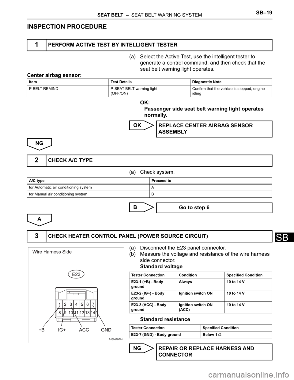
(a) Disconnect the E23 panel connector.
(b) Measure the voltage and resistance of the wire harness
side connector.
Standard voltage
Standard resistance
NG
1PERFORM ACTIVE TEST BY INTELLIGENT TESTER
Item Test Details Diagnostic Note
P-BELT REMIND P-SEAT BELT warning light
(OFF/ON)Confirm that the vehicle is stopped, engine
idling
REPLACE CENTER AIRBAG SENSOR
ASSEMBLY
2CHECK A/C TYPE
A/C type Proceed to
for Automatic air conditioning system A
for Manual air conditioning system B
Go to step 6
3CHECK HEATER CONTROL PANEL (POWER SOURCE CIRCUIT)
B130079E01
Tester Connection Condition Specified Condition
E23-1 (+B) - Body
groundAlways 10 to 14 V
E23-2 (IG+) - Body
groundIgnition switch ON 10 to 14 V
E23-3 (ACC) - Body
groundIgnition switch ON
(ACC)10 to 14 V
Tester Connection Specified Condition
E23-7 (GND) - Body ground Below 1
REPAIR OR REPLACE HARNESS AND
CONNECTOR
Page 1759 of 2000

SEAT BELT – SEAT BELT WARNING SYSTEMSB–21
SB
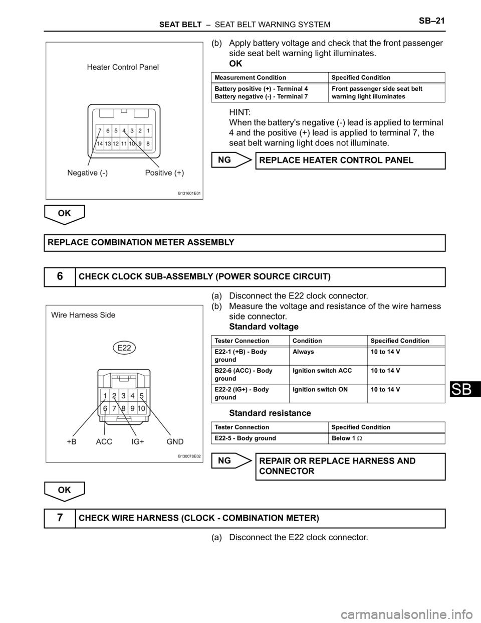
(b) Apply battery voltage and check that the front passenger
side seat belt warning light illuminates.
OK
HINT:
When the battery's negative (-) lead is applied to terminal
4 and the positive (+) lead is applied to terminal 7, the
seat belt warning light does not illuminate.
NG
OK
(a) Disconnect the E22 clock connector.
(b) Measure the voltage and resistance of the wire harness
side connector.
Standard voltage
Standard resistance
NG
OK
(a) Disconnect the E22 clock connector.
B131601E01
Measurement Condition Specified Condition
Battery positive (+) - Terminal 4
Battery negative (-) - Terminal 7Front passenger side seat belt
warning light illuminates
REPLACE HEATER CONTROL PANEL
REPLACE COMBINATION METER ASSEMBLY
6CHECK CLOCK SUB-ASSEMBLY (POWER SOURCE CIRCUIT)
B130078E02
Tester Connection Condition Specified Condition
E22-1 (+B) - Body
groundAlways 10 to 14 V
B22-6 (ACC) - Body
groundIgnition switch ACC 10 to 14 V
E22-2 (IG+) - Body
groundIgnition switch ON 10 to 14 V
Tester Connection Specified Condition
E22-5 - Body ground Below 1
REPAIR OR REPLACE HARNESS AND
CONNECTOR
7CHECK WIRE HARNESS (CLOCK - COMBINATION METER)
Page 1778 of 2000

ENGINE IMMOBILISER – ENGINE IMMOBILISER SYSTEMEI–7
EI
HINT:
• In this mode, a maximum of 3 key codes for 2
master keys and 1 sub-key can be registered.
The master keys and sub-key can be registered
in any order because the transponder key ECU
can distinguish between different types of keys.
• New key codes must be registered with the
battery connected. The ignition switch can be
either ON or OFF.
• When a new transponder key ECU is installed,
key codes must be registered in the transponder
key ECU.
HINT:
• The new key code registration mode can be
deliberately ended by following procedure A or B
below when the battery is connected, and at
least 1 key code for the master key has been
registered.
(a) Insert the key into the ignition key cylinder and
turn the intelligent tester on.
(b) Follow the instructions on the intelligent tester
screen to end the new key code registration
mode.
(c) New key code registration mode ends.
• When the engine immobiliser system is operating
normally and the key is pulled out, the security
indicator light blinks continuously.
• If the new key code registration fails, code 2-1 is
output by the security indicator light. Trying to re-
register an already registered key causes code
2-2 to be output when the key is inserted. If the
number of registered key codes exceeds the
limit, code 2-3 is output by the security indicator
light. The output details are shown below.
Procedure Security Indicator Light Condition
1. START-
HINT:
Until first key is inserted
2. Insert key into the ignition key cylinder BLINKING
3. Select following items on the tester:
(1) IMMOBILISER
(2) ID UTILITY
(3) IMMOB CODE REG
HINT:
After above operation, proceed to next step in accordance with
prompts on tester screenON
HINT:
Within 2 minutes
OFF for 1 second and then ON
4. Remove the key and then push NEXT button on tester ON
5. Insert master key or sub-key to be registered OFF for 1 second and then ON
6. Remove key and then push NEXT button on tester ON
7. Insert a master key or sub-key to be registeredOFF for 1 second and then ON
OFF
HINT:
0.5 seconds after turning ON
8. Remove key BLINKING
9. END
Page 1780 of 2000

ENGINE IMMOBILISER – ENGINE IMMOBILISER SYSTEMEI–9
EI
3. REGISTRATION OF ADDITIONAL KEY (PROCEDURE
"A")
HINT:
• A maximum of 5 master key codes and 3 sub-key
codes can be registered.
• Additional key code registration mode ends if each
step is not completed within the specified time.
• When proceeding to the next step while the timer is
running, the timer is reset and begins the countdown
for the next step.
• When the ignition key cylinder or the ignition key
cylinder set is replaced, remove the transmitter
module from the original master key. Then install this
transmitter module to a new key and use the new key
as the master key. If necessary, use this master key to
register other keys.
NOTICE:
When the ignition key cylinder has been replaced,
locking and unlocking doors are possible with the
new master key once the transmitter module from
the original master key has been transferred to it.
However, the new master key will not be able to lock
and unlock doors through the door key cylinder.
Keep the original master key. If the new master key's
transmitter module battery fails, the original master
key can be used to lock and unlock doors through
the door key cylinder.
(a) Additional key code registration
Condition:
At least one key code must be registered in the
transponder key ECU.
ProcedureTime
(Operation completion time)Security Indicator Light Condition
1. START -BLINKING
HINT:
Until first key is inserted
2. Insert previously registered master key into
ignition key cylinder, turn ignition switch to ON
position, and turn intelligent tester on
-OFF
3. Select the following items on the tester:
(1) IMMOBILISER
(2) ID UTILITY
(3) IMMOB CODE REGON
4. Remove master key and then push NEXT
button on tester. Immediately after above
operation, insert previously registered master
key into ignition key cylinder, turn ignition
switch to ON position, and then push NEXT
button on tester.Within 120 seconds BLINKING
ON
5. Remove master key and then push NEXT
button on testerWithin 20 seconds
HINT:
After the tester instruction.ON
6. Insert key to be registered into ignition key
cylinderWithin 10 seconds. BLINKING
Page 1781 of 2000

EI–10ENGINE IMMOBILISER – ENGINE IMMOBILISER SYSTEM
EI
HINT:
• If the key is removed within 60 seconds in step 6,
the additional key code registration mode is
canceled.
• A brief outline of the procedures for key code
registration is shown above. For more detailed
information, refer to the intelligent tester screen's
instructions.
• When the engine immobiliser system is operating
normally and the key is pulled out, the security
indicator light blinks continuously.
• If the additional key code registration fails, code
2-1 is output by the security indicator light. Trying
to reregister a previously registered key causes
code 2-2 to be output when the key is inserted. If
the number of registered key codes exceeds the
limit, code 2-3 is output by the security indicator
light. The output details are shown in procedure
"B".
4. ERASURE OF KEY CODE (PROCEDURE "D")
HINT:
All key codes are erased except for the master key,
which is used for erasing the key codes. In order to use a
key whose code has been erased, a new key code must
be registered.
(a) Erasure of key code
Condition:
At least two key codes must be registered in the
transponder key ECU.
7. After 60 seconds, key is registered
HINT:
Security indicator light goes off
-OFF
8. Remove key and then push NEXT button
on testerBLINKING
9. Tester screen displays number of registered key
10. ENDProcedureTime
(Operation completion time)Security Indicator Light Condition
ProcedureTime
(Operation completion time)Security Indicator Light Condition
1. START -BLINKING
HINT:
Until first key is inserted
2. Insert previously registered master key into
ignition key cylinder, turn ignition switch to ON
position, and turn intelligent tester on
-OFF
3. Select following items on tester:
(1) IMMOBILISER
(2) ID UTILITY
(3) IMMOB CODE ERSOFF
4. Remove key and then push NEXT button
on tester. Immediately after above operation,
insert previously registered master key into
ignition key cylinder, turn ignition switch to ON
position, and then push NEXT button on
tester.Within 120 seconds BLINKING
ON for 1 second then OFF
Page 1782 of 2000

ENGINE IMMOBILISER – ENGINE IMMOBILISER SYSTEMEI–11
EI
HINT:
• To cancel erasure mode after the erasure
request is sent from the tester to the ECU, leave
the master key inserted until the timer times out.
• A brief outline of the procedures for key code
erasure is shown above. For more detailed
information, refer to the intelligent tester screen's
instructions.
• When the engine immobiliser system is operating
normally and the key is pulled out, the security
indicator light blinks continuously.
5. ECU - ECM COMMUNICATION ID REGISTRATION
(PROCEDURE "C")
NOTICE:
• The ECU communication ID should be registered
when the transponder key ECU and / or ECM is
replaced in order to match the ECU - ECM
communication ID.
• The engine cannot be started unless the ECU -
ECM communication ID matches.
• Do not disconnect the battery while the ECU -
ECM communication ID is being set.
• Do not turn the ignition switch from ON to OFF 20
times or more before setting the ECU - ECM
communication ID. If this operation is likely to be
performed 20 times or more, disconnect the
negative battery terminal cable in order to avoid
engine start disablement. Failure to do so will
result in the engine not starting unless the
transponder key ECU is replaced with a new one.
(a) After replacing the transponder key ECU
(1) Register the key code(s) by following the new
key code registration procedure (procedure
"B").
(2) Using SST, connect the TC and CG terminals
of the DLC3 before inserting the key into the
key cylinder.
SST 09843-18040
5. Remove master keyWithin 10 seconds
HINT:
After tester instructionBLINKING
6. ENDProcedureTime
(Operation completion time)Security Indicator Light Condition