Page 1019 of 2000

U140F AUTOMATIC TRANSAXLE – DIFFERENTIAL CASEAX–259
AX
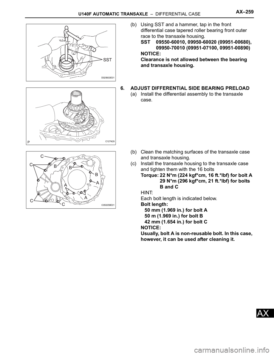
(b) Using SST and a hammer, tap in the front
differential case tapered roller bearing front outer
race to the transaxle housing.
SST 09550-60010, 09950-60020 (09951-00680),
09950-70010 (09951-07100, 09951-00890)
NOTICE:
Clearance is not allowed between the bearing
and transaxle housing.
6. ADJUST DIFFERENTIAL SIDE BEARING PRELOAD
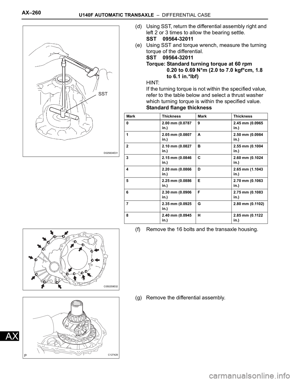
(a) Install the differential assembly to the transaxle
case.
(b) Clean the matching surfaces of the transaxle case
and transaxle housing.
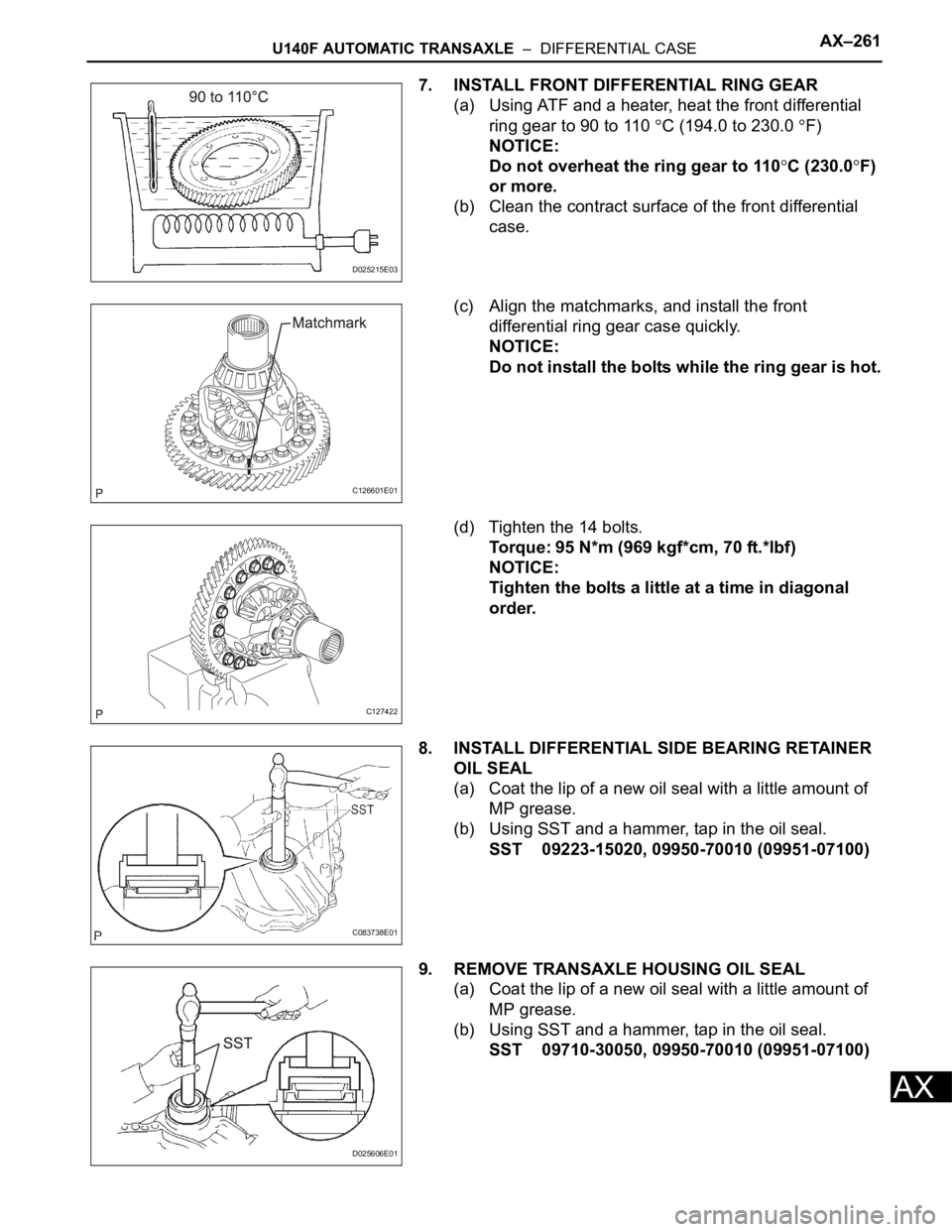
(c) Install the transaxle housing to the transaxle case
and tighten them with the 16 bolts
Torque: 22 N*m (224 kgf*cm, 16 ft.*lbf) for bolt A
29 N*m (296 kgf*cm, 21 ft.*lbf) for bolts
B and C
HINT:
Each bolt length is indicated below.
Bolt length:
50 mm (1.969 in.) for bolt A
50 m (1.969 in.) for bolt B
42 mm (1.654 in.) for bolt C
NOTICE:
Usually, bolt A is non-reusable bolt. In this case,
however, it can be used after cleaning it.
D025603E01
C127429
C050259E01
Page 1020 of 2000

AX–260U140F AUTOMATIC TRANSAXLE – DIFFERENTIAL CASE
AX
(d) Using SST, return the differential assembly right and
left 2 or 3 times to allow the bearing settle.
SST 09564-32011
(e) Using SST and torque wrench, measure the turning
torque of the differential.
SST 09564-32011
Torque: Standard turning torque at 60 rpm
0.20 to 0.69 N*m (2.0 to 7.0 kgf*cm, 1.8
to 6.1 in.*lbf)
HINT:
If the turning torque is not within the specified value,
refer to the table below and select a thrust washer
which turning torque is within the specified value.
Standard flange thickness
(f) Remove the 16 bolts and the transaxle housing.
(g) Remove the differential assembly.
D025604E01
Mark Thickness Mark Thickness
0 2.00 mm (0.0787
in.)9 2.45 mm (0.0965
in.)
1 2.05 mm (0.0807
in.)A 2.50 mm (0.0984
in.)
2 2.10 mm (0.0827
in.)B 2.55 mm (0.1004
in.)
3 2.15 mm (0.0846
in.)C 2.60 mm (0.1024
in.)
4 2.20 mm (0.0866
in.)D 2.65 mm (1.1043
in.)
5 2.25 mm (0.0886
in.)E 2.70 mm (0.1063
in.)
6 2.30 mm (0.0906
in.)F 2.75 mm (0.1083
in.)
7 2.35 mm (0.0925
in.)G 2.80 mm (0.1102)
8 2.40 mm (0.0945
in.)H 2.85 mm (0.1122
in.)
C050259E02
C127429
Page 1021 of 2000

U140F AUTOMATIC TRANSAXLE – DIFFERENTIAL CASEAX–261
AX
7. INSTALL FRONT DIFFERENTIAL RING GEAR
(a) Using ATF and a heater, heat the front differential
ring gear to 90 to 110
C (194.0 to 230.0 F)
NOTICE:
Do not overheat the ring gear to 110
C (230.0F)
or more.
(b) Clean the contract surface of the front differential
case.
(c) Align the matchmarks, and install the front
differential ring gear case quickly.
NOTICE:
Do not install the bolts while the ring gear is hot.
(d) Tighten the 14 bolts.
Torque: 95 N*m (969 kgf*cm, 70 ft.*lbf)
NOTICE:
Tighten the bolts a little at a time in diagonal
order.
8. INSTALL DIFFERENTIAL SIDE BEARING RETAINER
OIL SEAL
(a) Coat the lip of a new oil seal with a little amount of
MP grease.
(b) Using SST and a hammer, tap in the oil seal.
SST 09223-15020, 09950-70010 (09951-07100)
9. REMOVE TRANSAXLE HOUSING OIL SEAL
(a) Coat the lip of a new oil seal with a little amount of
MP grease.
(b) Using SST and a hammer, tap in the oil seal.
SST 09710-30050, 09950-70010 (09951-07100)
D025215E03
C126601E01
C127422
C083738E01
D025606E01
Page 1022 of 2000
AX–6U151E AUTOMATIC TRANSAXLE – AUTOMATIC TRANSAXLE SYSTEM
AX
SYSTEM DIAGRAM
The configuration of the electronic control system in the
U151E automatic transaxle is as shown in the following chart.
C136233E01
Page 1023 of 2000
U151E AUTOMATIC TRANSAXLE – AUTOMATIC TRANSAXLE SYSTEMAX–7
AX
C116585E02
Page 1024 of 2000
AX–8U151E AUTOMATIC TRANSAXLE – AUTOMATIC TRANSAXLE SYSTEM
AX
C136234E01
Page 1025 of 2000
U151E AUTOMATIC TRANSAXLE – AUTOMATIC TRANSAXLE SYSTEMAX–9
AX
C136235E01
Page 1026 of 2000
AX–10U151E AUTOMATIC TRANSAXLE – AUTOMATIC TRANSAXLE SYSTEM
AX
SYSTEM DESCRIPTION
1. SYSTEM DESCRIPTION
(a) The Electronic Controlled Automatic Transaxle
(ECT) is an automatic transaxle that electronically
controls shift timing using the Engine Control
Module (ECM). The ECM detects electrical signals
that indicate engine and driving conditions, and
controls the shift point based on driver habits and
road conditions. As a result, fuel efficiency and
power transaxle performance are improved.
Shift shock is reduced by controlling the engine and
transaxle simultaneously.
In addition, the ECT has the following features:
• Diagnostic function.
• Fail-safe function when a malfunction occurs.