Page 392 of 2000
SERVICE SPECIFICATIONS – GF1A TRANSFERSS–69
SS
TORQUE SPECIFICATIONS
Part Tightened N*m kgf*cm ft.*lbf
Breather oil deflector x transfer
case6.5 66 58
Output shaft x Transfer gear nut 360 3700 266
Driven pinion front bearing x
Transfer case38 390 28
No. 1 transfer case cover x
transfer case47 480 35
Transfer drain plug x transfer
case49 500 36
Transfer drain plug x transfer
case49 500 36
Transfer & Transaxle setting stud
bolt x transfer case39 400 29
Transfer assembly x transaxle 69 700 51
4WD Control ECU x Body 4.5 46 40
Page 404 of 2000

AXLE – FRONT AXLE HUBAH–7
AH
REMOVAL
(2005/11-2006/01)
HINT:
• Use the same procedures for the RH side and LH side.
• The procedures listed below are for the LH side.
1. REMOVE FRONT WHEEL
2. DRAIN AUTOMATIC TRANSAXLE FLUID
(a) Drain the automatic transaxle fluid for U140F (see
page AX-147).
(b) Drain the automatic transaxle fluid for U241E (see
page AX-146).
3. DISCONNECT CABLE FROM NEGATIVE BATTERY
TERMINAL
CAUTION:
Wait at least 90 seconds after disconnecting the
cable from the negative (-) battery terminal to
prevent airbag and seat belt pretensioner activation.
4. REMOVE FRONT AXLE HUB NUT
(a) Using SST and a hammer, unstake the staked part
of the nut.
SST 09930-00010
NOTICE:
Loosen the staked part of the nut completely,
otherwise the screw of the drive shaft may be
damaged.
(b) While applying the brakes, remove the lock axle hub
nut.
5. REMOVE FRONT SPEED SENSOR LH (See page BC-
191)
6. REMOVE FRONT DISC BRAKE CYLINDER
ASSEMBLY LH (See page BR-40)
7. REMOVE FRONT DISC (See page BR-42)
8. DISCONNECT TIE ROD END SUB-ASSEMBLY LH
(See page PS-42)
9. DISCONNECT FRONT SUSPENSION NO. 1 LOWER
ARM SUB-ASSEMBLY LH
(a) Remove the bolt and 2 nuts.
(b) Disconnect the lower arm from the ball joint.
C129483E01
C127531
Page 579 of 2000
EM–222AZ-FE ENGINE MECHANICAL – TIMING CHAIN
EM
REMOVAL
1. DISCONNECT CABLE FROM NEGATIVE BATTERY
TERMINAL
CAUTION:
Wait at least 90 seconds after disconnecting the
cable from the negative (-) battery terminal to
prevent airbag and seat belt pretensioner activation.
2. REMOVE RADIATOR SUPPORT OPENING COVER
3. REMOVE FRONT WHEEL RH
4. REMOVE NO. 1 ENGINE UNDER COVER
5. REMOVE FRONT FENDER APRON RH
6. REMOVE NO. 1 ENGINE COVER
(a) Remove the 2 nuts and cover.
7. DRAIN ENGINE OIL (See page LU-4)
8. REMOVE FRONT EXHAUST PIPE (See page EX-3)
9. REMOVE FRONT SUSPENSION MEMBER
REINFORCEMENT RH (See page EM-6)
10. REMOVE FAN AND GENERATOR V BELT (See page
EM-6)
11. REMOVE GENERATOR ASSEMBLY (See page CH-9)
12. REMOVE RADIATOR RESERVOIR
(a) Remove the 2 bolts and radiator reservoir.
13. REMOVE ENGINE MOUNTING INSULATOR RH
(a) Remove the bolt of the wire harness protector.
(b) Disconnect the 2 clamps of the engine wire.
A112206
A124838
A098189E02
Page 601 of 2000

2AZ-FE ENGINE MECHANICAL – CYLINDER HEADEM–57
EM
REMOVAL
1. DISCHARGE FUEL SYSTEM PRESSURE (See page
FU-9)
2. DISCONNECT CABLE FROM NEGATIVE BATTERY
TERMINAL
CAUTION:
Wait at least 90 seconds after disconnecting the
cable from the negative (-) battery terminal to
prevent airbag and seat belt pretensioner activation.
3. REMOVE RADIATOR SUPPORT OPENING COVER
4. REMOVE FRONT WHEEL RH
5. REMOVE NO. 1 ENGINE UNDER COVER
6. REMOVE FRONT FENDER APRON RH
7. REMOVE NO. 1 ENGINE COVER (See page EM-22)
8. DRAIN ENGINE COOLANT (See page CO-6)
9. DRAIN ENGINE OIL (See page LU-4)
10. REMOVE AIR CLEANER CAP (See page ES-411)
11. REMOVE THROTTLE BODY (See page ES-412)
12. REMOVE FUEL DELIVERY PIPE SUB-ASSEMBLY
(See page FU-10)
13. REMOVE INTAKE MANIFOLD (See page ES-419)
14. REMOVE INTAKE MANIFOLD INSULATOR (See page
ES-420)
15. REMOVE FRONT EXHAUST PIPE (See page EX-3)
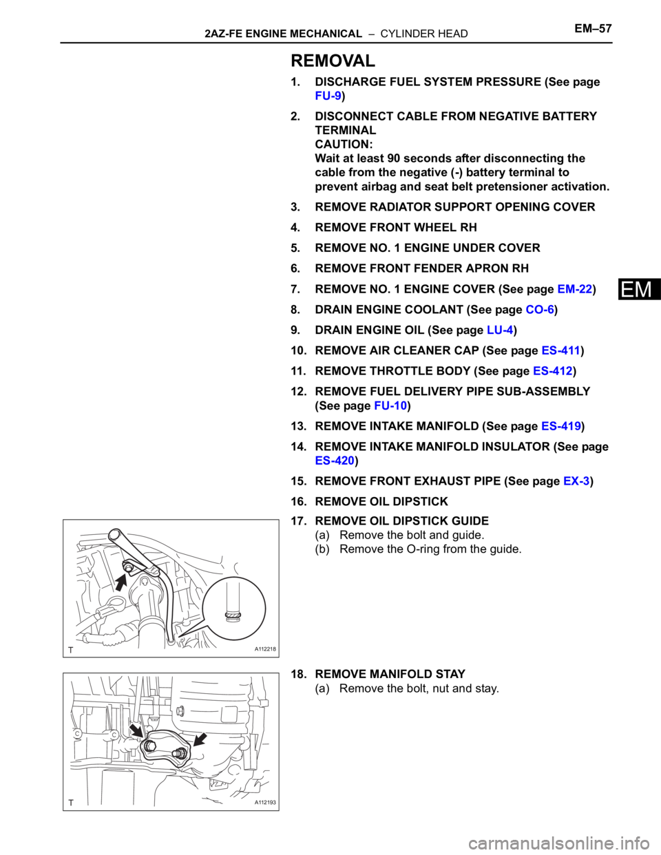
16. REMOVE OIL DIPSTICK
17. REMOVE OIL DIPSTICK GUIDE
(a) Remove the bolt and guide.
(b) Remove the O-ring from the guide.
18. REMOVE MANIFOLD STAY
(a) Remove the bolt, nut and stay.
A112218
A112193
Page 633 of 2000

EM–982AZ-FE ENGINE MECHANICAL – ENGINE ASSEMBLY
EM
REMOVAL
1. DISCHARGE FUEL SYSTEM PRESSURE (See page
FU-9)
2. DISCONNECT CABLE FROM NEGATIVE BATTERY
TERMINAL
CAUTION:
Wait at least 90 seconds after disconnecting the
cable from the negative (-) battery terminal to
prevent airbag and seat belt pretensioner activation.
3. REMOVE HOOD SUB-ASSEMBLY (See page ED-4)
4. REMOVE RADIATOR SUPPORT OPENING COVER
5. REMOVE BATTERY CLAMP SUB-ASSEMBLY
(a) Loosen the bolt and nut, and remove the battery
clamp.
6. REMOVE BATTERY
7. REMOVE BATTERY TRAY
8. REMOVE FRONT WHEEL
9. REMOVE NO. 1 ENGINE UNDER COVER
10. REMOVE NO. 2 ENGINE UNDER COVER
11. REMOVE FRONT FENDER APRON RH
12. REMOVE NO. 1 ENGINE COVER (See page EM-22)
13. DRAIN ENGINE COOLANT (See page CO-6)
14. DRAIN AUTOMATIC TRANSAXLE FLUID
(a) Drain automatic transaxle fluid for U241E (2WD)
(see page AX-146).
(b) Drain automatic transaxle fluid for U140F (4WD)
(see page AX-147).
15. REMOVE RADIATOR ASSEMBLY
(a) Remove the radiator (see page CO-29).
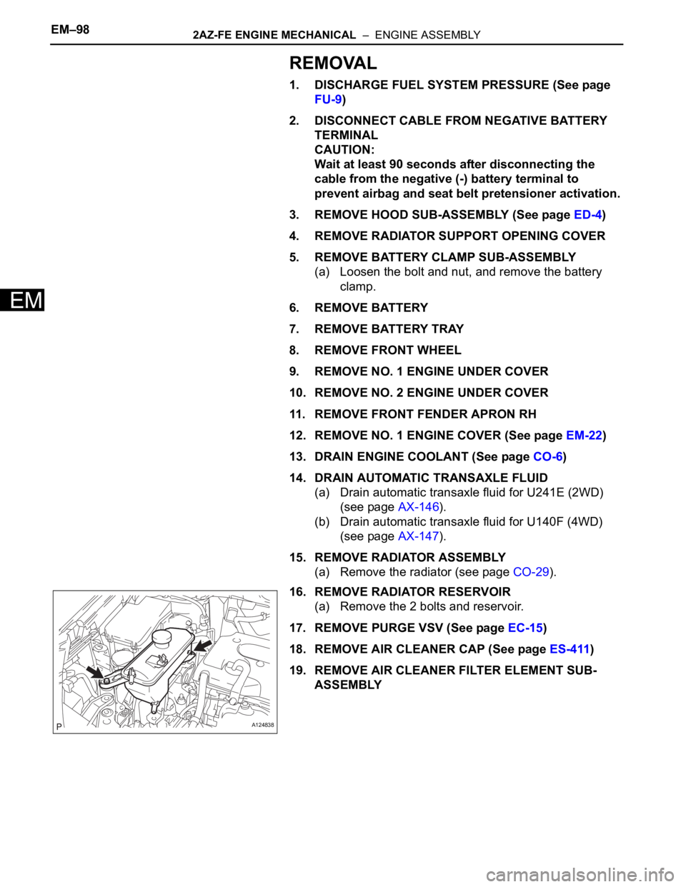
16. REMOVE RADIATOR RESERVOIR
(a) Remove the 2 bolts and reservoir.
17. REMOVE PURGE VSV (See page EC-15)
18. REMOVE AIR CLEANER CAP (See page ES-411)
19. REMOVE AIR CLEANER FILTER ELEMENT SUB-
ASSEMBLY
A124838
Page 652 of 2000

2AZ-FE ENGINE MECHANICAL – ENGINE UNITEM–125
EM
31. REMOVE OIL PAN DRAIN PLUG
(a) Remove the oil pan drain plug and gasket.
32. REMOVE OIL PAN SUB-ASSEMBLY (See page EM-
24)
33. REMOVE CRANKSHAFT PULLEY (See page EM-25)
34. REMOVE NO. 1 CHAIN TENSIONER ASSEMBLY (See
page EM-26)
35. REMOVE TIMING CHAIN COVER SUB-ASSEMBLY
(See page EM-26)
36. REMOVE NO. 1 CRANKSHAFT POSITION SENSOR
PLATE
37. REMOVE TIMING CHAIN GUIDE (See page EM-28)
38. REMOVE CHAIN TENSIONER SLIPPER (See page
EM-28)
39. REMOVE NO. 1 CHAIN VIBRATION DAMPER (See
page EM-28)
40. REMOVE CHAIN SUB-ASSEMBLY
41. REMOVE CRANKSHAFT TIMING SPROCKET
42. REMOVE NO. 2 CHAIN SUB-ASSEMBLY (See page
EM-29)
43. REMOVE OIL PUMP DRIVE GEAR
44. REMOVE OIL PUMP ASSEMBLY (See page LU-12)
45. REMOVE CAMSHAFT
(a) Using several steps, uniformly loosen and remove
the 20 bearing cap bolts in the sequence shown in
the illustration.
(b) Remove the 10 bearing caps, then remove the
camshaft and No. 2 camshaft.
46. REMOVE CYLINDER HEAD SUB-ASSEMBLY (See
page EM-62)
A128176
A132571
A128185
A128186
F050596E02
Page 742 of 2000
2GR-FE ENGINE MECHANICAL – ENGINE UNITEM–105
EM
REASSEMBLY
1. INSTALL NO. 1 OIL NOZZLE SUB-ASSEMBLY
(a) Using a 5 mm hexagon wrench, install the 3 oil
nozzles with the bolts.
Torque: 9.0 N*m (92 kgf*cm, 80 in.*lbf)
2. INSTALL CYLINDER BLOCK WATER DRAIN COCK
SUB-ASSEMBLY
(a) Apply adhesive around the drain cocks.
Adhesive:
Toyota Genuine Adhesive 1324, Three Bond
1324 or Equivalent
(b) Install the cylinder block water drain cocks.
(1) Temporarily install the drain cocks.
Torque: 25 N*m (255 kgf*cm, 18 ft.*lbf)
A132040E01
A129732
A076531E01
Page 841 of 2000
2AZ-FE COOLING – WATER PUMPCO–11
CO
REMOVAL
1. DISCONNECT CABLE FROM NEGATIVE BATTERY
TERMINAL
CAUTION:
Wait at least 90 seconds after disconnecting the
cable from the negative (-) battery terminal to
prevent airbag and seat belt pretensioner activation.
2. REMOVE NO. 1 ENGINE UNDER COVER
3. REMOVE FRONT FENDER APRON RH
4. REMOVE RADIATOR SUPPORT OPENING COVER
5. DRAIN ENGINE COOLANT (See page CO-6)
6. REMOVE FRONT SUSPENSION MEMBER
REINFORCEMENT RH (See page EM-6)
7. REMOVE FAN AND GENERATOR V BELT (See page
EM-6)
8. REMOVE GENERATOR ASSEMBLY (See page CH-9)
9. REMOVE WATER PUMP PULLEY
(a) Using SST, remove the 4 bolts and water pump
pulley.
SST 09960-10010 (09962-01000, 09963-00700)
10. REMOVE WATER PUMP ASSEMBLY
(a) Remove the clamp of the crankshaft position sensor
from the water pump.
(b) Disconnect the wire of the crankshaft position
sensor from the clamp bracket.
(c) Remove the 4 bolts, 2 nuts and clamp bracket.
A098715E03
A094516E01
B012052E03