Page 1447 of 2000

DIFFERENTIAL – REAR DIFFERENTIAL CARRIER ASSEMBLYDF–43
DF
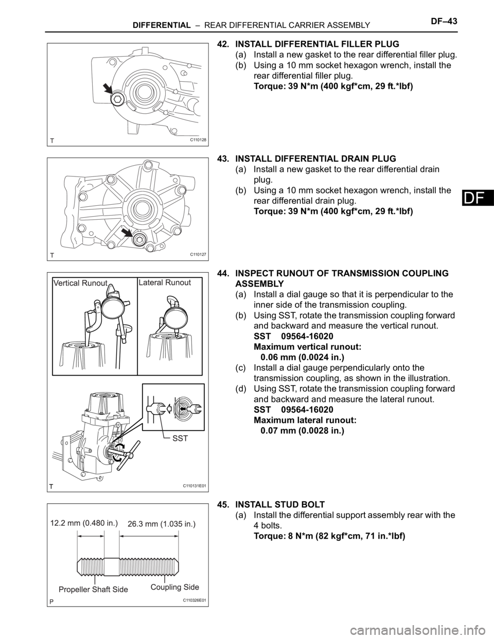
42. INSTALL DIFFERENTIAL FILLER PLUG
(a) Install a new gasket to the rear differential filler plug.
(b) Using a 10 mm socket hexagon wrench, install the
rear differential filler plug.
Torque: 39 N*m (400 kgf*cm, 29 ft.*lbf)
43. INSTALL DIFFERENTIAL DRAIN PLUG
(a) Install a new gasket to the rear differential drain
plug.
(b) Using a 10 mm socket hexagon wrench, install the
rear differential drain plug.
Torque: 39 N*m (400 kgf*cm, 29 ft.*lbf)
44. INSPECT RUNOUT OF TRANSMISSION COUPLING
ASSEMBLY
(a) Install a dial gauge so that it is perpendicular to the
inner side of the transmission coupling.
(b) Using SST, rotate the transmission coupling forward
and backward and measure the vertical runout.
SST 09564-16020
Maximum vertical runout:
0.06 mm (0.0024 in.)
(c) Install a dial gauge perpendicularly onto the
transmission coupling, as shown in the illustration.
(d) Using SST, rotate the transmission coupling forward
and backward and measure the lateral runout.
SST 09564-16020
Maximum lateral runout:
0.07 mm (0.0028 in.)
45. INSTALL STUD BOLT
(a) Install the differential support assembly rear with the
4 bolts.
Torque: 8 N*m (82 kgf*cm, 71 in.*lbf)
C110128
C110127
C110131E01
C110326E01
Page 1450 of 2000

AXLE – FRONT AXLE HUBAH–9
AH
REMOVAL
(2006/01- )
HINT:
• Use the same procedures for the RH side and LH side.
• The procedures listed below are the LH side.
1. REMOVE FRONT WHEEL
2. DRAIN AUTOMATIC TRANSAXLE FLUID
(a) Drain the automatic transaxle fluid for U140F (see
page AX-147).
(b) Drain the automatic transaxle fluid for U241E (see
page AX-146).
(c) Drain the automatic transaxle fluid for U151E (see
page AX-172).
(d) Drain the automatic transaxle fluid for U151F (see
page AX-173).
3. DISCONNECT CABLE FROM NEGATIVE BATTERY
TERMINAL
CAUTION:
Wait at least 90 seconds after disconnecting the
cable from the negative (-) battery terminal to
prevent airbag and seat belt pretensioner activation.
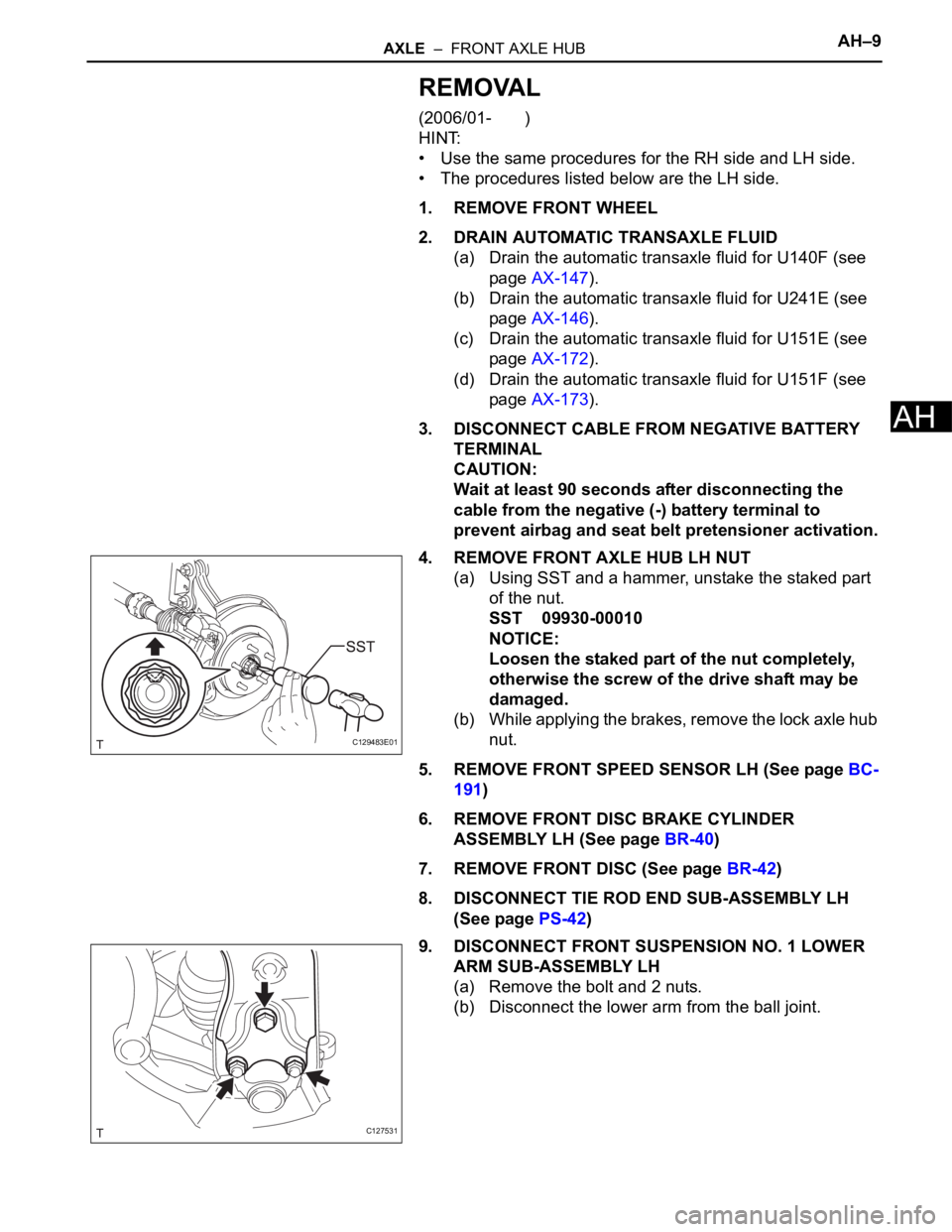
4. REMOVE FRONT AXLE HUB LH NUT
(a) Using SST and a hammer, unstake the staked part
of the nut.
SST 09930-00010
NOTICE:
Loosen the staked part of the nut completely,
otherwise the screw of the drive shaft may be
damaged.
(b) While applying the brakes, remove the lock axle hub
nut.
5. REMOVE FRONT SPEED SENSOR LH (See page BC-
191)
6. REMOVE FRONT DISC BRAKE CYLINDER
ASSEMBLY LH (See page BR-40)
7. REMOVE FRONT DISC (See page BR-42)
8. DISCONNECT TIE ROD END SUB-ASSEMBLY LH
(See page PS-42)
9. DISCONNECT FRONT SUSPENSION NO. 1 LOWER
ARM SUB-ASSEMBLY LH
(a) Remove the bolt and 2 nuts.
(b) Disconnect the lower arm from the ball joint.
C129483E01
C127531
Page 1662 of 2000

AIR CONDITIONING – COMPRESSOR AND PULLEY (for 2AZ-FE)AC–217
AC
INSTALLATION
1. ADJUST ADJUST COMPRESSOR OIL
(a) When replacing the compressor and magnetic
clutch with a new one, gradually discharge the
refrigerant gas from the service valve, and drain the
following amount of oil from the new compressor
and magnetic clutch before installation.
Standard:
(Oil capacity inside the new compressor and
magnetic clutch: 130 + 15 cc (4.6 + 0.51 fl.oz.) )
-(Remaining oil amount in the removed
compressor and magnetic clutch) = (Oil
amount to be removed from the new
compressor when replacing)
NOTICE:
• When checking the compressor oil level,
observe the precautions on the cooler
removal/installation.
• If a new compressor and magnetic clutch is
installed without removing some oil
remaining in the pipes of the vehicle, the oil
amount will be too large. This prevents heat
exchange in the refrigerant cycle and causes
refrigerant failure.
• If the volume of oil remaining in the removed
compressor and magnetic clutch is too small,
check for oil leakage.
• Be sure to use ND-OIL 8 or equivalent for
compressor oil.
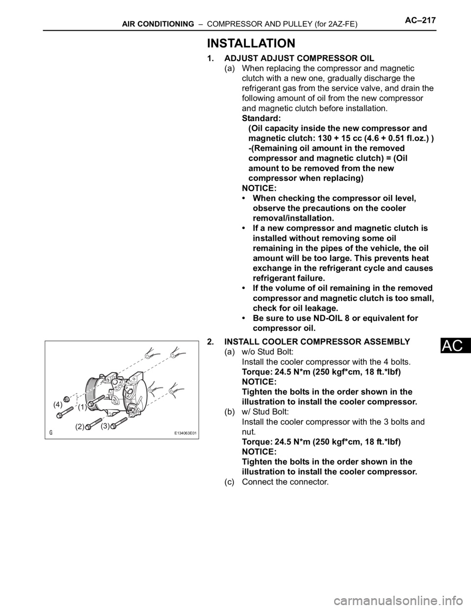
2. INSTALL COOLER COMPRESSOR ASSEMBLY
(a) w/o Stud Bolt:
Install the cooler compressor with the 4 bolts.
Torque: 24.5 N*m (250 kgf*cm, 18 ft.*lbf)
NOTICE:
Tighten the bolts in the order shown in the
illustration to install the cooler compressor.
(b) w/ Stud Bolt:
Install the cooler compressor with the 3 bolts and
nut.
Torque: 24.5 N*m (250 kgf*cm, 18 ft.*lbf)
NOTICE:
Tighten the bolts in the order shown in the
illustration to install the cooler compressor.
(c) Connect the connector.
E134063E01