Page 847 of 2000
2AZ-FE COOLING – RADIATORCO–29
CO
REMOVAL
1. DISCONNECT CABLE FROM NEGATIVE BATTERY
TERMINAL
CAUTION:
Wait at least 90 seconds after disconnecting the
cable from the negative (-) battery terminal to
prevent airbag and seat belt pretensioner activation.
2. REMOVE RADIATOR SUPPORT OPENING COVER
3. REMOVE BATTERY CLAMP
(a) Remove the bolt, nut and clamp.
4. REMOVE BATTERY
5. REMOVE NO. 1 ENGINE UNDER COVER
6. DRAIN ENGINE COOLANT (See page CO-6)
7. REMOVE RADIATOR GRILLE SUB-ASSEMBLY (See
page ET-6)
8. DISCONNECT HOOD LOCK SWITCH CONNECTOR
9. DISCONNECT NO. 1 WATER BY-PASS HOSE
(a) Disconnect the hose from the radiator reservoir.
10. DISCONNECT NO. 5 WATER BY-PASS HOSE
(a) Disconnect the hose from the radiator.
11. REMOVE NO. 1 WATER BY-PASS PIPE
(a) Disconnect the pipe from the No. 1 radiator hose.
(b) Remove the 2 bolts and the pipe.
12. DISCONNECT COOLING FAN MOTOR HARNESS
(a) Disconnect the 2 fan motor connectors from the 2
fan motors.
A112308
A112333E01
Page 856 of 2000
2GR-FE COOLING – WATER PUMPCO–13
CO
6. REMOVE NO. 2 IDLER PULLEY SUB-ASSEMBLY
(a) Remove the bolt, No. 2 idler pulley cover plate and
No. 2 idler pulley.
7. REMOVE V-RIBBED BELT TENSIONER ASSEMBLY
(a) Remove the 5 bolts and V-ribbed belt tensioner
assembly.
8. REMOVE WATER PUMP ASSEMBLY
(a) Remove the 16 bolts, water pump and water pump
gasket.
INSPECTION
1. INSPECT WATER PUMP ASSEMBLY
(a) Visually check the drain hole for coolant leakage.
If leakage is found, replace the water pump
assembly.
(b) Turn the pulley, and then check that the water pump
bearing moves smoothly without making a clicking
noise.
If it does not move smoothly, replace the water
pump assembly.
INSTALLATION
1. INSTALL WATER PUMP ASSEMBLY
(a) Install a new water pump gasket and the water
pump with the 16 bolts.
Torque: 21 N*m (214 kgf*cm, 15 ft.*lbf) for bolt A
9.1 N*m (93 kgf*cm, 81 in.*lbf) for bolt B
and C
A132445
A138913
A132448
A096655E01
A132448E01
Page 859 of 2000
2GR-FE COOLING – THERMOSTATCO–19
CO
REMOVAL
1. REMOVE FRONT WHEEL RH
2. REMOVE NO. 1 ENGINE UNDER COVER (See page
EM-21)
3. REMOVE ENGINE UNDER COVER REAR RH (See
page EM-21)
4. REMOVE FRONT SUSPENSION MEMBER
REINFORCEMENT RH (See page EM-7)
5. DRAIN ENGINE COOLANT (See page CO-8)
6. REMOVE V-BANK COVER SUB-ASSEMBLY (See
page EM-21)
7. REMOVE RADIATOR SUPPORT OPENING COVER
(See page EM-22)
8. REMOVE RADIATOR RESERVOIR TANK
(a) Remove the 2 bolts and radiator reservoir.
9. REMOVE FAN AND GENERATOR V BELT (See page
EM-8)
10. REMOVE ENGINE MOUNTING INSULATOR RH
(a) Remove the 5 bolts, 2 nuts and engine mounting
insulator RH.
11. REMOVE FRONT NO. 1 ENGINE MOUNTING
BRACKET LH (See page CO-12)
12. REMOVE NO. 2 IDLER PULLEY SUB-ASSEMBLY
(a) Remove the bolt, No. 2 idler pulley cover plate and
No. 2 idler pulley.
13. DISCONNECT NO. 2 RADIATOR HOSE
A132441E01
A136837
A094887E01
Page 883 of 2000

2GR-FE LUBRICATION – OIL PUMPLU–23
LU
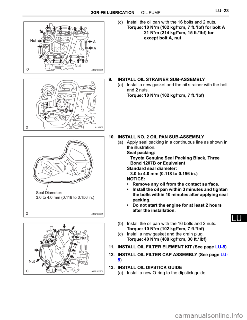
(c) Install the oil pan with the 16 bolts and 2 nuts.
Torque: 10 N*m (102 kgf*cm, 7 ft.*lbf) for bolt A
21 N*m (214 kgf*cm, 15 ft.*lbf) for
except bolt A, nut
9. INSTALL OIL STRAINER SUB-ASSEMBLY
(a) Install a new gasket and the oil strainer with the bolt
and 2 nuts.
Torque: 10 N*m (102 kgf*cm, 7 ft.*lbf)
10. INSTALL NO. 2 OIL PAN SUB-ASSEMBLY
(a) Apply seal packing in a continuous line as shown in
the illustration.
Seal packing:
Toyota Genuine Seal Packing Black, Three
Bond 1207B or Equivalent
Standard seal diameter:
3.0 to 4.0 mm (0.118 to 0.156 in.)
NOTICE:
• Remove any oil from the contact surface.
• Install the oil pan within 3 minutes and tighten
the bolts within 10 minutes after applying seal
packing.
• Do not start the engine for at least 2 hours
after the installation.
(b) Install the oil pan with the 16 bolts and 2 nuts.
Torque: 10 N*m (102 kgf*cm, 7 ft.*lbf)
(c) Install a new gasket and the drain plug.
Torque: 40 N*m (408 kgf*cm, 30 ft.*lbf)
11. INSTALL OIL FILTER ELEMENT KIT (See page LU-5)
12. INSTALL OIL FILTER CAP ASSEMBLY (See page LU-
5)
13. INSTALL OIL DIPSTICK GUIDE
(a) Install a new O-ring to the dipstick guide.
A132109E01
A132108
A132138E01
A132107E01
Page 976 of 2000

AX–144U140F AUTOMATIC TRANSAXLE – DIFFERENTIAL OIL SEAL
AX
REPLACEMENT
1. REPLACE TRANSAXLE HOUSING OIL SEAL LH
(a) Drain the automatic transaxle fluid.
(1) Remove the drain plug and gasket, and drain
AT F.
(2) Install a new gasket and drain plug.
Torque: 47 N*m (479 kgf*cm, 35 ft.*lbf)
(b) Remove the front drive shaft LH (see page DS-41).
(c) Remove the transaxle housing oil seal LH.
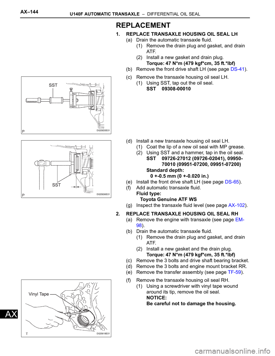
(1) Using SST, tap out the oil seal.
SST 09308-00010
(d) Install a new transaxle housing oil seal LH.
(1) Coat the lip of a new oil seal with MP grease.
(2) Using SST and a hammer, tap in the oil seal.
SST 09726-27012 (09726-02041), 09950-
70010 (09951-07200, 09951-07200)
Standard depth:
0 +-0.5 mm (0 +-0.020 in.)
(e) Install the front drive shaft LH (see page DS-65).
(f) Add automatic transaxle fluid.
Fluid type:
Toyota Genuine ATF WS
(g) Inspect the transaxle fluid level (see page AX-102).
2. REPLACE TRANSAXLE HOUSING OIL SEAL RH
(a) Remove the engine with transaxle (see page EM-
98).
(b) Drain the automatic transaxle fluid.
(1) Remove the drain plug and gasket, and drain
AT F.
(2) Install a new gasket and the drain plug.
Torque: 47 N*m (479 kgf*cm, 35 ft.*lbf)
(c) Remove the 3 bolts and drive shaft bearing bracket.
(d) Remove the 3 bolts and engine mount bracket RR.
(e) Remove the transfer assembly (see page TF-59).
(f) Remove the transaxle housing oil seal RH.
(1) Using a screwdriver with vinyl tape wound
around its tip, remove the oil seal.
NOTICE:
Be careful not to damage the housing.
D025835E01
D025836E01
D025618E01
Page 1162 of 2000

AX–170U151F AUTOMATIC TRANSAXLE – DIFFERENTIAL OIL SEAL
AX
REPLACEMENT
1. REPLACE TRANSAXLE HOUSING OIL SEAL LH
(a) Drain the automatic transaxle fluid.
(1) Remove the drain plug and gasket, and drain
the ATF.
(2) Install a new gasket and drain plug.
Torque: 47 N*m (479 kgf*cm, 35 ft.*lbf)
(b) Remove the front drive shaft LH (see page DS-41).
(c) Remove the transaxle housing oil seal LH.
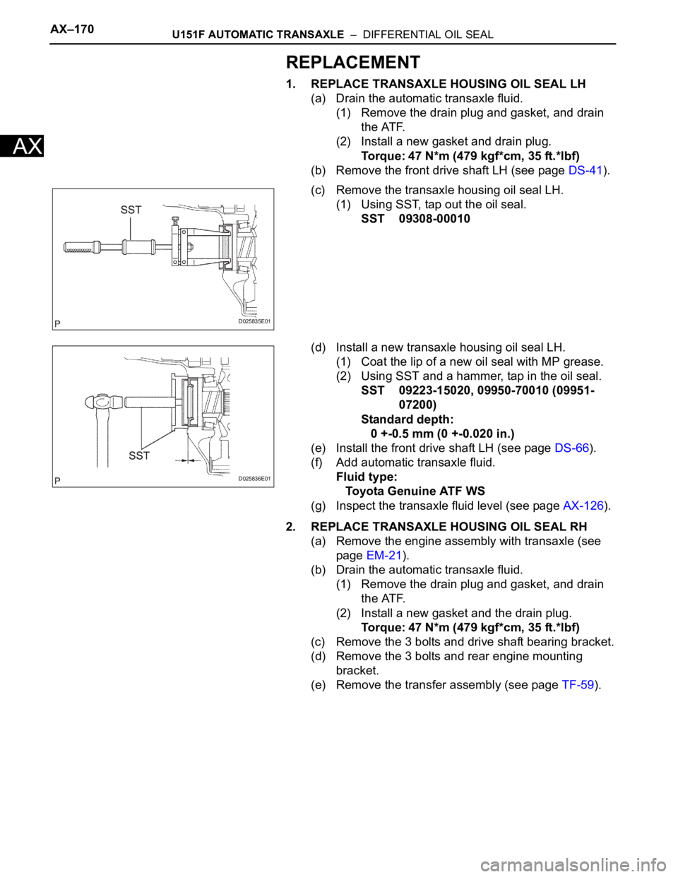
(1) Using SST, tap out the oil seal.
SST 09308-00010
(d) Install a new transaxle housing oil seal LH.
(1) Coat the lip of a new oil seal with MP grease.
(2) Using SST and a hammer, tap in the oil seal.
SST 09223-15020, 09950-70010 (09951-
07200)
Standard depth:
0 +-0.5 mm (0 +-0.020 in.)
(e) Install the front drive shaft LH (see page DS-66).
(f) Add automatic transaxle fluid.
Fluid type:
Toyota Genuine ATF WS
(g) Inspect the transaxle fluid level (see page AX-126).
2. REPLACE TRANSAXLE HOUSING OIL SEAL RH
(a) Remove the engine assembly with transaxle (see
page EM-21).
(b) Drain the automatic transaxle fluid.
(1) Remove the drain plug and gasket, and drain
the ATF.
(2) Install a new gasket and the drain plug.
Torque: 47 N*m (479 kgf*cm, 35 ft.*lbf)
(c) Remove the 3 bolts and drive shaft bearing bracket.
(d) Remove the 3 bolts and rear engine mounting
bracket.
(e) Remove the transfer assembly (see page TF-59).
D025835E01
D025836E01
Page 1422 of 2000
DF–18DIFFERENTIAL – REAR DIFFERENTIAL CARRIER ASSEMBLY
DF
REMOVAL
1. DRAIN DIFFERENTIAL OIL
2. REMOVE REAR WHEEL
3. REMOVE TAILPIPE ASSEMBLY
(a) Remove the tailpipe (see page EX-2).
4. REMOVE CENTER EXHAUST PIPE ASSEMBLY
(a) Remove the center pipe (see page EX-2).
5. REMOVE PROPELLER WITH CENTER BEARING
SHAFT ASSEMBLY (See page PR-3)
6. REMOVE REAR SUSPENSION MEMBER BRACE LH
(a) Remove the 2 bolts and brace from the suspension
member.
7. REMOVE REAR SUSPENSION MEMBER BRACE RH
HINT:
Use the same procedures described for the LH side.
8. REMOVE REAR DIFFERENTIAL CARRIER SUB-
ASSEMBLY
(a) Disconnect the harness clamp.
(b) Remove the breather tube.
(c) Disconnect the connector.
C127572
C127575
Page 1425 of 2000
DIFFERENTIAL – REAR DIFFERENTIAL CARRIER ASSEMBLYDF–21
DF
DISASSEMBLY
1. FIX DIFFERENTIAL CARRIER SUB-ASSEMBLY
(a) Fix the rear differential carrier in place with the
overhaul attachment.
2. REMOVE STUD BOLT
(a) Remove the 4 stud bolts from the transmission
coupling.
3. REMOVE DIFFERENTIAL DRAIN PLUG
(a) Using a 10 mm socket hexagon wrench, remove the
rear differential drain plug and gasket.
4. REMOVE DIFFERENTIAL FILLER PLUG
(a) Using a 10 mm socket hexagon wrench, remove the
rear differential filler plug and gasket.
5. REMOVE DIFFERENTIAL CARRIER COVER PLUG
(a) Using an 8 mm socket hexagon wrench, remove
rear differential carrier cover plug.
6. REMOVE DIFFERENTIAL CARRIER COVER
BREATHER PLUG
(a) Using a chisel and hammer, slightly lift up the rear
differential carrier cover breather plug.
(b) Using a screwdriver, lightly pry up and remove the
rear differential carrier cover breather plug.
C110127
C110128
C110129
C110130