2006 SUZUKI SX4 AIR
[x] Cancel search: AIRPage 1365 of 1556
Downloaded from www.Manualslib.com manuals search engine Instrumentation / Driver Info. / Horn: 9C-13
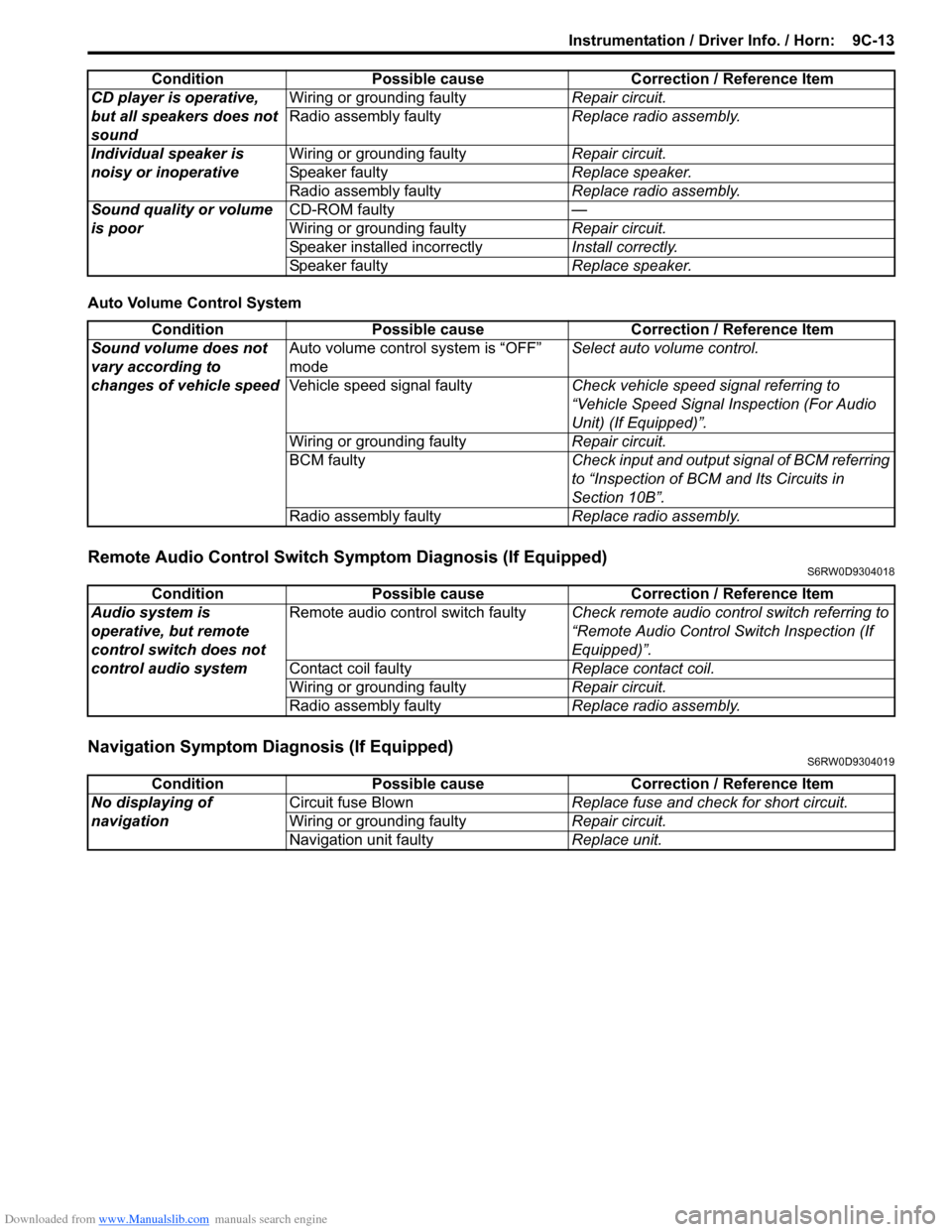
Auto Volume Control System
Remote Audio Control Switch Symptom Diagnosis (If Equipped)S6RW0D9304018
Navigation Symptom Diagnosis (If Equipped)S6RW0D9304019
CD player is operative,
but all speakers does not
soundWiring or grounding faultyRepair circuit.
Radio assembly faultyReplace radio assembly.
Individual speaker is
noisy or inoperativeWiring or grounding faultyRepair circuit.
Speaker faultyReplace speaker.
Radio assembly faultyReplace radio assembly.
Sound quality or volume
is poorCD-ROM faulty—
Wiring or grounding faultyRepair circuit.
Speaker installed incorrectlyInstall correctly.
Speaker faultyReplace speaker. Condition Possible cause Correction / Reference Item
Condition Possible cause Correction / Reference Item
Sound volume does not
vary according to
changes of vehicle speedAuto volume control system is “OFF”
modeSelect auto volume control.
Vehicle speed signal faultyCheck vehicle speed signal referring to
“Vehicle Speed Signal Inspection (For Audio
Unit) (If Equipped)”.
Wiring or grounding faultyRepair circuit.
BCM faultyCheck input and output signal of BCM referring
to “Inspection of BCM and Its Circuits in
Section 10B”.
Radio assembly faultyReplace radio assembly.
Condition Possible cause Correction / Reference Item
Audio system is
operative, but remote
control switch does not
control audio systemRemote audio control switch faultyCheck remote audio control switch referring to
“Remote Audio Control Switch Inspection (If
Equipped)”.
Contact coil faultyReplace contact coil.
Wiring or grounding faultyRepair circuit.
Radio assembly faultyReplace radio assembly.
Condition Possible cause Correction / Reference Item
No displaying of
navigationCircuit fuse BlownReplace fuse and check for short circuit.
Wiring or grounding faultyRepair circuit.
Navigation unit faultyReplace unit.
Page 1366 of 1556
Downloaded from www.Manualslib.com manuals search engine 9C-14 Instrumentation / Driver Info. / Horn:
Repair Instructions
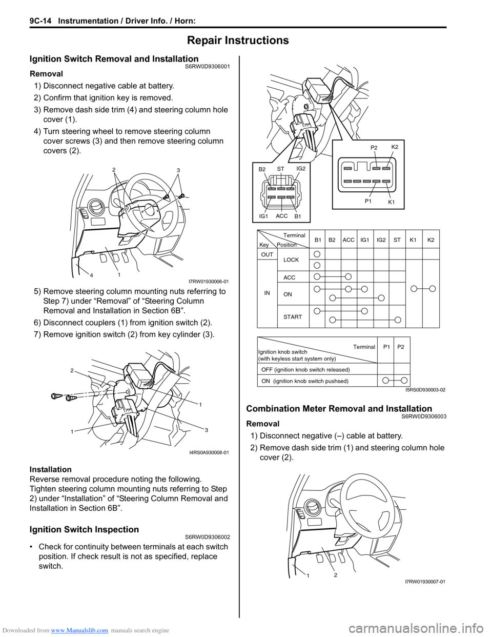
Ignition Switch Removal and InstallationS6RW0D9306001
Removal
1) Disconnect negative cable at battery.
2) Confirm that ignition key is removed.
3) Remove dash side trim (4) and steering column hole
cover (1).
4) Turn steering wheel to remove steering column
cover screws (3) and then remove steering column
covers (2).
5) Remove steering column mounting nuts referring to
Step 7) under “Removal” of “Steering Column
Removal and Installation in Section 6B”.
6) Disconnect couplers (1) from ignition switch (2).
7) Remove ignition switch (2) from key cylinder (3).
Installation
Reverse removal procedure noting the following.
Tighten steering column mounting nuts referring to Step
2) under “Installation” of “Steering Column Removal and
Installation in Section 6B”.
Ignition Switch InspectionS6RW0D9306002
• Check for continuity between terminals at each switch
position. If check result is not as specified, replace
switch.
Combination Meter Removal and InstallationS6RW0D9306003
Removal
1) Disconnect negative (–) cable at battery.
2) Remove dash side trim (1) and steering column hole
cover (2).
2
3
1
4I7RW01930006-01
11
2
3
I4RS0A930008-01
PositionTerminal
LOCK
ACC
ON
START OUT
INK2 K1 ST IG2 IG1 ACC B1 B2
Ignition knob switch
(with keyless start system only)
ACC
IG1IG2
ST
B2
B1K2
K1
P2
P1
Terminal
OFF (ignition knob switch released)
ON (ignition knob switch pushsed)P1 P2
Key
I5RS0D930003-02
21I7RW01930007-01
Page 1369 of 1556
Downloaded from www.Manualslib.com manuals search engine Instrumentation / Driver Info. / Horn: 9C-17
Outside Air Temperature Sensor Removal and
Installation (If Equipped)
S6RW0D9306013
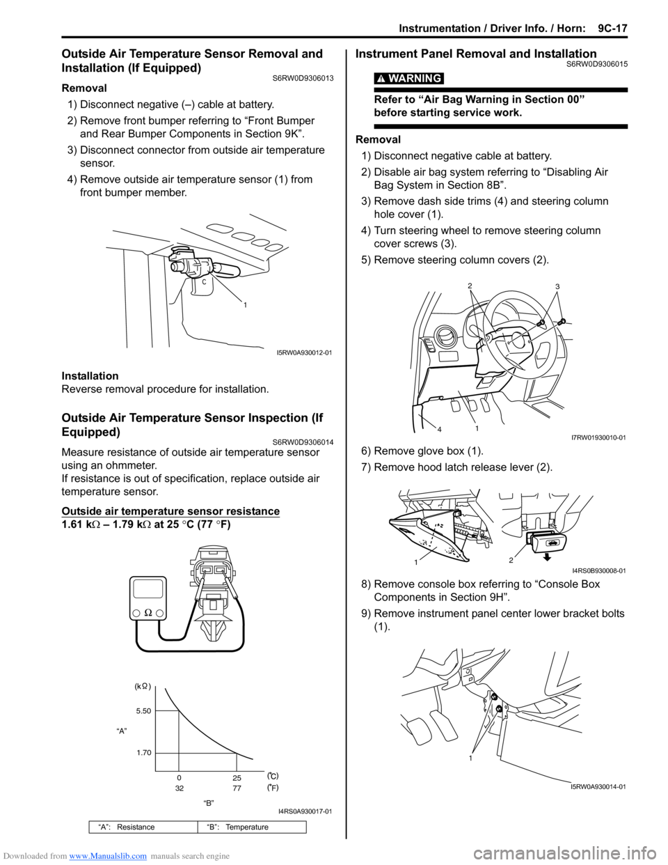
Removal
1) Disconnect negative (–) cable at battery.
2) Remove front bumper referring to “Front Bumper
and Rear Bumper Components in Section 9K”.
3) Disconnect connector from outside air temperature
sensor.
4) Remove outside air temperature sensor (1) from
front bumper member.
Installation
Reverse removal procedure for installation.
Outside Air Temperature Sensor Inspection (If
Equipped)
S6RW0D9306014
Measure resistance of outside air temperature sensor
using an ohmmeter.
If resistance is out of specification, replace outside air
temperature sensor.
Outside air temperature sensor resistance
1.61 kΩ – 1.79 kΩ at 25 °C (77 °F)
Instrument Panel Removal and InstallationS6RW0D9306015
WARNING!
Refer to “Air Bag Warning in Section 00”
before starting service work.
Removal
1) Disconnect negative cable at battery.
2) Disable air bag system referring to “Disabling Air
Bag System in Section 8B”.
3) Remove dash side trims (4) and steering column
hole cover (1).
4) Turn steering wheel to remove steering column
cover screws (3).
5) Remove steering column covers (2).
6) Remove glove box (1).
7) Remove hood latch release lever (2).
8) Remove console box referring to “Console Box
Components in Section 9H”.
9) Remove instrument panel center lower bracket bolts
(1).
“A”: Resistance “B”: Temperature
1
I5RW0A930012-01
“B” “A”5.50
1.70
0
3225
77
F
I4RS0A930017-01
2
3
1
4I7RW01930010-01
2
1I4RS0B930008-01
1
I5RW0A930014-01
Page 1370 of 1556
Downloaded from www.Manualslib.com manuals search engine 9C-18 Instrumentation / Driver Info. / Horn:
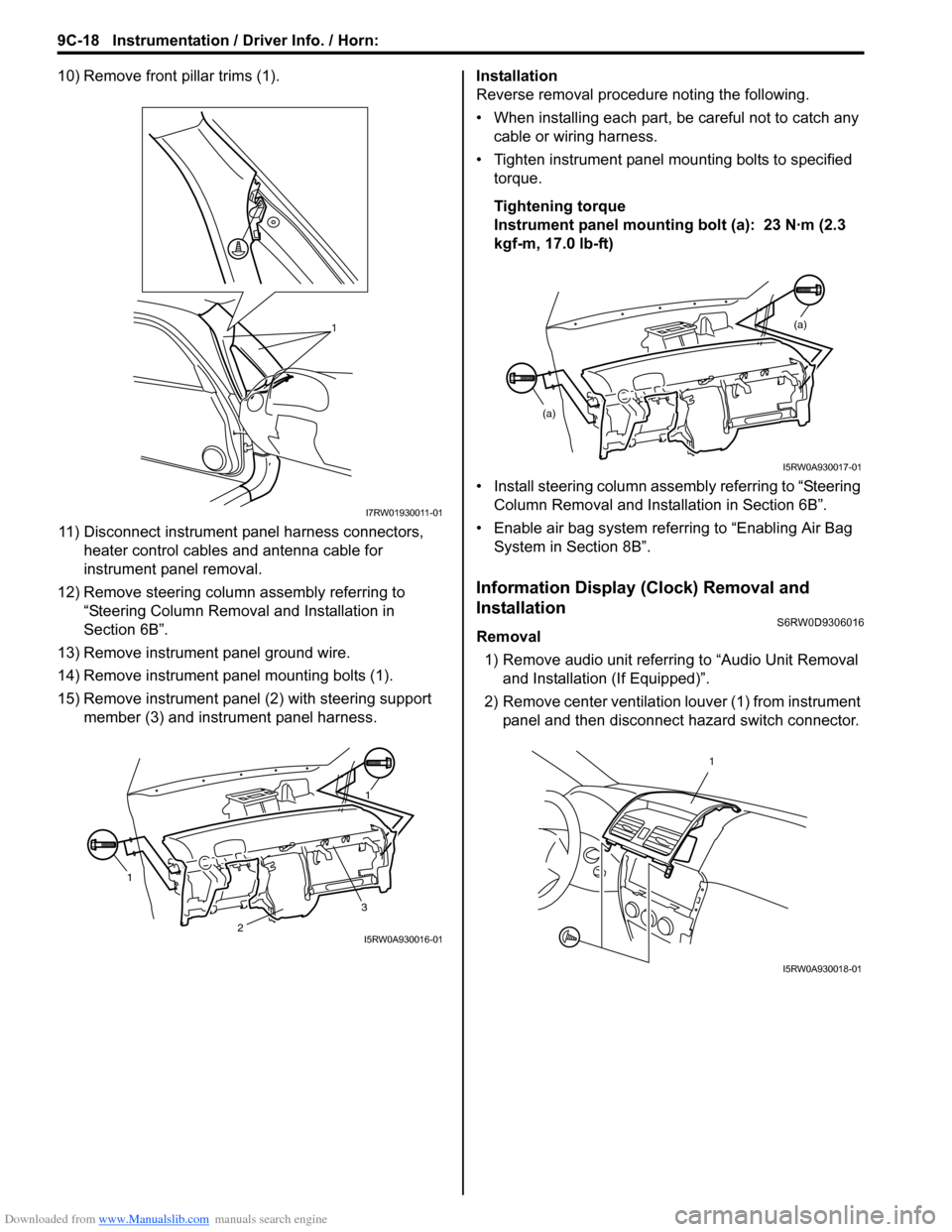
10) Remove front pillar trims (1).
11) Disconnect instrument panel harness connectors,
heater control cables and antenna cable for
instrument panel removal.
12) Remove steering column assembly referring to
“Steering Column Removal and Installation in
Section 6B”.
13) Remove instrument panel ground wire.
14) Remove instrument panel mounting bolts (1).
15) Remove instrument panel (2) with steering support
member (3) and instrument panel harness.Installation
Reverse removal procedure noting the following.
• When installing each part, be careful not to catch any
cable or wiring harness.
• Tighten instrument panel mounting bolts to specified
torque.
Tightening torque
Instrument panel mounting bolt (a): 23 N·m (2.3
kgf-m, 17.0 lb-ft)
• Install steering column assembly referring to “Steering
Column Removal and Installation in Section 6B”.
• Enable air bag system referring to “Enabling Air Bag
System in Section 8B”.
Information Display (Clock) Removal and
Installation
S6RW0D9306016
Removal
1) Remove audio unit referring to “Audio Unit Removal
and Installation (If Equipped)”.
2) Remove center ventilation louver (1) from instrument
panel and then disconnect hazard switch connector.
1
I7RW01930011-01
11
3
2I5RW0A930016-01
(a)
(a)
I5RW0A930017-01
1
I5RW0A930018-01
Page 1374 of 1556
Downloaded from www.Manualslib.com manuals search engine 9C-22 Instrumentation / Driver Info. / Horn:
Remote Audio Control Switch Inspection (If
Equipped)
S6RW0D9306025
1) Remove driver air bag (inflator) module referring to
“Driver Air Bag (Inflator) Module Removal and
Installation in Section 8B”.
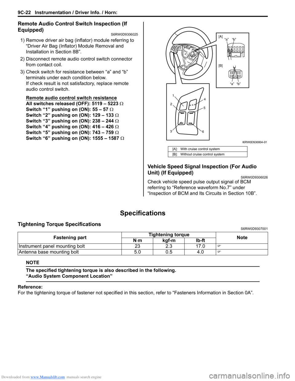
2) Disconnect remote audio control switch connector
from contact coil.
3) Check switch for resistance between “a” and “b”
terminals under each condition below.
If check result is not satisfactory, replace remote
audio control switch.
Remote audio control switch resistance
All switches released (OFF): 5119 – 5223 Ω
Switch “1” pushing on (ON): 55 – 57 Ω
Switch “2” pushing on (ON): 129 – 133 Ω
Switch “3” pushing on (ON): 238 – 244 Ω
Switch “4” pushing on (ON): 416 – 426 Ω
Switch “5” pushing on (ON): 743 – 759 Ω
Switch “6” pushing on (ON): 1555 – 1587 Ω
Vehicle Speed Signal Inspection (For Audio
Unit) (If Equipped)
S6RW0D9306026
Check vehicle speed pulse output signal of BCM
referring to “Reference waveform No.7” under
“Inspection of BCM and Its Circuits in Section 10B”.
Specifications
Tightening Torque SpecificationsS6RW0D9307001
NOTE
The specified tightening torque is also described in the following.
“Audio System Component Location”
Reference:
For the tightening torque of fastener not specified in this section, refer to “Fasteners Information in Section 0A”.
[A]: With cruise control system
[B]: Without cruise control system
1
2
34
5
6
“b” “a”
“b” “a” [A]
[B]
I6RW0D930004-01
Fastening partTightening torque
Note
N⋅mkgf-mlb-ft
Instrument panel mounting bolt 23 2.3 17.0�)
Antenna base mounting bolt 5.0 0.5 4.0�)
Page 1375 of 1556
Downloaded from www.Manualslib.com manuals search engine Wipers / Washers: 9D-1
Body, Cab and Accessories
Wipers / Washers
Diagnostic Information and Procedures
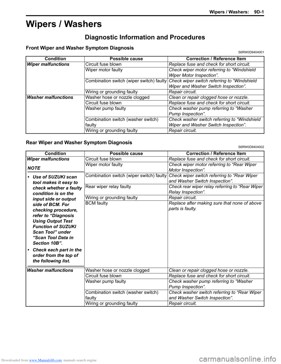
Front Wiper and Washer Symptom DiagnosisS6RW0D9404001
Rear Wiper and Washer Symptom DiagnosisS6RW0D9404002
Condition Possible cause Correction / Reference Item
Wiper malfunctionsCircuit fuse blownReplace fuse and check for short circuit.
Wiper motor faultyCheck wiper motor referring to “Windshield
Wiper Motor Inspection”.
Combination switch (wiper switch) faultyCheck wiper switch referring to “Windshield
Wiper and Washer Switch Inspection”.
Wiring or grounding faultyRepair circuit.
Washer malfunctionsWasher hose or nozzle cloggedClean or repair clogged hose or nozzle.
Circuit fuse blownReplace fuse and check for short circuit.
Washer pump faultyCheck washer pump referring to “Washer
Pump Inspection”.
Combination switch (washer switch)
faultyCheck washer switch referring to “Windshield
Wiper and Washer Switch Inspection”.
Wiring or grounding faultyRepair circuit.
Condition Possible cause Correction / Reference Item
Wiper malfunctions
NOTE
• Use of SUZUKI scan
tool makes it easy to
check whether a faulty
condition is on the
input side or output
side of BCM. For
checking procedure,
refer to “Diagnosis
Using Output Test
Function of SUZUKI
Scan Tool” under
“Scan Tool Data in
Section 10B”.
• Check each part in the
order from the top of
the following list.
Circuit fuse blownReplace fuse and check for short circuit.
Wiper motor faultyCheck wiper motor referring to “Rear Wiper
Motor Inspection”.
Combination switch (wiper switch) faultyCheck wiper switch referring to “Rear Wiper
and Washer Switch Inspection”.
Rear wiper relay faultyCheck rear wiper relay referring to “Rear Wiper
Relay Inspection”.
Wiring or grounding faultyRepair circuit.
BCM faultyReplace after making sure that none of above
parts is faulty.
Washer malfunctionsWasher hose or nozzle cloggedClean or repair clogged hose or nozzle.
Circuit fuse blownReplace fuse and check for short circuit.
Washer pump faultyCheck washer pump referring to “Washer
Pump Inspection”.
Combination switch (washer switch)
faultyCheck washer switch referring to “Rear Wiper
and Washer Switch Inspection”.
Wiring or grounding faultyRepair circuit.
Page 1376 of 1556
![SUZUKI SX4 2006 1.G Service Workshop Manual Downloaded from www.Manualslib.com manuals search engine 9D-2 Wipers / Washers:
Repair Instructions
Wipers and Washers ComponentsS6RW0D9406001
115
6
(b)
(a) 1 1
(b)
2
1314
14[A]
14
1215
(c)
(b)
(a)
3 SUZUKI SX4 2006 1.G Service Workshop Manual Downloaded from www.Manualslib.com manuals search engine 9D-2 Wipers / Washers:
Repair Instructions
Wipers and Washers ComponentsS6RW0D9406001
115
6
(b)
(a) 1 1
(b)
2
1314
14[A]
14
1215
(c)
(b)
(a)
3](/manual-img/20/7612/w960_7612-1375.png)
Downloaded from www.Manualslib.com manuals search engine 9D-2 Wipers / Washers:
Repair Instructions
Wipers and Washers ComponentsS6RW0D9406001
115
6
(b)
(a) 1 1
(b)
2
1314
14[A]
14
1215
(c)
(b)
(a)
32
4
710
10
10 11118
16
9
16
I7RW01940001-03
1. Windshield wiper blade 8. Washer pump for rear washer 15. Windshield wiper bolt
:Tighten bolts in specified order.
2. Windshield wiper arm 9. Washer tank 16. Washer tank bolt
3. Windshield wiper motor 10. Washer hose[A]: Junction block viewed from relay
side
4. Windshield wiper link 11. Washer nozzle : 18 N⋅m (1.8 kgf-m, 13.0 lb-ft)
Page 1388 of 1556
Downloaded from www.Manualslib.com manuals search engine 9E-3 Glass / Windows / Mirrors:
Diagnostic Information and Procedures
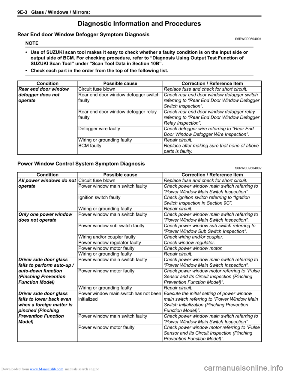
Rear End door Window Defogger Symptom DiagnosisS6RW0D9504001
NOTE
• Use of SUZUKI scan tool makes it easy to check whether a faulty condition is on the input side or
output side of BCM. For checking procedure, refer to “Diagnosis Using Output Test Function of
SUZUKI Scan Tool” under “Scan Tool Data in Section 10B”.
• Check each part in the order from the top of the following list.
Power Window Control System Symptom DiagnosisS6RW0D9504002
Condition Possible cause Correction / Reference Item
Rear end door window
defogger does not
operateCircuit fuse blownReplace fuse and check for short circuit.
Rear end door window defogger switch
faultyCheck rear end door window defogger switch
referring to “Rear End Door Window Defogger
Switch Inspection”.
Rear end door window defogger relay
faultyCheck rear end door window defogger relay
referring to “Rear End Door Window Defogger
Relay Inspection”.
Defogger wire faultyCheck defogger wire referring to “Rear End
Door Window Defogger Wire Inspection”.
Wiring or grounding faultyRepair circuit.
BCM faultyReplace after making sure that none of above
parts is faulty.
Condition Possible cause Correction / Reference Item
All power windows do not
operateCircuit fuse blownReplace fuse and check for short circuit.
Power window main switch faultyCheck power window main switch referring to
“Power Window Main Switch Inspection”.
Ignition switch faultyCheck ignition switch referring to “Ignition
Switch Inspection in Section 9C”.
Wiring or grounding faultyRepair circuit.
Only one power window
does not operatePower window main switch faultyCheck power window main switch referring to
“Power Window Main Switch Inspection”.
Power window sub switch faultyCheck power window sub switch referring to
“Power Window Sub Switch Inspection”.
Wiring and/or coupler faultyCheck wiring and/or coupler.
Power window regulator faultyCheck window regulator.
Power window motor faultyCheck power window motor.
Wiring or grounding faultyRepair circuit.
Driver side door glass
fails to perform auto-up /
auto-down function
(Pinching Prevention
Function Model)Power window main switch faultyCheck power window main switch referring to
“Power Window Main Switch Inspection”.
Power window motor faultyCheck power window motor referring to “Pulse
Sensor and Its Circuit Inspection (Pinching
Prevention Function Model)”.
Wiring or grounding faultyRepair circuit.
Driver side door glass
fails to lower back even
when a foreign matter is
pinched (Pinching
Prevention Function
Model)Power window main switch has not been
initializedExecute the initial setting of power window
main switch referring to “Power Window Main
Switch Initialization (Pinching Prevention
Function Model)”.
Power window main switch faultyCheck power window main switch referring to
“Power Window Main Switch Inspection”.
Power window motor faultyCheck power window motor referring to “Pulse
Sensor and Its Circuit Inspection (Pinching
Prevention Function Model)”.