2006 SUZUKI SX4 radio
[x] Cancel search: radioPage 15 of 1556
Downloaded from www.Manualslib.com manuals search engine Precautions: 00-8
Precautions for Installing Mobile
Communication Equipment
S6RW0D0000005
When installing mobile communication equipment such
as CB (Citizens-Band)-radio or cellular-telephone, be
sure to observe the following precautions.
Failure to follow cautions may adversely affect electronic
control system.
• Keep the antenna as far away as possible from the
vehicle’s electronic control unit.
• Keep the antenna feeder more than 20 cm (7.9 in.)
away from electronic control unit and its wire
harnesses.
• Do not run the antenna feeder parallel with other wire
harnesses.
• Confirm that the antenna and feeder are correctly
adjusted.
Precaution for CAN Communication SystemS6RW0D0000006
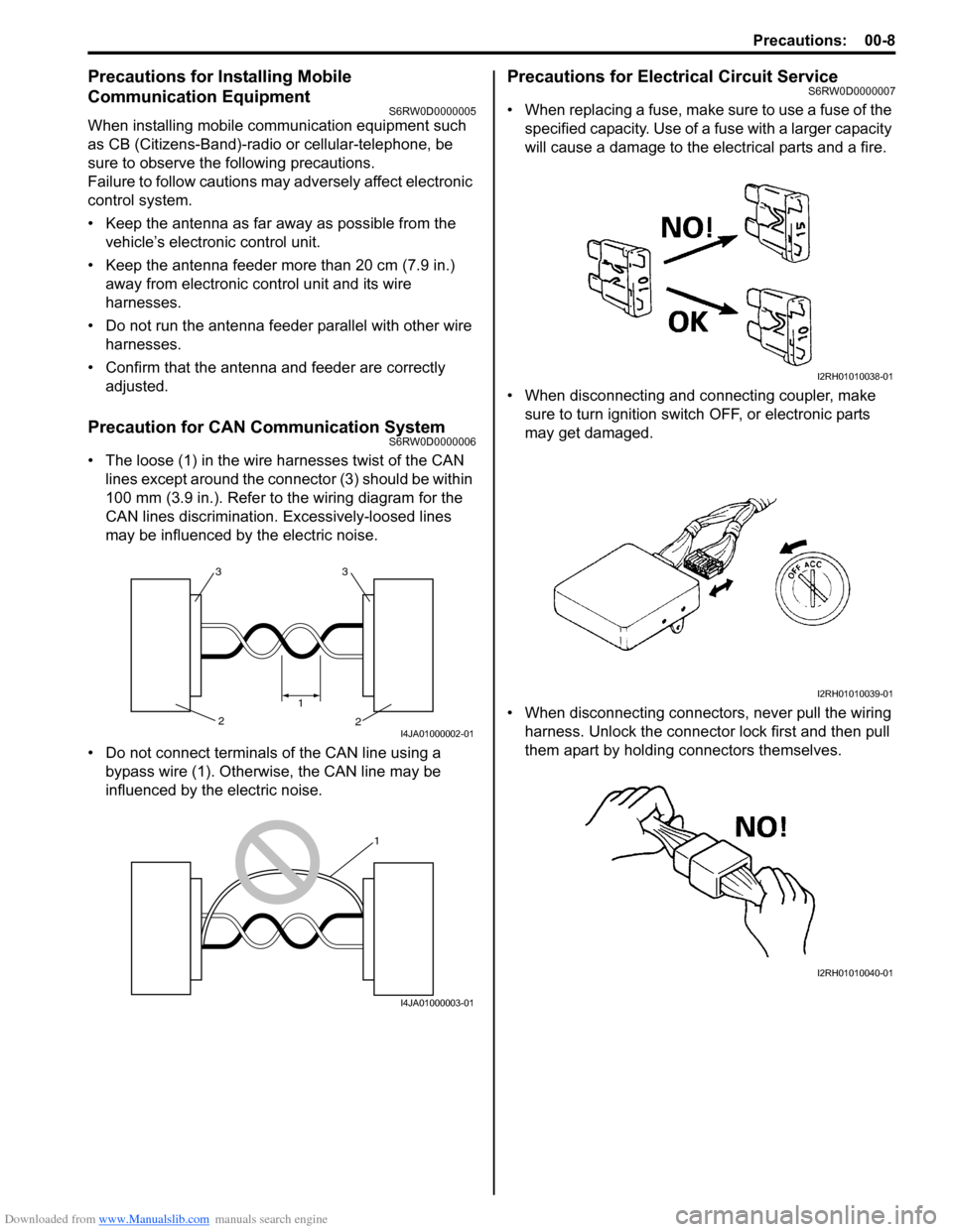
• The loose (1) in the wire harnesses twist of the CAN
lines except around the connector (3) should be within
100 mm (3.9 in.). Refer to the wiring diagram for the
CAN lines discrimination. Excessively-loosed lines
may be influenced by the electric noise.
• Do not connect terminals of the CAN line using a
bypass wire (1). Otherwise, the CAN line may be
influenced by the electric noise.
Precautions for Electrical Circuit ServiceS6RW0D0000007
• When replacing a fuse, make sure to use a fuse of the
specified capacity. Use of a fuse with a larger capacity
will cause a damage to the electrical parts and a fire.
• When disconnecting and connecting coupler, make
sure to turn ignition switch OFF, or electronic parts
may get damaged.
• When disconnecting connectors, never pull the wiring
harness. Unlock the connector lock first and then pull
them apart by holding connectors themselves.
33
2 2
1
I4JA01000002-01
1
I4JA01000003-01
I2RH01010038-01
I2RH01010039-01
I2RH01010040-01
Page 1357 of 1556
Downloaded from www.Manualslib.com manuals search engine Instrumentation / Driver Info. / Horn: 9C-5
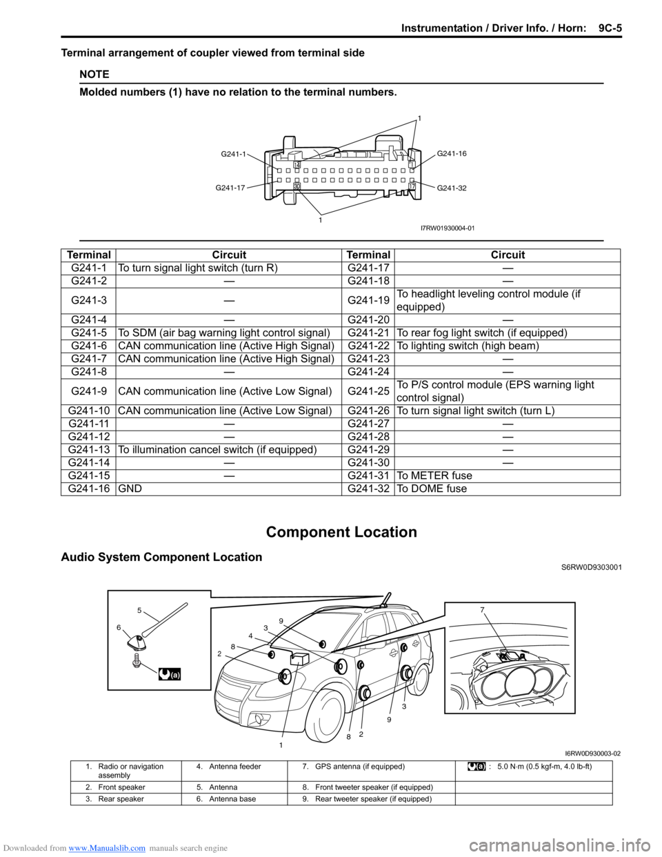
Terminal arrangement of coupler viewed from terminal side
NOTE
Molded numbers (1) have no relation to the terminal numbers.
Component Location
Audio System Component LocationS6RW0D9303001
Terminal Circuit Terminal Circuit
G241-1 To turn signal light switch (turn R) G241-17 —
G241-2 — G241-18 —
G241-3 — G241-19To headlight leveling control module (if
equipped)
G241-4 — G241-20 —
G241-5 To SDM (air bag warning light control signal) G241-21 To rear fog light switch (if equipped)
G241-6 CAN communication line (Active High Signal) G241-22 To lighting switch (high beam)
G241-7 CAN communication line (Active High Signal) G241-23 —
G241-8 — G241-24 —
G241-9 CAN communication line (Active Low Signal) G241-25To P/S control module (EPS warning light
control signal)
G241-10 CAN communication line (Active Low Signal) G241-26 To turn signal light switch (turn L)
G241-11 — G241-27 —
G241-12 — G241-28 —
G241-13 To illumination cancel switch (if equipped) G241-29 —
G241-14 — G241-30 —
G241-15 — G241-31 To METER fuse
G241-16 GND G241-32 To DOME fuse
G241-1G241-16
G241-32 G241-17
11I7RW01930004-01
3
2
3
2
1
4
8
8
9
96
5
(a)
7
I6RW0D930003-02
1. Radio or navigation
assembly4. Antenna feeder 7. GPS antenna (if equipped) : 5.0 N⋅m (0.5 kgf-m, 4.0 lb-ft)
2. Front speaker 5. Antenna 8. Front tweeter speaker (if equipped)
3. Rear speaker 6. Antenna base 9. Rear tweeter speaker (if equipped)
Page 1364 of 1556
Downloaded from www.Manualslib.com manuals search engine 9C-12 Instrumentation / Driver Info. / Horn:
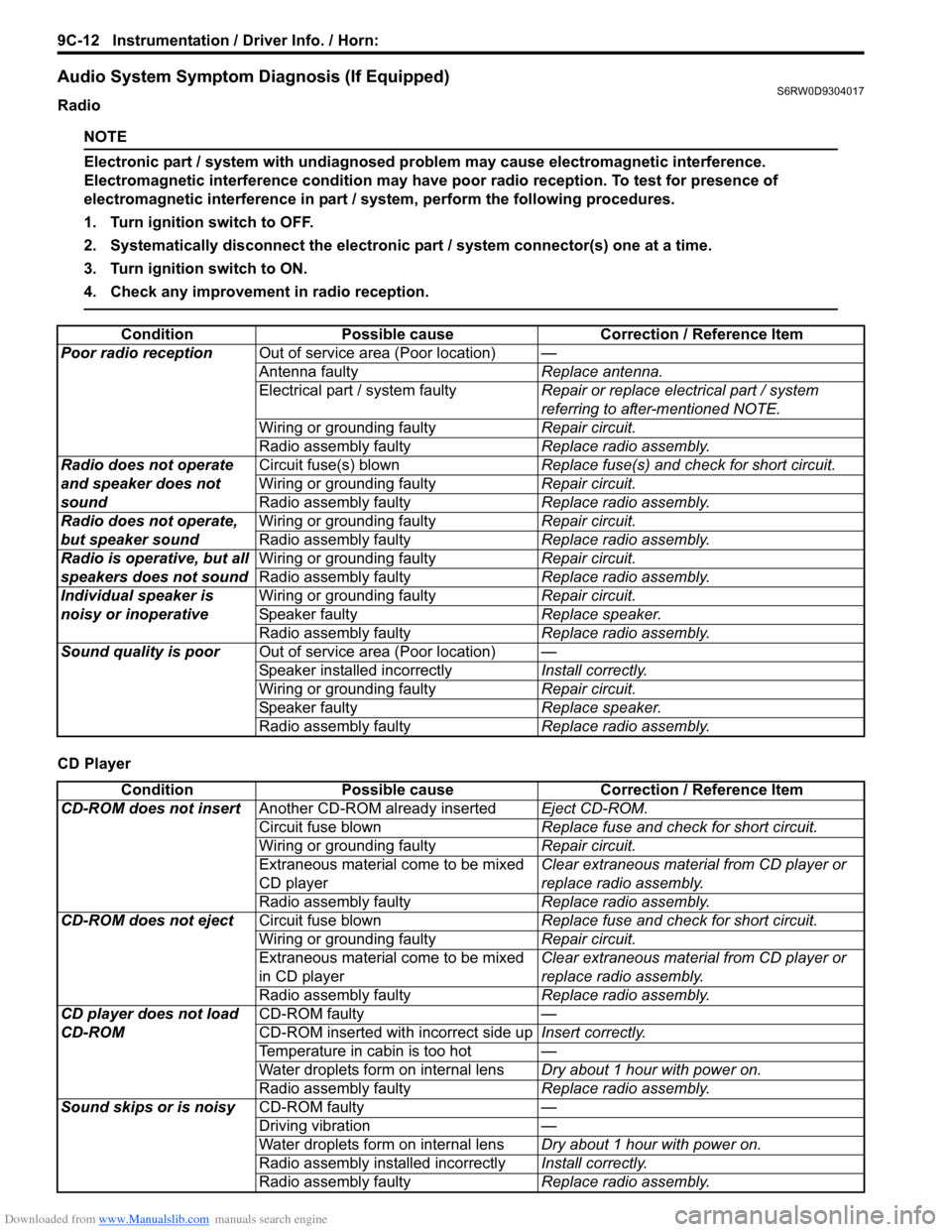
Audio System Symptom Diagnosis (If Equipped)S6RW0D9304017
Radio
NOTE
Electronic part / system with undiagnosed problem may cause electromagnetic interference.
Electromagnetic interference condition may have poor radio reception. To test for presence of
electromagnetic interference in part / system, perform the following procedures.
1. Turn ignition switch to OFF.
2. Systematically disconnect the electronic part / system connector(s) one at a time.
3. Turn ignition switch to ON.
4. Check any improvement in radio reception.
CD PlayerCondition Possible cause Correction / Reference Item
Poor radio receptionOut of service area (Poor location)—
Antenna faultyReplace antenna.
Electrical part / system faultyRepair or replace electrical part / system
referring to after-mentioned NOTE.
Wiring or grounding faultyRepair circuit.
Radio assembly faultyReplace radio assembly.
Radio does not operate
and speaker does not
soundCircuit fuse(s) blownReplace fuse(s) and check for short circuit.
Wiring or grounding faultyRepair circuit.
Radio assembly faultyReplace radio assembly.
Radio does not operate,
but speaker soundWiring or grounding faultyRepair circuit.
Radio assembly faultyReplace radio assembly.
Radio is operative, but all
speakers does not soundWiring or grounding faultyRepair circuit.
Radio assembly faultyReplace radio assembly.
Individual speaker is
noisy or inoperativeWiring or grounding faultyRepair circuit.
Speaker faultyReplace speaker.
Radio assembly faultyReplace radio assembly.
Sound quality is poorOut of service area (Poor location)—
Speaker installed incorrectlyInstall correctly.
Wiring or grounding faultyRepair circuit.
Speaker faultyReplace speaker.
Radio assembly faultyReplace radio assembly.
Condition Possible cause Correction / Reference Item
CD-ROM does not insertAnother CD-ROM already insertedEject CD-ROM.
Circuit fuse blownReplace fuse and check for short circuit.
Wiring or grounding faultyRepair circuit.
Extraneous material come to be mixed
CD playerClear extraneous material from CD player or
replace radio assembly.
Radio assembly faultyReplace radio assembly.
CD-ROM does not ejectCircuit fuse blownReplace fuse and check for short circuit.
Wiring or grounding faultyRepair circuit.
Extraneous material come to be mixed
in CD playerClear extraneous material from CD player or
replace radio assembly.
Radio assembly faultyReplace radio assembly.
CD player does not load
CD-ROMCD-ROM faulty—
CD-ROM inserted with incorrect side upInsert correctly.
Temperature in cabin is too hot—
Water droplets form on internal lensDry about 1 hour with power on.
Radio assembly faultyReplace radio assembly.
Sound skips or is noisyCD-ROM faulty—
Driving vibration—
Water droplets form on internal lensDry about 1 hour with power on.
Radio assembly installed incorrectlyInstall correctly.
Radio assembly faultyReplace radio assembly.
Page 1365 of 1556
Downloaded from www.Manualslib.com manuals search engine Instrumentation / Driver Info. / Horn: 9C-13
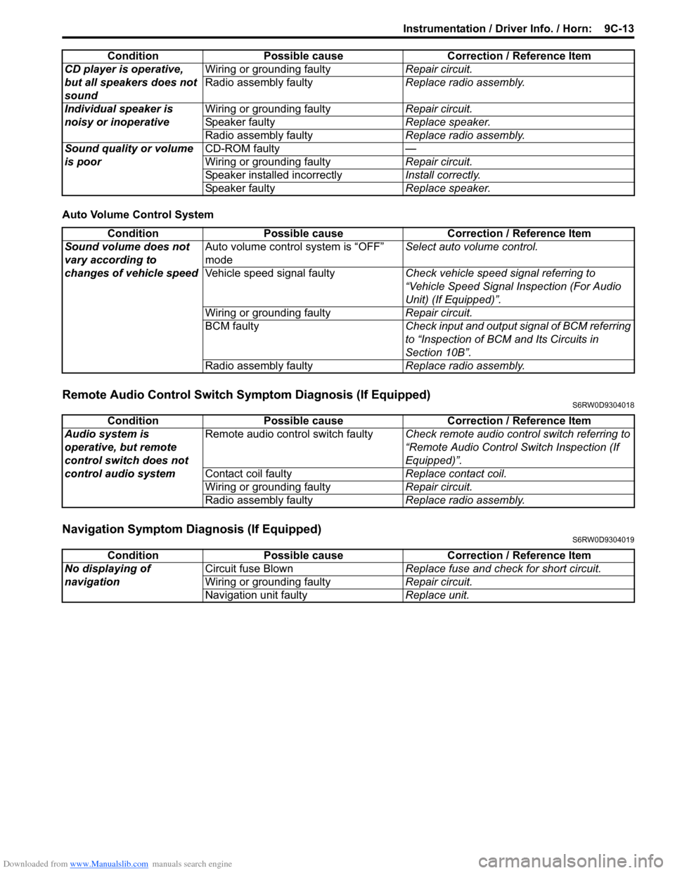
Auto Volume Control System
Remote Audio Control Switch Symptom Diagnosis (If Equipped)S6RW0D9304018
Navigation Symptom Diagnosis (If Equipped)S6RW0D9304019
CD player is operative,
but all speakers does not
soundWiring or grounding faultyRepair circuit.
Radio assembly faultyReplace radio assembly.
Individual speaker is
noisy or inoperativeWiring or grounding faultyRepair circuit.
Speaker faultyReplace speaker.
Radio assembly faultyReplace radio assembly.
Sound quality or volume
is poorCD-ROM faulty—
Wiring or grounding faultyRepair circuit.
Speaker installed incorrectlyInstall correctly.
Speaker faultyReplace speaker. Condition Possible cause Correction / Reference Item
Condition Possible cause Correction / Reference Item
Sound volume does not
vary according to
changes of vehicle speedAuto volume control system is “OFF”
modeSelect auto volume control.
Vehicle speed signal faultyCheck vehicle speed signal referring to
“Vehicle Speed Signal Inspection (For Audio
Unit) (If Equipped)”.
Wiring or grounding faultyRepair circuit.
BCM faultyCheck input and output signal of BCM referring
to “Inspection of BCM and Its Circuits in
Section 10B”.
Radio assembly faultyReplace radio assembly.
Condition Possible cause Correction / Reference Item
Audio system is
operative, but remote
control switch does not
control audio systemRemote audio control switch faultyCheck remote audio control switch referring to
“Remote Audio Control Switch Inspection (If
Equipped)”.
Contact coil faultyReplace contact coil.
Wiring or grounding faultyRepair circuit.
Radio assembly faultyReplace radio assembly.
Condition Possible cause Correction / Reference Item
No displaying of
navigationCircuit fuse BlownReplace fuse and check for short circuit.
Wiring or grounding faultyRepair circuit.
Navigation unit faultyReplace unit.
Page 1504 of 1556
Downloaded from www.Manualslib.com manuals search engine 10C-2 Immobilizer Control System:
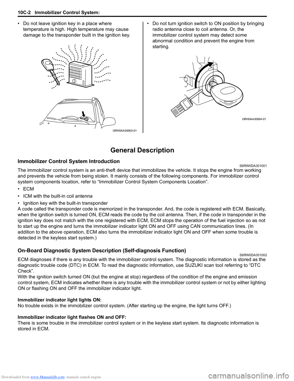
• Do not leave ignition key in a place where
temperature is high. High temperature may cause
damage to the transponder built in the ignition key.• Do not turn ignition switch to ON position by bringing
radio antenna close to coil antenna. Or, the
immobilizer control system may detect some
abnormal condition and prevent the engine from
starting.
General Description
Immobilizer Control System IntroductionS6RW0DA301001
The immobilizer control system is an anti-theft device that immobilizes the vehicle. It stops the engine from working
and prevents the vehicle from being stolen. It mainly consists of the following components. For immobilizer control
system components location, refer to “Immobilizer Control System Components Location”.
•ECM
• ICM with the built-in coil antenna
• Ignition key with the built-in transponder
A code called the transponder code is memorized in the transponder. And, the code is registered with ECM. Basically,
when the ignition switch is turned ON, ECM reads the code by the coil antenna. Then, if the code in transponder in the
ignition key does not match with the one registered with ECM, ECM stops the operation of the fuel injection so as not
to start up the engine and turns the immobilizer indicator light ON and OFF using CAN communication lines. (In
addition to the above operation, ECM also turns the immobilizer indicator light ON and OFF when some trouble is
detected in the keyless start system.)
On-Board Diagnostic System Description (Self-diagnosis Function)S6RW0DA301002
ECM diagnoses if there is any trouble with the immobilizer control system. The diagnostic information is stored as the
diagnostic trouble code (DTC) in ECM. To read the diagnostic information, use SUZUKI scan tool referring to “DTC
Check”.
With the ignition switch turned ON (but the engine at stop) regardless of the condition of the engine and emission
control system, ECM indicates whether there is any trouble with the immobilizer control system or not by either lighting
ON or flashing ON and OFF the immobilizer indicator light.
Immobilizer indicator light lights ON:
No trouble exists in the immobilizer control system. (After starting up the engine, the light turns OFF.)
Immobilizer indicator light flashes ON and OFF:
There is some trouble in the immobilizer control system or in the keyless start system. Its diagnostic information is
stored in ECM.
I3RH0AA30003-01
I3RH0AA30004-01
Page 1526 of 1556
Downloaded from www.Manualslib.com manuals search engine 10E-4 Keyless Start System:
Door Lock Function of Keyless Start SystemS6RW0DA501004
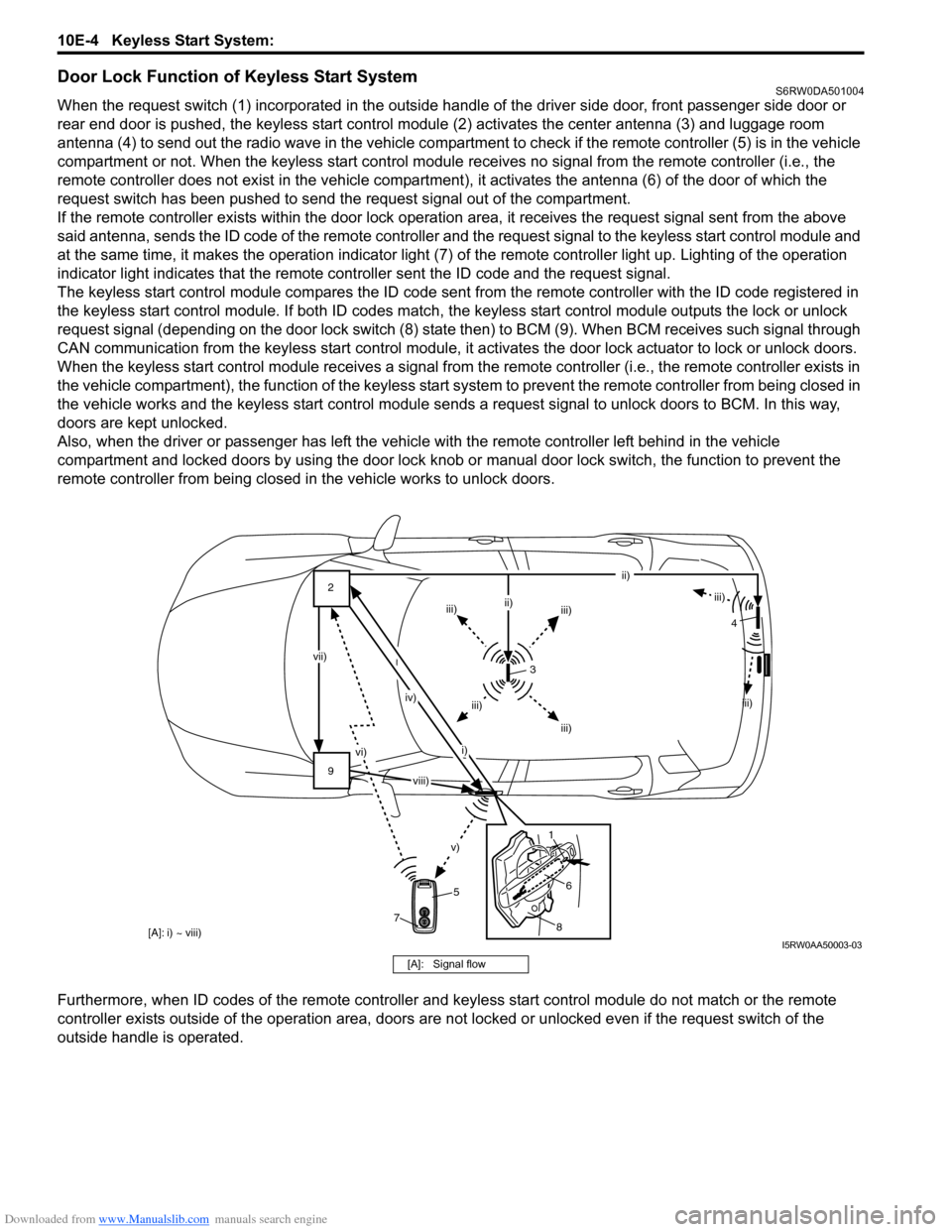
When the request switch (1) incorporated in the outside handle of the driver side door, front passenger side door or
rear end door is pushed, the keyless start control module (2) activates the center antenna (3) and luggage room
antenna (4) to send out the radio wave in the vehicle compartment to check if the remote controller (5) is in the vehicle
compartment or not. When the keyless start control module receives no signal from the remote controller (i.e., the
remote controller does not exist in the vehicle compartment), it activates the antenna (6) of the door of which the
request switch has been pushed to send the request signal out of the compartment.
If the remote controller exists within the door lock operation area, it receives the request signal sent from the above
said antenna, sends the ID code of the remote controller and the request signal to the keyless start control module and
at the same time, it makes the operation indicator light (7) of the remote controller light up. Lighting of the operation
indicator light indicates that the remote controller sent the ID code and the request signal.
The keyless start control module compares the ID code sent from the remote controller with the ID code registered in
the keyless start control module. If both ID codes match, the keyless start control module outputs the lock or unlock
request signal (depending on the door lock switch (8) state then) to BCM (9). When BCM receives such signal through
CAN communication from the keyless start control module, it activates the door lock actuator to lock or unlock doors.
When the keyless start control module receives a signal from the remote controller (i.e., the remote controller exists in
the vehicle compartment), the function of the keyless start system to prevent the remote controller from being closed in
the vehicle works and the keyless start control module sends a request signal to unlock doors to BCM. In this way,
doors are kept unlocked.
Also, when the driver or passenger has left the vehicle with the remote controller left behind in the vehicle
compartment and locked doors by using the door lock knob or manual door lock switch, the function to prevent the
remote controller from being closed in the vehicle works to unlock doors.
Furthermore, when ID codes of the remote controller and keyless start control module do not match or the remote
controller exists outside of the operation area, doors are not locked or unlocked even if the request switch of the
outside handle is operated.
[A]: i) ~ viii)
9 2
vi)
v)
vii)
iv)
i)ii)
iii)
iii)iii) ii)
iii)
iii) iii)
3
5
8
6 14
7
viii)
I5RW0AA50003-03
[A]: Signal flow
Page 1527 of 1556
Downloaded from www.Manualslib.com manuals search engine Keyless Start System: 10E-5
Operation Area of Remote ControllerS6RW0DA501005
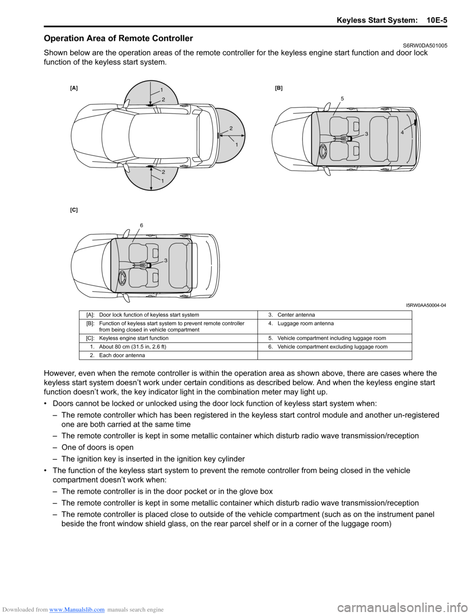
Shown below are the operation areas of the remote controller for the keyless engine start function and door lock
function of the keyless start system.
However, even when the remote controller is within the operation area as shown above, there are cases where the
keyless start system doesn’t work under certain conditions as described below. And when the keyless engine start
function doesn’t work, the key indicator light in the combination meter may light up.
• Doors cannot be locked or unlocked using the door lock function of keyless start system when:
– The remote controller which has been registered in the keyless start control module and another un-registered
one are both carried at the same time
– The remote controller is kept in some metallic container which disturb radio wave transmission/reception
– One of doors is open
– The ignition key is inserted in the ignition key cylinder
• The function of the keyless start system to prevent the remote controller from being closed in the vehicle
compartment doesn’t work when:
– The remote controller is in the door pocket or in the glove box
– The remote controller is kept in some metallic container which disturb radio wave transmission/reception
– The remote controller is placed close to outside of the vehicle compartment (such as on the instrument panel
beside the front window shield glass, on the rear parcel shelf or in a corner of the luggage room)
[A][B]
[C]1
1
1
2
2
25
34
6
3
I5RW0AA50004-04
[A]: Door lock function of keyless start system 3. Center antenna
[B]: Function of keyless start system to prevent remote controller
from being closed in vehicle compartment4. Luggage room antenna
[C]: Keyless engine start function 5. Vehicle compartment including luggage room
1. About 80 cm (31.5 in, 2.6 ft) 6. Vehicle compartment excluding luggage room
2. Each door antenna
Page 1528 of 1556
Downloaded from www.Manualslib.com manuals search engine 10E-6 Keyless Start System:
• The ignition knob switch cannot be turned using the keyless engine start function fails to turn:
– The remote controller which has been registered in the keyless start control module and another un-registered
one are both carried at the same time
– The remote controller is kept in some metallic container which disturbs radio wave transmission/reception
– The ignition knob switch has been pushed for 5 seconds or longer
– The remote controller is placed close to outside of the vehicle compartment (such as on the instrument panel
beside the front window shield glass, on the rear parcel shelf or in a corner of the luggage room)
Alarm FunctionS6RW0DA501006
Under conditions as described in the table below, the keyless start control module makes the key indicator light flash in
red and the buzzer sound to call the driver’s attention.
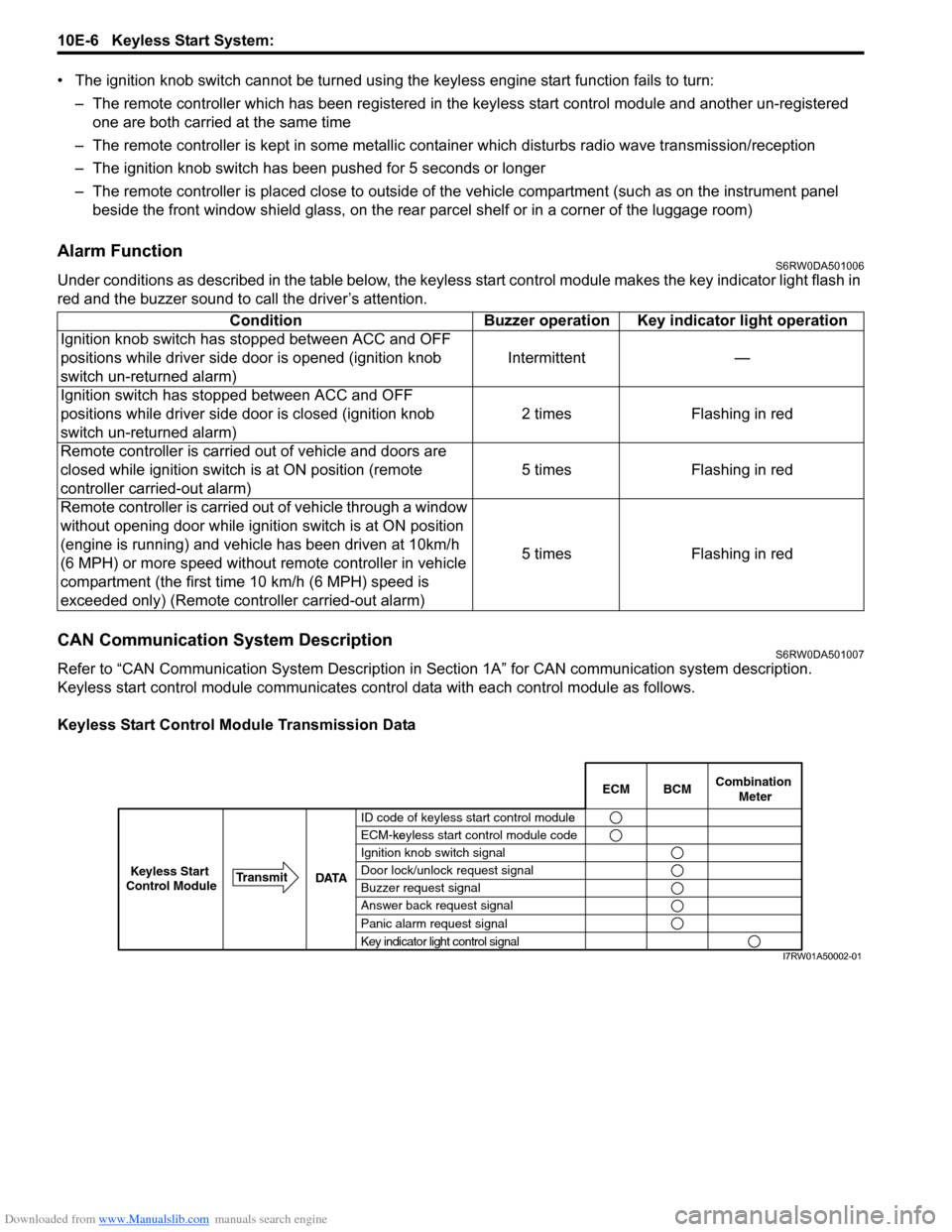
CAN Communication System DescriptionS6RW0DA501007
Refer to “CAN Communication System Description in Section 1A” for CAN communication system description.
Keyless start control module communicates control data with each control module as follows.
Keyless Start Control Module Transmission DataCondition Buzzer operation Key indicator light operation
Ignition knob switch has stopped between ACC and OFF
positions while driver side door is opened (ignition knob
switch un-returned alarm)Intermittent —
Ignition switch has stopped between ACC and OFF
positions while driver side door is closed (ignition knob
switch un-returned alarm)2 times Flashing in red
Remote controller is carried out of vehicle and doors are
closed while ignition switch is at ON position (remote
controller carried-out alarm)5 times Flashing in red
Remote controller is carried out of vehicle through a window
without opening door while ignition switch is at ON position
(engine is running) and vehicle has been driven at 10km/h
(6 MPH) or more speed without remote controller in vehicle
compartment (the first time 10 km/h (6 MPH) speed is
exceeded only) (Remote controller carried-out alarm)5 times Flashing in red
BCM ECMCombination
Meter
ID code of keyless start control modulee
ECM-keyless start control module codeke
Ignition knob switch signal
Door lock/unlock request signal
Buzzer request signal
Answer back request signal
Panic alarm request signal
Key indicator light control signal DATA Transmit
Keyless Start
Control Module
I7RW01A50002-01