Page 1417 of 1556

Downloaded from www.Manualslib.com manuals search engine Security and Locks: 9F-6
Repair Instructions
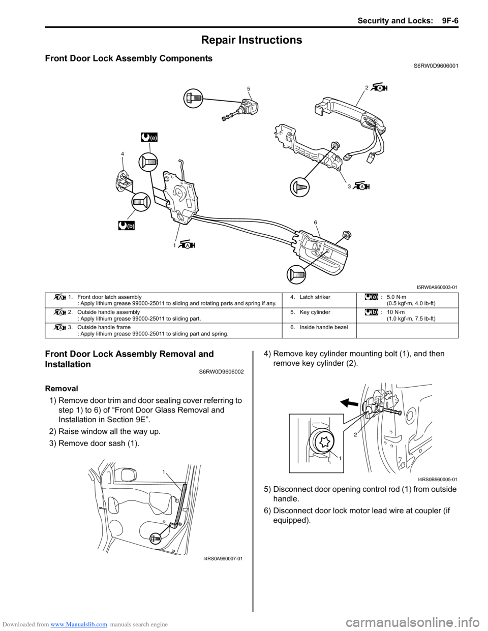
Front Door Lock Assembly ComponentsS6RW0D9606001
Front Door Lock Assembly Removal and
Installation
S6RW0D9606002
Removal
1) Remove door trim and door sealing cover referring to
step 1) to 6) of “Front Door Glass Removal and
Installation in Section 9E”.
2) Raise window all the way up.
3) Remove door sash (1).4) Remove key cylinder mounting bolt (1), and then
remove key cylinder (2).
5) Disconnect door opening control rod (1) from outside
handle.
6) Disconnect door lock motor lead wire at coupler (if
equipped).
(a)
(b)
5
3
6
1 4
2
I5RW0A960003-01
1. Front door latch assembly
: Apply lithium grease 99000-25011 to sliding and rotating parts and spring if any.4. Latch striker : 5.0 N⋅m
(0.5 kgf-m, 4.0 lb-ft)
2. Outside handle assembly
: Apply lithium grease 99000-25011 to sliding part.5. Key cylinder : 10 N⋅m
(1.0 kgf-m, 7.5 lb-ft)
3. Outside handle frame
: Apply lithium grease 99000-25011 to sliding part and spring.6. Inside handle bezel
1
I4RS0A960007-01
12
I4RS0B960005-01
Page 1428 of 1556
Downloaded from www.Manualslib.com manuals search engine 9G-1 Seats:
Body, Cab and Accessories
Seats
Diagnostic Information and Procedures
Front Seat Heater Symptom Diagnosis (If Equipped)S6RW0D9704001
Condition Possible cause Correction / Reference Item
Both seat back and
cushion do not become
hot although seat heater
switch is ON positionWiring or grounding faultyRepair.
“SEAT HTR” fuse blownReplace fuse to check for short.
Seat heater switch faultyReplace switch.
Seat heater circuit in seat back and/or
seat cushion faultyReplace heater front back and/or heater front
cushion.
Only seat back does not
become hot although seat
heater switch is ON
positionWiring faultyRepair.
Seat heater circuit in seat back and/or
seat cushion faultyReplace heater front back and/or heater front
cushion.
Only seat cushion does
not become hot although
seat heater switch is ON
positionWiring faultyRepair.
Seat heater circuit in seat cushion faultyReplace heater front cushion.
Page 1429 of 1556
Downloaded from www.Manualslib.com manuals search engine Seats: 9G-2
Repair Instructions
Front Seat ComponentsS6RW0D9706001
3
2
8
7
a
c
4
d
b
1
5
5
4
6
64
a
b
c
d
(b)
(b)
(b)
(b)
(a)
(a)
(a)
(a)
A
A
A
(b)
(c)
BA
A
A
B
A
B
I6RW0C970001-01
1. Seat cushion7. Side air bag module (if equipped)
2. Seat back
: Apply lithium grease 99000-25011 to sliding part of reclining.8. Side air bag harness (if equipped)
3. Headrest: 23 N⋅m (2.3 kgf-m, 17.0 lb-ft)
4. Cover: 35 N⋅m (3.5 kgf-m, 25.5 lb-ft)
5. Seat adjuster
: Apply lithium grease 99000-25011 to seat adjuster inside.: 28 N⋅m (2.8 kgf-m, 20.5 lb-ft) (Seat lifter type)
35 N⋅m (3.5 kgf-m, 25.5 lb-ft) (Non seat lifter type)
6. Knoba, b, c, d: Seat back mounting bolt
Seat mounting bolt
Tightening order: a → b → c → d
Page 1430 of 1556

Downloaded from www.Manualslib.com manuals search engine 9G-3 Seats:
Front Seat Removal and InstallationS6RW0D9706002
Removal
1) Disable air bag system referring to “Disabling Air
Bag System in Section 8B”.
2) Disconnect seat harness coupler and side air bag
coupler, if equipped.
3) Remove 4 mounting bolts to remove seat assembly.
4) Disassemble and repair seat as necessary.
Installation
Reverse removal procedure to install front seat.
• Torque to specifications as shown in “Front Seat
Components”.
• Enable air bag system referring to “Enabling Air Bag
System in Section 8B”.
Front Seat Heater Switch (Driver and Passenger
Side) Inspection (If Equipped)
S6RW0D9706005
1) Confirm that ignition switch is OFF position.
2) Remove console box.
3) Disconnect seat heater switch coupler and remove
seat heater switch.
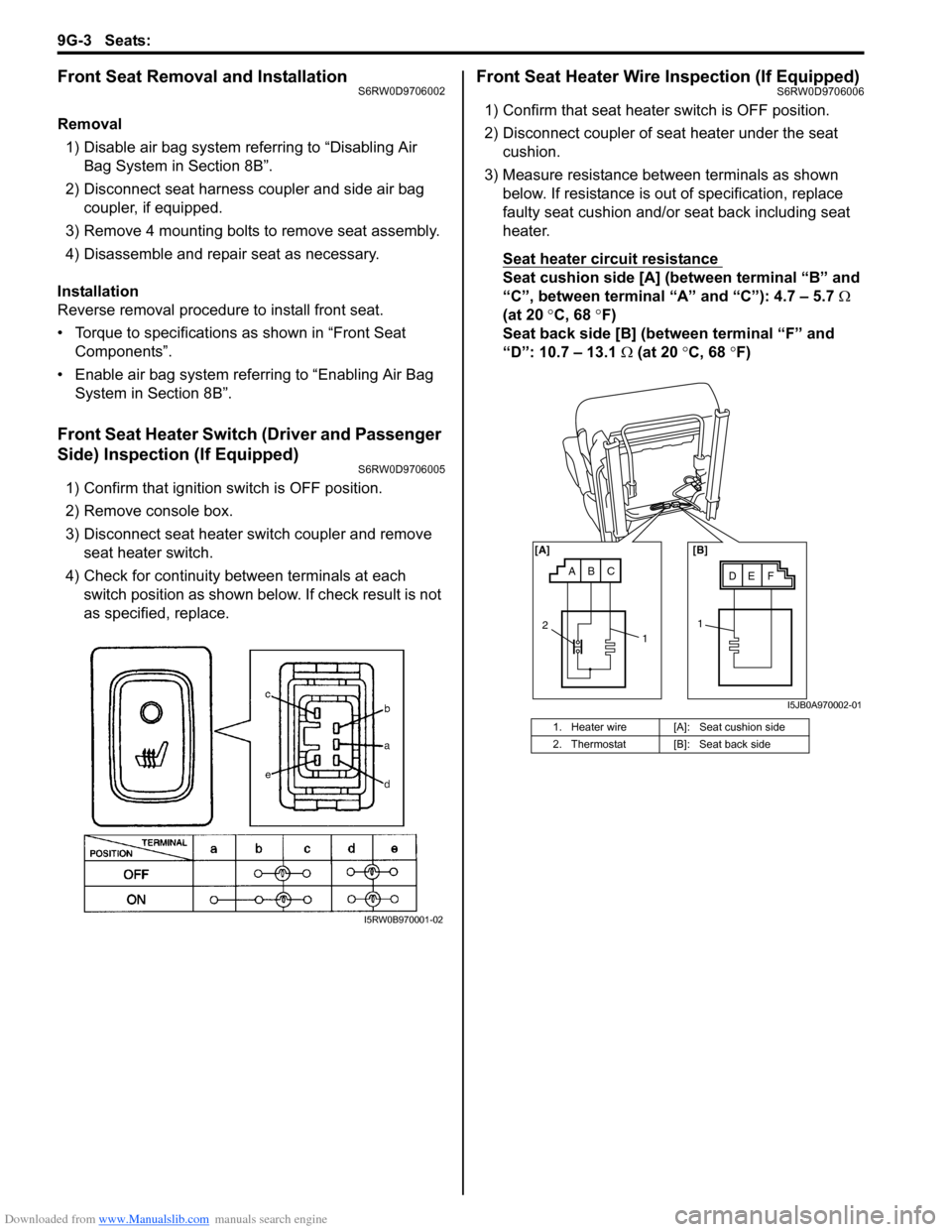
4) Check for continuity between terminals at each
switch position as shown below. If check result is not
as specified, replace.
Front Seat Heater Wire Inspection (If Equipped)S6RW0D9706006
1) Confirm that seat heater switch is OFF position.
2) Disconnect coupler of seat heater under the seat
cushion.
3) Measure resistance between terminals as shown
below. If resistance is out of specification, replace
faulty seat cushion and/or seat back including seat
heater.
Seat heater circuit resistance
Seat cushion side [A] (between terminal “B” and
“C”, between terminal “A” and “C”): 4.7 – 5.7 Ω
(at 20 °C, 68 °F)
Seat back side [B] (between terminal “F” and
“D”: 10.7 – 13.1 Ω (at 20 °C, 68 °F)
I5RW0B970001-02
1. Heater wire [A]: Seat cushion side
2. Thermostat [B]: Seat back side
ABCDE F [A] [B]
11
2
I5JB0A970002-01
Page 1431 of 1556
Downloaded from www.Manualslib.com manuals search engine Seats: 9G-4
Rear Seat ComponentsS6RW0D9706003
Rear Seat Removal and InstallationS6RW0D9706004
Removal
1) Fold rear seat back forward.
2) Remove seat mounting bolts and nuts to remove seat assembly.
3) Disassemble and repair seat as necessary.
Installation
Reverse removal procedure to install rear seat.
• Torque to specifications in “Rear Seat Components”.
3
5
4
4
4
7
4
2
6
b
c
a
(d)
(a)
(d)
(b)
(b)
(b)
(c)
A
7A
(b)
8
I6RW0C970002-01
1. Seat cushion:35 N⋅m (3.5 kgf-m, 25.5 lb-ft)
2. Seat back:23 N⋅m (2.3 kgf-m, 17.0 lb-ft)
3. Head rest (if equipped):25 N⋅m (2.5 kgf-m, 18.0 lb-ft)
4. Cover:45 N⋅m (4.5 kgf-m, 33.0 lb-ft)
5. Rear center seat belt (if equipped) a, b, c: Seat back striker mounting bolt
6. Seat back striker: Tightening order (Left side): a→b→c
7. Rear cushion leg
: Apply lithium grease to 99000-25011 to cushion leg.: Tightening order (Right side): b→a→c
8. Rear seat back lock
Page 1433 of 1556

Downloaded from www.Manualslib.com manuals search engine Interior Trim: 9H-1
Body, Cab and Accessories
Interior Trim
Repair Instructions
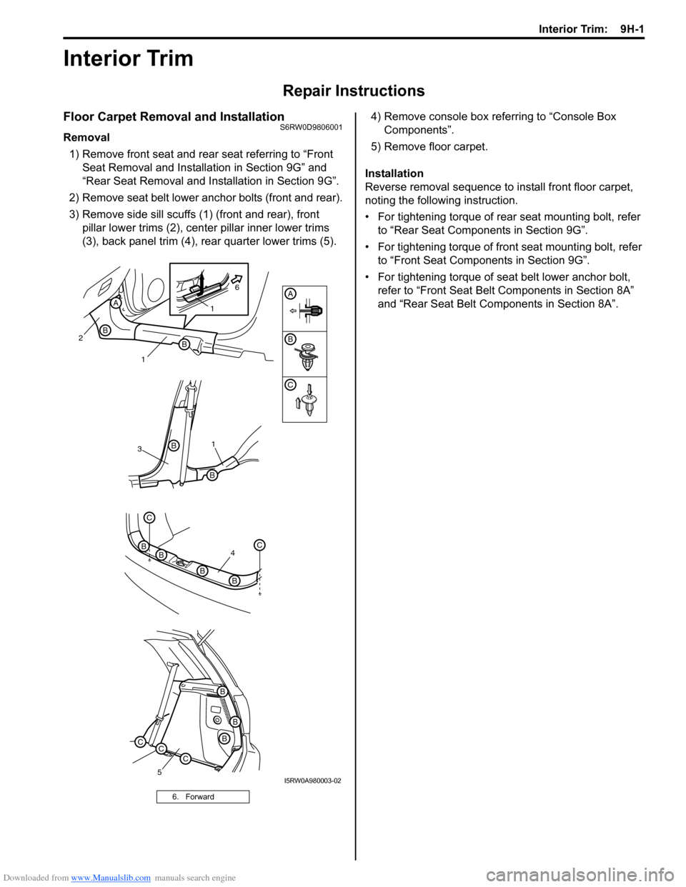
Floor Carpet Removal and InstallationS6RW0D9806001
Removal
1) Remove front seat and rear seat referring to “Front
Seat Removal and Installation in Section 9G” and
“Rear Seat Removal and Installation in Section 9G”.
2) Remove seat belt lower anchor bolts (front and rear).
3) Remove side sill scuffs (1) (front and rear), front
pillar lower trims (2), center pillar inner lower trims
(3), back panel trim (4), rear quarter lower trims (5).4) Remove console box referring to “Console Box
Components”.
5) Remove floor carpet.
Installation
Reverse removal sequence to install front floor carpet,
noting the following instruction.
• For tightening torque of rear seat mounting bolt, refer
to “Rear Seat Components in Section 9G”.
• For tightening torque of front seat mounting bolt, refer
to “Front Seat Components in Section 9G”.
• For tightening torque of seat belt lower anchor bolt,
refer to “Front Seat Belt Components in Section 8A”
and “Rear Seat Belt Components in Section 8A”.
6. Forward
B
C
A
4
C
BC
BB
B
31
B
B
5
B
B
B
CCC
2
1B
B
A1
6
I5RW0A980003-02
Page 1434 of 1556
Downloaded from www.Manualslib.com manuals search engine 9H-2 Interior Trim:
Head Lining Removal and InstallationS6RW0D9806002
WARNING!
Refer to “Air Bag System Service Warning in
Section 00” before starting service work.
Removal
1) Remove sun visor (1).
2) Remove dome lights of front (1) and center (2).3) Remove front pillar upper trims (1) rear side sill
scuffs (2), center pillar inner lower trims (3), center
pillar inner upper trims (4), back panel trim (5), rear
quarter lower trims (6) and rear quarter upper trims
(7).
1
I5RW0A980001-01
12
I5RW0A980002-01
[A]: With curtain air bag [B]: Without curtain air bag
32
4
B
B
B
C
A
A
AB
B
A
B
B
[A] [B]
7
6
BBBA
A
AAA
B
B
B
CCC
5
C
BC
BB
B
11
C
I5RW0A980004-03
Page 1437 of 1556

Downloaded from www.Manualslib.com manuals search engine Hood / Fenders / Doors: 9J-1
Body, Cab and Accessories
Hood / Fenders / Doors
Repair Instructions
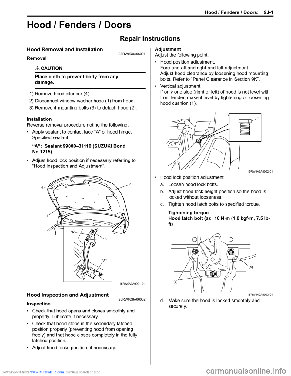
Hood Removal and InstallationS6RW0D9A06001
Removal
CAUTION!
Place cloth to prevent body from any
damage.
1) Remove hood silencer (4).
2) Disconnect window washer hose (1) from hood.
3) Remove 4 mounting bolts (3) to detach hood (2).
Installation
Reverse removal procedure noting the following.
• Apply sealant to contact face “A” of hood hinge.
Specified sealant.
“A”: Sealant 99000–31110 (SUZUKI Bond
No.1215)
• Adjust hood lock position if necessary referring to
“Hood Inspection and Adjustment”.
Hood Inspection and AdjustmentS6RW0D9A06002
Inspection
• Check that hood opens and closes smoothly and
properly. Lubricate if necessary.
• Check that hood stops in the secondary latched
position properly (preventing hood from opening
freely) and that hood closes completely in the fully
latched position.
• Adjust hood locks position, if necessary.Adjustment
Adjust the following point:
• Hood position adjustment.
Fore-and-aft and right-and-left adjustment.
Adjust hood clearance by loosening hood mounting
bolts. Refer to “Panel Clearance in Section 9K”.
• Vertical adjustment
If only one side (right or left) of hood is not level with
front fender, make it level by tightening or loosening
hood cushion (1).
• Hood lock position adjustment
a. Loosen hood lock bolts.
b. Adjust hood lock height position so the hood is
locked without looseness.
c. Tighten hood latch bolts to specified torque.
Tightening torque
Hood latch bolt (a): 10 N·m (1.0 kgf-m, 7.5 lb-
ft)
d. Make sure the hood is locked smoothly and
securely.
2
4
1
3 “A”
“A”
I5RW0A9A0001-01
1
I5RW0A9A0002-01
(a)(a)
I5RW0A9A0003-01