2006 SUZUKI SX4 meter
[x] Cancel search: meterPage 1273 of 1556
Downloaded from www.Manualslib.com manuals search engine Wiring Systems: 9A-106
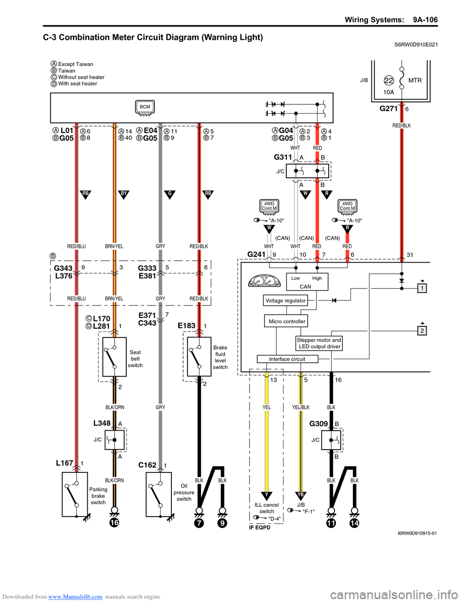
C-3 Combination Meter Circuit Diagram (Warning Light)S6RW0D910E021
J/BMTR
10A22
31
Stepper motor and
LED output driver
Voltage regulator
Micro controller
G2716
RED/BLK
516
YB
YEL/BLK
"F-1"
CAN
High Low
WHTWHTRED
RW
10G2419
7
L01
G05
RED/BLUBRN/YEL
L1671
Parking
brake
switch
1
2
A
A
16
BLK/ORN
BLK/ORN
J/C
L348B
B
J/C
G309
Seat
belt
switch
Oil
pressure
switch
J/B
13
Y
YEL
"D-4"
ILL cancel
switch
E371
C3437
G343
L37693G333
E38156
GRY
GRY
1C162
RED/BLK
RED/BLUBRN/YELGRYRED/BLK
E1831
Brake
fluid
level
switch
2
71114
BLK
BLK
BLK
9
BLKBLK
W
WHTRED
1
2
A
AB
B
J/C
G311
RBGBYRB
BCM
"A-10"
4WD
Cont.M
Interface circuit
RED
6
R"A-10"
4WD
Cont.M
(CAN) (CAN) (CAN)
IF EQPD
Except Taiwan
Taiwan
Without seat heater
With seat heater A
A
B
L170
L281C
D
G04
G05A
BE04
G05A
B
BCD
B
6
8AB14
40AB11
9AB5
7AB2
3AB4
1AB
I6RW0D910915-01
Page 1322 of 1556
Downloaded from www.Manualslib.com manuals search engine 9B-3 Lighting Systems:
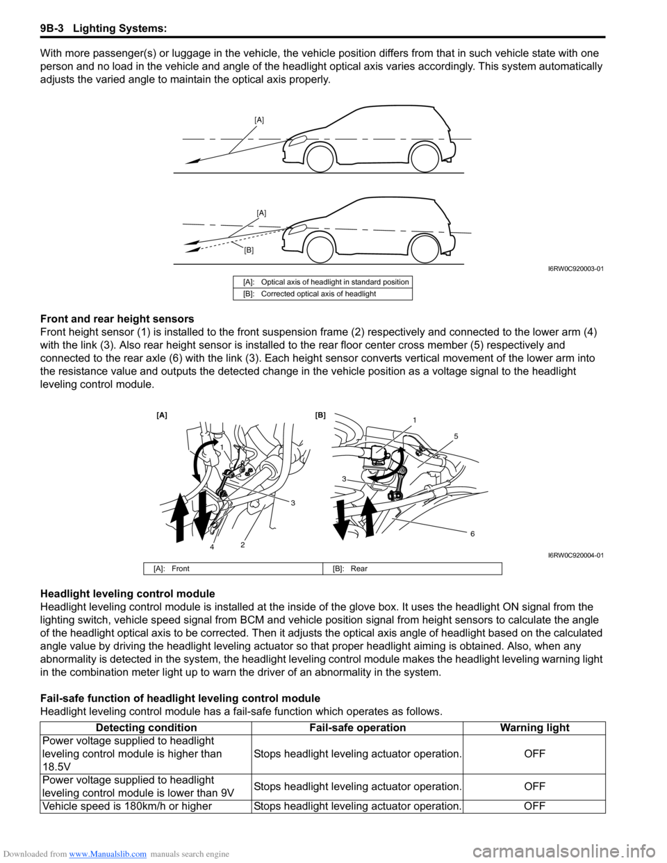
With more passenger(s) or luggage in the vehicle, the vehicle position differs from that in such vehicle state with one
person and no load in the vehicle and angle of the headlight optical axis varies accordingly. This system automatically
adjusts the varied angle to maintain the optical axis properly.
Front and rear height sensors
Front height sensor (1) is installed to the front suspension frame (2) respectively and connected to the lower arm (4)
with the link (3). Also rear height sensor is installed to the rear floor center cross member (5) respectively and
connected to the rear axle (6) with the link (3). Each height sensor converts vertical movement of the lower arm into
the resistance value and outputs the detected change in the vehicle position as a voltage signal to the headlight
leveling control module.
Headlight leveling control module
Headlight leveling control module is installed at the inside of the glove box. It uses the headlight ON signal from the
lighting switch, vehicle speed signal from BCM and vehicle position signal from height sensors to calculate the angle
of the headlight optical axis to be corrected. Then it adjusts the optical axis angle of headlight based on the calculated
angle value by driving the headlight leveling actuator so that proper headlight aiming is obtained. Also, when any
abnormality is detected in the system, the headlight leveling control module makes the headlight leveling warning light
in the combination meter light up to warn the driver of an abnormality in the system.
Fail-safe function of headlight leveling control module
Headlight leveling control module has a fail-safe function which operates as follows.
[A]
[A]
[B]
I6RW0C920003-01
[A]: Optical axis of headlight in standard position
[B]: Corrected optical axis of headlight
1
5
[A] [B]
6
3
1
2
3
4I6RW0C920004-01
[A]: Front [B]: Rear
Detecting condition Fail-safe operation Warning light
Power voltage supplied to headlight
leveling control module is higher than
18.5VStops headlight leveling actuator operation. OFF
Power voltage supplied to headlight
leveling control module is lower than 9VStops headlight leveling actuator operation. OFF
Vehicle speed is 180km/h or higher Stops headlight leveling actuator operation. OFF
Page 1324 of 1556
Downloaded from www.Manualslib.com manuals search engine 9B-5 Lighting Systems:
Schematic and Routing Diagram
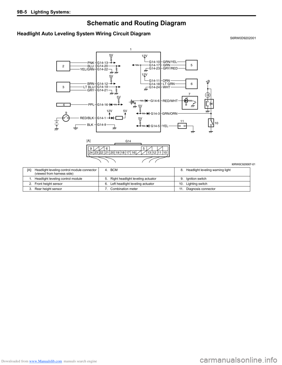
Headlight Auto Leveling System Wiring Circuit DiagramS6RW0D9202001
G14-12G14-19G14-21
G14-10
G14-23
+B
5V
5V
GRN/YEL
GRY/RED
BLK
G14-112V
BRNLT BLUGRY
RED/BLK
3
G14-13G14-20G14-22
5V
PNKBLUYEL/GRN2
45
9
10 11 1
5V
5V
12V
G14-16
G14-3
PPL
GRN/ORN
5V
G14-5YEL
G14-17GRN
G14-11
G14-24
ORN
WHT6 12VG14-18LT GRN
7
8
G14-6
G14-9
RED/WHT
G14
10 11 12 13 16 17 18 19 205 6 9
21 22 23 24
[A]
I6RW0C920007-01
[A]: Headlight leveling control module connector
(viewed from harness side)4. BCM 8. Headlight leveling warning light
1. Headlight leveling control module 5. Right headlight leveling actuator 9. Ignition switch
2. Front height sensor 6. Left headlight leveling actuator 10. Lighting switch
3. Rear height sensor 7. Combination meter 11. Diagnosis connector
Page 1326 of 1556
Downloaded from www.Manualslib.com manuals search engine 9B-7 Lighting Systems:
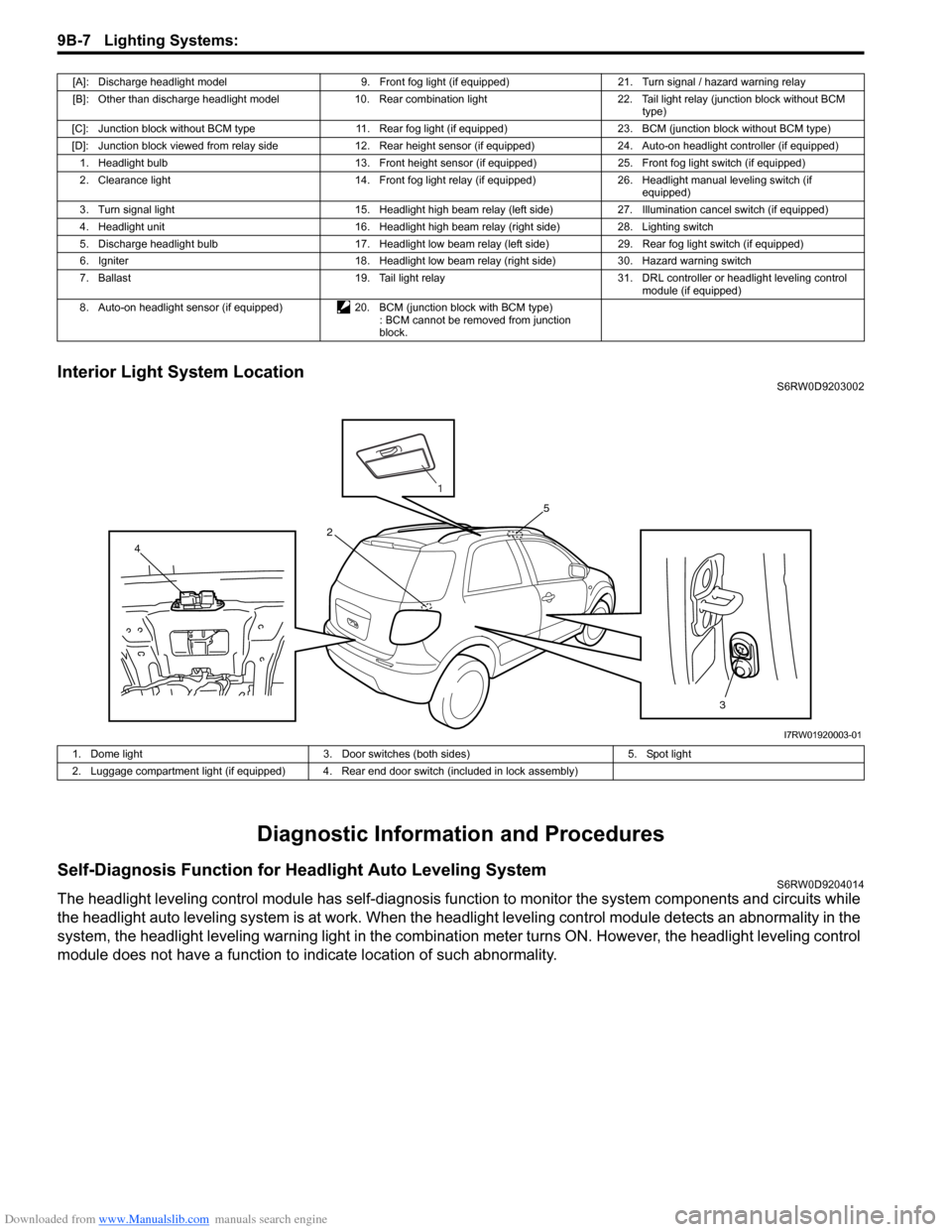
Interior Light System LocationS6RW0D9203002
Diagnostic Information and Procedures
Self-Diagnosis Function for Headlight Auto Leveling SystemS6RW0D9204014
The headlight leveling control module has self-diagnosis function to monitor the system components and circuits while
the headlight auto leveling system is at work. When the headlight leveling control module detects an abnormality in the
system, the headlight leveling warning light in the combination meter turns ON. However, the headlight leveling control
module does not have a function to indicate location of such abnormality.
[A]: Discharge headlight model 9. Front fog light (if equipped) 21. Turn signal / hazard warning relay
[B]: Other than discharge headlight model 10. Rear combination light 22. Tail light relay (junction block without BCM
type)
[C]: Junction block without BCM type 11. Rear fog light (if equipped) 23. BCM (junction block without BCM type)
[D]: Junction block viewed from relay side 12. Rear height sensor (if equipped) 24. Auto-on headlight controller (if equipped)
1. Headlight bulb 13. Front height sensor (if equipped) 25. Front fog light switch (if equipped)
2. Clearance light 14. Front fog light relay (if equipped) 26. Headlight manual leveling switch (if
equipped)
3. Turn signal light 15. Headlight high beam relay (left side) 27. Illumination cancel switch (if equipped)
4. Headlight unit 16. Headlight high beam relay (right side) 28. Lighting switch
5. Discharge headlight bulb 17. Headlight low beam relay (left side) 29. Rear fog light switch (if equipped)
6. Igniter 18. Headlight low beam relay (right side) 30. Hazard warning switch
7. Ballast 19. Tail light relay 31. DRL controller or headlight leveling control
module (if equipped)
8. Auto-on headlight sensor (if equipped) 20. BCM (junction block with BCM type)
: BCM cannot be removed from junction
block.
3 4
5
2
1
I7RW01920003-01
1. Dome light 3. Door switches (both sides) 5. Spot light
2. Luggage compartment light (if equipped) 4. Rear end door switch (included in lock assembly)
Page 1332 of 1556
Downloaded from www.Manualslib.com manuals search engine 9B-13 Lighting Systems:
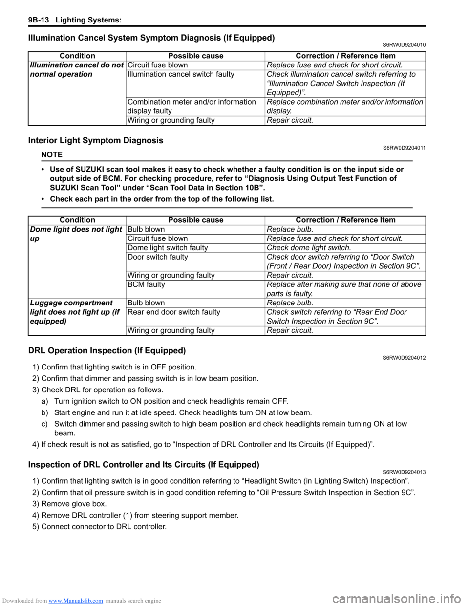
Illumination Cancel System Symptom Diagnosis (If Equipped)S6RW0D9204010
Interior Light Symptom DiagnosisS6RW0D9204011
NOTE
• Use of SUZUKI scan tool makes it easy to check whether a faulty condition is on the input side or
output side of BCM. For checking procedure, refer to “Diagnosis Using Output Test Function of
SUZUKI Scan Tool” under “Scan Tool Data in Section 10B”.
• Check each part in the order from the top of the following list.
DRL Operation Inspection (If Equipped)S6RW0D9204012
1) Confirm that lighting switch is in OFF position.
2) Confirm that dimmer and passing switch is in low beam position.
3) Check DRL for operation as follows.
a) Turn ignition switch to ON position and check headlights remain OFF.
b) Start engine and run it at idle speed. Check headlights turn ON at low beam.
c) Switch dimmer and passing switch to high beam position and check headlights remain turning ON at low
beam.
4) If check result is not as satisfied, go to “Inspection of DRL Controller and Its Circuits (If Equipped)”.
Inspection of DRL Controller and Its Circuits (If Equipped)S6RW0D9204013
1) Confirm that lighting switch is in good condition referring to “Headlight Switch (in Lighting Switch) Inspection”.
2) Confirm that oil pressure switch is in good condition referring to “Oil Pressure Switch Inspection in Section 9C”.
3) Remove glove box.
4) Remove DRL controller (1) from steering support member.
5) Connect connector to DRL controller.Condition Possible cause Correction / Reference Item
Illumination cancel do not
normal operationCircuit fuse blownReplace fuse and check for short circuit.
Illumination cancel switch faultyCheck illumination cancel switch referring to
“Illumination Cancel Switch Inspection (If
Equipped)”.
Combination meter and/or information
display faultyReplace combination meter and/or information
display.
Wiring or grounding faultyRepair circuit.
Condition Possible cause Correction / Reference Item
Dome light does not light
upBulb blownReplace bulb.
Circuit fuse blownReplace fuse and check for short circuit.
Dome light switch faultyCheck dome light switch.
Door switch faultyCheck door switch referring to “Door Switch
(Front / Rear Door) Inspection in Section 9C”.
Wiring or grounding faultyRepair circuit.
BCM faultyReplace after making sure that none of above
parts is faulty.
Luggage compartment
light does not light up (if
equipped)Bulb blownReplace bulb.
Rear end door switch faultyCheck switch referring to “Rear End Door
Switch Inspection in Section 9C”.
Wiring or grounding faultyRepair circuit.
Page 1335 of 1556
Downloaded from www.Manualslib.com manuals search engine Lighting Systems: 9B-16
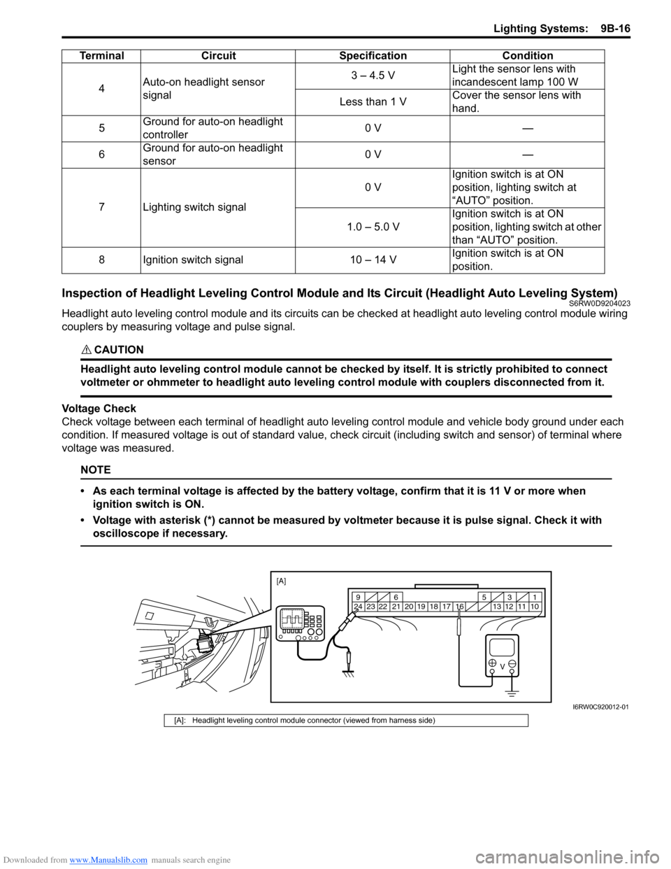
Inspection of Headlight Leveling Control Module and Its Circuit (Headlight Auto Leveling System)S6RW0D9204023
Headlight auto leveling control module and its circuits can be checked at headlight auto leveling control module wiring
couplers by measuring voltage and pulse signal.
CAUTION!
Headlight auto leveling control module cannot be checked by itself. It is strictly prohibited to connect
voltmeter or ohmmeter to headlight auto leveling control module with couplers disconnected from it.
Voltage Check
Check voltage between each terminal of headlight auto leveling control module and vehicle body ground under each
condition. If measured voltage is out of standard value, check circuit (including switch and sensor) of terminal where
voltage was measured.
NOTE
• As each terminal voltage is affected by the battery voltage, confirm that it is 11 V or more when
ignition switch is ON.
• Voltage with asterisk (*) cannot be measured by voltmeter because it is pulse signal. Check it with
oscilloscope if necessary.
4Auto-on headlight sensor
signal3 – 4.5 VLight the sensor lens with
incandescent lamp 100 W
Less than 1 VCover the sensor lens with
hand.
5Ground for auto-on headlight
controller0 V —
6Ground for auto-on headlight
sensor0 V —
7 Lighting switch signal0 VIgnition switch is at ON
position, lighting switch at
“AUTO” position.
1.0 – 5.0 VIgnition switch is at ON
position, lighting switch at other
than “AUTO” position.
8 Ignition switch signal 10 – 14 VIgnition switch is at ON
position. Terminal Circuit Specification Condition
V
10 11 12 13 16 17 18 19 2031 5 6 9
21 22 23 24
[A]
I6RW0C920012-01
[A]: Headlight leveling control module connector (viewed from harness side)
Page 1350 of 1556
Downloaded from www.Manualslib.com manuals search engine 9B-31 Lighting Systems:
Without initialization of the headlight auto leveling
system, it is not possible to obtain its proper function.
Also, if the headlight auto leveling system is not
initialized after replacing the headlight leveling control
module, the headlight leveling warning light in the
combination meter flashes.
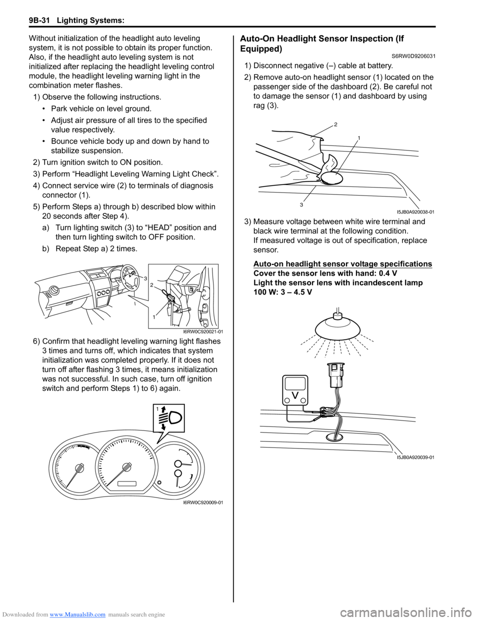
1) Observe the following instructions.
• Park vehicle on level ground.
• Adjust air pressure of all tires to the specified
value respectively.
• Bounce vehicle body up and down by hand to
stabilize suspension.
2) Turn ignition switch to ON position.
3) Perform “Headlight Leveling Warning Light Check”.
4) Connect service wire (2) to terminals of diagnosis
connector (1).
5) Perform Steps a) through b) described blow within
20 seconds after Step 4).
a) Turn lighting switch (3) to “HEAD” position and
then turn lighting switch to OFF position.
b) Repeat Step a) 2 times.
6) Confirm that headlight leveling warning light flashes
3 times and turns off, which indicates that system
initialization was completed properly. If it does not
turn off after flashing 3 times, it means initialization
was not successful. In such case, turn off ignition
switch and perform Steps 1) to 6) again.Auto-On Headlight Sensor Inspection (If
Equipped)
S6RW0D9206031
1) Disconnect negative (–) cable at battery.
2) Remove auto-on headlight sensor (1) located on the
passenger side of the dashboard (2). Be careful not
to damage the sensor (1) and dashboard by using
rag (3).
3) Measure voltage between white wire terminal and
black wire terminal at the following condition.
If measured voltage is out of specification, replace
sensor.
Auto-on headlight sensor voltage specifications
Cover the sensor lens with hand: 0.4 V
Light the sensor lens with incandescent lamp
100 W: 3 – 4.5 V3
1
2
I6RW0C920021-01
1
I6RW0C920009-01
2
1
3I5JB0A920038-01
I5JB0A920039-01
Page 1353 of 1556
Downloaded from www.Manualslib.com manuals search engine Instrumentation / Driver Info. / Horn: 9C-1
Body, Cab and Accessories
Instrumentation / Driver Info. / Horn
Precautions
Precautions in Diagnosing Troubles for Combination MeterS6RW0D9300001
Combination meter uses signals (information) from each control module by CAN communication to control
speedometer, tachometer, fuel meter, engine coolant temp meter, warning light and indicator light (other than air bag
warning light, EPS warning light, headlight leveling warning light (if equipped), rear fog light indicator light (if
equipped), high beam indicator light and turn signal indicator light). Therefor, check that no DTC is detected in each
module before performing combination meter symptom diagnosis. If any DTC is detected, correct trouble indicated by
that DTC troubleshooting first.
General Description
CAN Communication System DescriptionS6RW0D9301001
Refer to “CAN Communication System Description in Section 1A” for CAN communication system description.
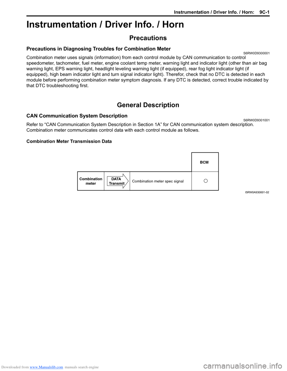
Combination meter communicates control data with each control module as follows.
Combination Meter Transmission Data
BCM
Combination
meterDATA
TransmitCombination meter spec signal
I5RW0A930001-02