2006 SUZUKI SX4 instrument cluster
[x] Cancel search: instrument clusterPage 55 of 1556

Downloaded from www.Manualslib.com manuals search engine Engine General Information and Diagnosis: 1A-5
General Description
Statement on Cleanliness and CareS6RW0D1101001
An automobile engine is a combination of many
machined, honed, polished and lapped surfaces with
tolerances that are measured in the thousands of an
millimeter (ten thousands of an inch).
Accordingly, when any internal engine parts are
serviced, care and cleanliness are important.
It should be understood that proper cleaning and
protection of machined surfaces and friction areas is part
of the repair procedure. This is considered standard
shop practice even if not specifically stated.
• A liberal coating of engine oil should be applied to
friction areas during assembly to protect and lubricate
the surfaces on initial operation.
• Whenever valve train components, pistons, piston
rings, connecting rods, rod bearings, and crankshaft
journal bearings are removed for service, they should
be retained in order.
At the time of installation, they should be installed in
the same locations and with the same mating
surfaces as when removed.
• Battery cables should be disconnected before any
major work is performed on the engine.
Failure to disconnect cables may result in damage to
wire harness or other electrical parts.
• The four cylinders of the engine are identified by
numbers; No.1 (1), No.2 (2), No.3 (3) and No.4 (4)
counted from crankshaft pulley side to flywheel side.
Engine Diagnosis General DescriptionS6RW0D1101002
NOTE
There are two types of OBD system
depending on the vehicle specification.
For identification, refer to “Precaution on On-
Board Diagnostic (OBD) System”.
This vehicle is equipped with an engine and emission
control system which are under control of ECM.
The engine and emission control system in this vehicle
are controlled by ECM. ECM has an On-Board
Diagnostic system which detects a malfunction in this
system and abnormality of those parts that influence the
engine exhaust emission. When diagnosing engine
troubles, be sure to have full understanding of the outline
of “On-Board Diagnostic System Description” and each
item in “Precautions in Diagnosing Trouble” and execute
diagnosis according to “Engine and Emission Control
System Check”.
There is a close relationship between the engine
mechanical, engine cooling system, ignition system,
exhaust system, etc. and the engine and emission
control system in their structure and operation. In case of
an engine trouble, even when the malfunction indicator
lamp (MIL) doesn’t turn ON, it should be diagnosed
according to “Engine and Emission Control System
Check”.
On-Board Diagnostic System DescriptionS6RW0D1101003
NOTE
There are two types of OBD system
depending on the vehicle specification.
For identification, refer to “Precaution on On-
Board Diagnostic (OBD) System”.
Euro OBD model
ECM in this vehicle has the following functions.
• When the ignition switch is turned ON with the engine
at a stop, malfunction indicator lamp (MIL) (1) turns
ON to check the circuit of the malfunction indicator
lamp (1).
• When ECM detects a malfunction which gives an
adverse effect to vehicle emission while the engine is
running, it makes the malfunction indicator lamp (1) in
the meter cluster of the instrument panel turn ON or
flash (flashing only when detecting a misfire which
can cause damage to the catalyst) and stores the
malfunction area in its memory.
(If it detects that continuously 3 driving cycles are
normal after detecting a malfunction, however, it
makes MIL (1) turn OFF although DTC stored in its
memory will remain.)
1
234
I3RM0A110001-01
Page 478 of 1556

Downloaded from www.Manualslib.com manuals search engine 3-ii Table of Contents
DTC U0100: Lost Communication with ECM .... 3B-27
DTC U0121: Lost Communication with ABS /
ESP® Control Module..................................... 3B-27
DTC U0155: Lost Communication with
Instrument Panel Cluster (IPC) Control
Module ............................................................ 3B-27
Inspection of 4WD Control Module and Its
Circuits ............................................................ 3B-27
Repair Instructions ............................................3B-30
Rear Differential Oil Level Check ...................... 3B-30
Rear Differential Oil Change ............................. 3B-30
2WD/4WD Switch Removal and Installation ..... 3B-31
2WD/4WD Switch Inspection ............................ 3B-31
4WD Control Module Removal and
Installation ....................................................... 3B-31
Coupling Air Temperature Sensor Removal
and Installation ................................................ 3B-31
Coupling Air Temperature Sensor Inspection ... 3B-32
Coupling Assembly Inspection .......................... 3B-32
Rear Differential Mountings Components ......... 3B-33
Front Mounting Arm and/or Rear Mounting
Bracket Assembly Removal and Installation ... 3B-34
Rear Mounting Bracket Assembly
Disassembly and Reassembly ........................ 3B-34
Rear Differential Dismounting and
Remounting ..................................................... 3B-34
Rear Differential Components ........................... 3B-35
Rear Differential Disassembly and
Reassembly .................................................... 3B-36
Rear Differential Inspection ............................... 3B-47
Specifications .....................................................3B-48
Tightening Torque Specifications ...................... 3B-48
Special Tools and Equipment ...........................3B-48
Recommended Service Material ....................... 3B-48
Special Tool ...................................................... 3B-49
Transfer .................................................... 3C-1
General Description ............................................. 3C-1
Transfer Description ............................................ 3C-1Diagnostic Information and Procedures ............3C-1
Transfer Symptom Diagnosis..............................3C-1
Repair Instructions ..............................................3C-2
Transfer Oil Level Check.....................................3C-2
Transfer Oil Change ............................................3C-2
Transfer Dismounting and Remounting ..............3C-3
Transfer Assembly Components .........................3C-4
Transfer Assembly Disassembly and
Reassembly ......................................................3C-5
Reduction Drive Gear Assembly Disassembly
and Reassembly ...............................................3C-7
Reduction Driven Gear Assembly
Disassembly and Reassembly ..........................3C-8
Transfer Right Case and Left Case
Disassembly and Reassembly ..........................3C-9
Transfer Output Retainer Assembly
Disassembly and Reassembly ........................3C-10
Transfer Assembly Inspection ...........................3C-14
Bevel Gear Tooth Contact Inspection ...............3C-14
Specifications .....................................................3C-16
Tightening Torque Specifications ......................3C-16
Special Tools and Equipment ...........................3C-17
Recommended Service Material .......................3C-17
Special Tool ......................................................3C-17
Propeller Shafts ....................................... 3D-1
Precautions ...........................................................3D-1
Propeller Shaft Caution .......................................3D-1
General Description .............................................3D-1
Propeller Shaft Construction ...............................3D-1
Diagnostic Information and Procedures ............3D-1
Propeller Shaft Symptom Diagnosis ...................3D-1
Repair Instructions ..............................................3D-2
Propeller Shaft Joint Check.................................3D-2
Propeller Shaft Assembly Removal and
Installation .........................................................3D-2
Propeller Shaft Inspection ...................................3D-2
Specifications .......................................................3D-3
Tightening Torque Specifications ........................3D-3
Page 509 of 1556
Downloaded from www.Manualslib.com manuals search engine Differential: 3B-12
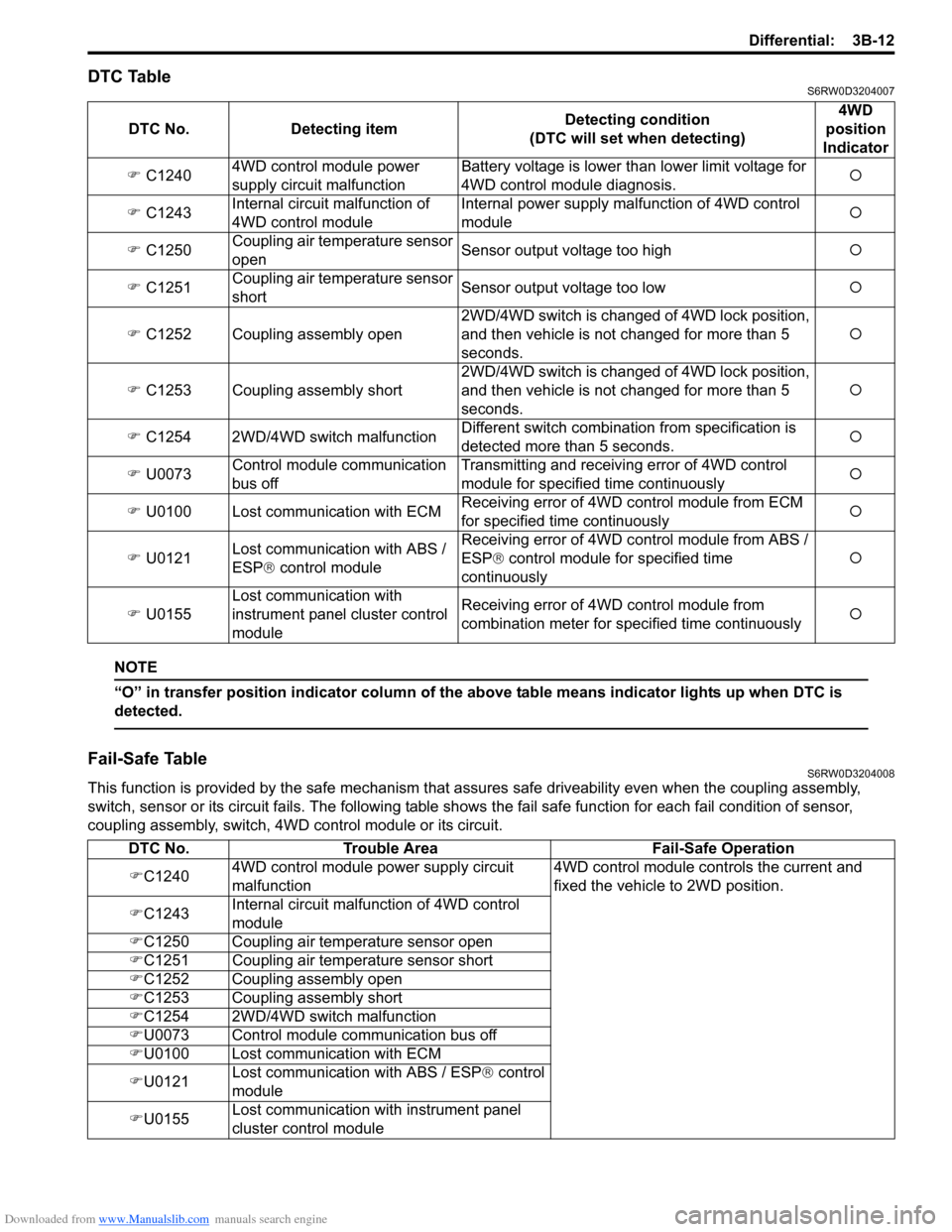
DTC TableS6RW0D3204007
NOTE
“O” in transfer position indicator column of the above table means indicator lights up when DTC is
detected.
Fail-Safe TableS6RW0D3204008
This function is provided by the safe mechanism that assures safe driveability even when the coupling assembly,
switch, sensor or its circuit fails. The following table shows the fail safe function for each fail condition of sensor,
coupling assembly, switch, 4WD control module or its circuit. DTC No. Detecting itemDetecting condition
(DTC will set when detecting)4WD
position
Indicator
�) C12404WD control module power
supply circuit malfunctionBattery voltage is lower than lower limit voltage for
4WD control module diagnosis.�{
�) C1243Internal circuit malfunction of
4WD control moduleInternal power supply malfunction of 4WD control
module�{
�) C1250Coupling air temperature sensor
openSensor output voltage too high�{
�) C1251Coupling air temperature sensor
shortSensor output voltage too low�{
�) C1252 Coupling assembly open2WD/4WD switch is changed of 4WD lock position,
and then vehicle is not changed for more than 5
seconds.�{
�) C1253 Coupling assembly short2WD/4WD switch is changed of 4WD lock position,
and then vehicle is not changed for more than 5
seconds.�{
�) C1254 2WD/4WD switch malfunctionDifferent switch combination from specification is
detected more than 5 seconds.�{
�) U0073Control module communication
bus offTransmitting and receiving error of 4WD control
module for specified time continuously�{
�) U0100 Lost communication with ECMReceiving error of 4WD control module from ECM
for specified time continuously�{
�) U0121Lost communication with ABS /
ESP® control moduleReceiving error of 4WD control module from ABS /
ESP® control module for specified time
continuously�{
�) U0155Lost communication with
instrument panel cluster control
moduleReceiving error of 4WD control module from
combination meter for specified time continuously�{
DTC No. Trouble Area Fail-Safe Operation
�)C12404WD control module power supply circuit
malfunction4WD control module controls the current and
fixed the vehicle to 2WD position.
�)C1243Internal circuit malfunction of 4WD control
module
�)C1250 Coupling air temperature sensor open
�)C1251 Coupling air temperature sensor short
�)C1252 Coupling assembly open
�)C1253 Coupling assembly short
�)C1254 2WD/4WD switch malfunction
�)U0073 Control module communication bus off
�)U0100 Lost communication with ECM
�)U0121Lost communication with ABS / ESP® control
module
�)U0155Lost communication with instrument panel
cluster control module
Page 524 of 1556

Downloaded from www.Manualslib.com manuals search engine 3B-27 Differential:
DTC U0073: Control Module Communication Bus OffS6RW0D3204022
Refer to “Troubleshooting for CAN-DTC in Section 1A”.
DTC U0100: Lost Communication with ECMS6RW0D3204023
Refer to “Troubleshooting for CAN-DTC in Section 1A”.
DTC U0121: Lost Communication with ABS / ESP® Control ModuleS6RW0D3204024
Refer to “Troubleshooting for CAN-DTC in Section 1A”.
DTC U0155: Lost Communication with Instrument Panel Cluster (IPC) Control ModuleS6RW0D3204025
Refer to “Troubleshooting for CAN-DTC in Section 1A”.
Inspection of 4WD Control Module and Its CircuitsS6RW0D3204026
4WD control module and its circuits can be checked at coupler connected to 4WD control module by measuring
voltage, pulse signal.
CAUTION!
4WD control module cannot be checked by itself. It is strictly prohibited to connect voltmeter or
ohmmeter to 4WD control module with couplers disconnected from it.
Voltage and Signal Check
1) Check voltage using voltmeter (1) connected to each terminal of couplers.
2) Check signal using oscilloscope (2) connected to each terminal of couplers.
NOTE
• As each terminal voltage is affected by the battery voltage, confirm that it is 11 V or more when
ignition switch is turned ON.
• Pulse signal cannot be measured by voltmeter. It can be measured by oscilloscope.
• Item with asterisk (*) in normal voltage column can be read only by oscilloscope.
12
I4JA01332053-01
Page 1367 of 1556
Downloaded from www.Manualslib.com manuals search engine Instrumentation / Driver Info. / Horn: 9C-15
3) Remove center ventilation louver referring to Step 1)
and 2) of “Information Display (Clock) Removal and
Installation”.
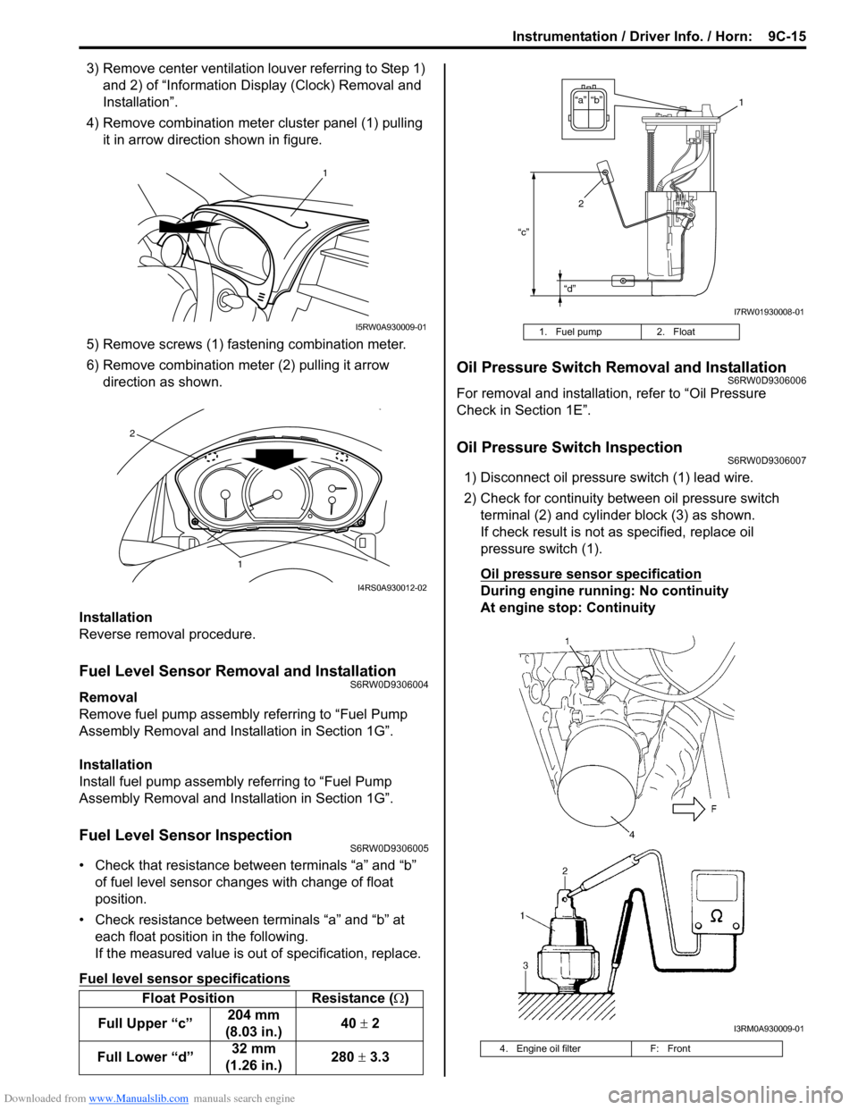
4) Remove combination meter cluster panel (1) pulling
it in arrow direction shown in figure.
5) Remove screws (1) fastening combination meter.
6) Remove combination meter (2) pulling it arrow
direction as shown.
Installation
Reverse removal procedure.
Fuel Level Sensor Removal and InstallationS6RW0D9306004
Removal
Remove fuel pump assembly referring to “Fuel Pump
Assembly Removal and Installation in Section 1G”.
Installation
Install fuel pump assembly referring to “Fuel Pump
Assembly Removal and Installation in Section 1G”.
Fuel Level Sensor InspectionS6RW0D9306005
• Check that resistance between terminals “a” and “b”
of fuel level sensor changes with change of float
position.
• Check resistance between terminals “a” and “b” at
each float position in the following.
If the measured value is out of specification, replace.
Fuel level sensor specifications
Oil Pressure Switch Removal and InstallationS6RW0D9306006
For removal and installation, refer to “Oil Pressure
Check in Section 1E”.
Oil Pressure Switch InspectionS6RW0D9306007
1) Disconnect oil pressure switch (1) lead wire.
2) Check for continuity between oil pressure switch
terminal (2) and cylinder block (3) as shown.
If check result is not as specified, replace oil
pressure switch (1).
Oil pressure sensor specification
During engine running: No continuity
At engine stop: Continuity
Float Position Resistance (Ω)
Full Upper “c”204 mm
(8.03 in.)40 ± 2
Full Lower “d”32 mm
(1.26 in.)280 ± 3.3
1
I5RW0A930009-01
1
2
I4RS0A930012-02
1. Fuel pump 2. Float
4. Engine oil filter F: Front
“c”
“d”
“b” “a”1
2
I7RW01930008-01
I3RM0A930009-01
Page 1372 of 1556
Downloaded from www.Manualslib.com manuals search engine 9C-20 Instrumentation / Driver Info. / Horn:
GPS Antenna Removal and Installation (If
Equipped)
S6RW0D9306027
Removal
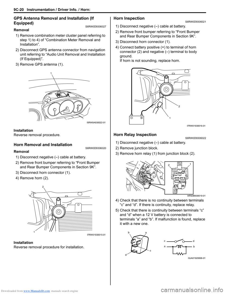
1) Remove combination meter cluster panel referring to
step 1) to 4) of “Combination Meter Removal and
Installation”.
2) Disconnect GPS antenna connector from navigation
unit referring to “Audio Unit Removal and Installation
(If Equipped)”.
3) Remove GPS antenna (1).
Installation
Reverse removal procedure.
Horn Removal and InstallationS6RW0D9306020
Removal
1) Disconnect negative (–) cable at battery.
2) Remove front bumper referring to “Front Bumper
and Rear Bumper Components in Section 9K”.
3) Disconnect horn connector (1).
4) Remove horn (2).
Installation
Reverse removal procedure for installation.
Horn InspectionS6RW0D9306021
1) Disconnect negative (–) cable at battery.
2) Remove front bumper referring to “Front Bumper
and Rear Bumper Components in Section 9K”.
3) Disconnect horn connector (1).
4) Connect battery positive (+) to terminal of horn
connector (2) and negative (–) terminal to body
ground.
If horn is not sounding, replace horn.
Horn Relay InspectionS6RW0D9306022
1) Disconnect negative (–) cable at battery.
2) Remove junction block.
3) Remove horn relay (1) from junction block (2).
4) Check that there is no continuity between terminals
“c” and “d”. If there is continuity, replace relay.
5) Check that there is continuity between terminals “c”
and “d” when a 12 V battery is connected to
terminals “a” and “b”. If malfunction is found, replace
it with a new one.
1
I5RW0A930022-01
12I7RW01930015-01
12
I7RW01930016-01
1
2
I4RS0B930018-01
ba
c
dc
ad
bI3JA01920006-01
Page 1471 of 1556
Downloaded from www.Manualslib.com manuals search engine Table of Contents 10- i
10
Section 10
CONTENTS
Control Systems
Precautions ............................................... 10-1
Precautions........................................................... 10-1
Precautions for Control Systems......................... 10-1
Body Electrical Control System ........... 10B-1
Precautions......................................................... 10B-1
Precautions in Diagnosing Trouble ................... 10B-1
General Description ........................................... 10B-1
BCM General Description ................................. 10B-1
CAN Communication System Description......... 10B-1
Theft Deterrent Light ......................................... 10B-2
Security Alarm Description (If Equipped) .......... 10B-2
Schematic and Routing Diagram ...................... 10B-3
Body Electrical Control System Wiring Circuit
Diagram .......................................................... 10B-3
Connector Layout Diagram of BCM and
Junction Block ................................................. 10B-6
Component Location ......................................... 10B-7
BCM and Related System Component
Location .......................................................... 10B-7
Diagnostic Information and Procedures .......... 10B-8
BCM Self-Diagnosis Function ........................... 10B-8
Body Electrical Control System Check.............. 10B-9
Scan Tool Data ............................................... 10B-11
DTC Table ....................................................... 10B-13
DTC Check ..................................................... 10B-14
DTC Clearance ............................................... 10B-15
BCM Power Circuit and Ground Circuit Check 10B-16
DTC B1133 (DTC No. 1133): Battery Voltage
Too High ....................................................... 10B-17
DTC B1141 / DTC B1142 (No. 1141 / No.
1142) Outside Air Temperature (Ambient
Temp.) Sensor Circuit Malfunction ................ 10B-18
DTC B1150 (No. 1150): Air Bag
Communication Circuit Malfunction .............. 10B-19
DTC B1157 (No. 1157) Air Bag Deployment
Signal Input ................................................... 10B-20
DTC B1170 (No. 1170): EEPROM Access
Error .............................................................. 10B-20
DTC U0073 (No. 0073): Control Module
Communication Bus Off ................................ 10B-20
DTC U0100 (No. 0100): Lost Communication
with ECM....................................................... 10B-20DTC U0101 (No. 0101): Lost Communication
with TCM ....................................................... 10B-20
DTC U0155 (No. 0155): Lost Communication
with Instrument Panel Cluster (IPC) Control
Module .......................................................... 10B-20
DTC U1144 (No. 1144): Lost Communication
with Keyless Start Control Module ................ 10B-20
Inspection of BCM and Its Circuits .................. 10B-21
Repair Instructions ..........................................10B-28
BCM (Included in Junction Block) Removal
and Installation .............................................. 10B-28
Security Alarm Mode Selection Procedure (If
Equipped) ...................................................... 10B-29
Outside Air Temperature Sensor Removal
and Installation .............................................. 10B-29
Outside Air Temperature Sensor Inspection ... 10B-29
Special Tools and Equipment .........................10B-29
Special Tool .................................................... 10B-29
Immobilizer Control System ................. 10C-1
Precautions.........................................................10C-1
Precautions in Diagnosing Troubles .................10C-1
Precaution in Replacing ECM ...........................10C-1
Precaution in Replacing Ignition Key ................10C-1
Precautions in Handling Immobilizer Control
System ............................................................10C-1
General Description ...........................................10C-2
Immobilizer Control System Introduction ..........10C-2
On-Board Diagnostic System Description
(Self-diagnosis Function)................................10C-2
Schematic and Routing Diagram ......................10C-3
Immobilizer Control System Wiring Circuit
Diagram...........................................................10C-3
Component Location .........................................10C-5
Immobilizer Control System Components
Location...........................................................10C-5
Diagnostic Information and Procedures ..........10C-5
Immobilizer Control System Check ...................10C-5
DTC Check........................................................10C-6
DTC Clearance .................................................10C-6
DTC Table .........................................................10C-7
Scan Tool Data .................................................10C-8
Immobilizer Indicator Light Does Not Come
ON with Ignition Switch ON and Engine Stop ..10C-9
Page 1486 of 1556
Downloaded from www.Manualslib.com manuals search engine 10B-13 Body Electrical Control System:
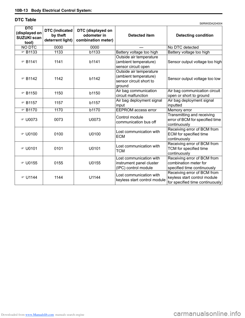
DTC TableS6RW0DA204004
DTC
(displayed on
SUZUKI scan
tool)DTC (indicated
by theft
deterrent light) DTC (displayed on
odometer in
combination meter) Detected item Detecting condition
NO DTC 0000 0000 — No DTC detected
�) B1133 1133 b1133 Battery voltage too high Battery voltage too high
�) B1141 1141 b1141Outside air temperature
(ambient temperature)
sensor circuit openSensor output voltage too high
�) B1142 1142 b1142Outside air temperature
(ambient temperature)
sensor circuit short to
groundSensor output voltage too low
�) B1150 1150 b1150Air bag communication
circuit malfunctionAir bag communication circuit
open or short to ground
�) B1157 1157 b1157Air bag deployment signal
inputAir bag deployment signal
inputted
�) B1170 1170 b1170 EEPROM access error Memory error
�) U0073 0073 U0073Control module
communication bus offTransmitting and receiving
error of BCM for specified time
continuously
�) U0100 0100 U0100Lost communication with
ECMReceiving error of BCM from
ECM for specified time
continuously
�) U0101 0101 U0101Lost communication with
TCMReceiving error of BCM from
TCM for specified time
continuously
�) U0155 0155 U0155Lost communication with
instrument panel cluster
(IPC) control moduleReceiving error of BCM from
combination meter for
specified time continuously
�) U1144 1144 U1144Lost communication with
keyless start control moduleReceiving error of BCM from
keyless start control module
for specified time continuously