2006 SUZUKI SX4 steering
[x] Cancel search: steeringPage 1366 of 1556
Downloaded from www.Manualslib.com manuals search engine 9C-14 Instrumentation / Driver Info. / Horn:
Repair Instructions
Ignition Switch Removal and InstallationS6RW0D9306001
Removal
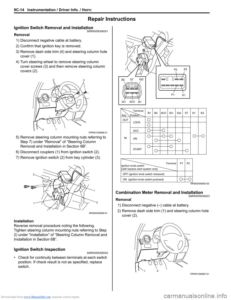
1) Disconnect negative cable at battery.
2) Confirm that ignition key is removed.
3) Remove dash side trim (4) and steering column hole
cover (1).
4) Turn steering wheel to remove steering column
cover screws (3) and then remove steering column
covers (2).
5) Remove steering column mounting nuts referring to
Step 7) under “Removal” of “Steering Column
Removal and Installation in Section 6B”.
6) Disconnect couplers (1) from ignition switch (2).
7) Remove ignition switch (2) from key cylinder (3).
Installation
Reverse removal procedure noting the following.
Tighten steering column mounting nuts referring to Step
2) under “Installation” of “Steering Column Removal and
Installation in Section 6B”.
Ignition Switch InspectionS6RW0D9306002
• Check for continuity between terminals at each switch
position. If check result is not as specified, replace
switch.
Combination Meter Removal and InstallationS6RW0D9306003
Removal
1) Disconnect negative (–) cable at battery.
2) Remove dash side trim (1) and steering column hole
cover (2).
2
3
1
4I7RW01930006-01
11
2
3
I4RS0A930008-01
PositionTerminal
LOCK
ACC
ON
START OUT
INK2 K1 ST IG2 IG1 ACC B1 B2
Ignition knob switch
(with keyless start system only)
ACC
IG1IG2
ST
B2
B1K2
K1
P2
P1
Terminal
OFF (ignition knob switch released)
ON (ignition knob switch pushsed)P1 P2
Key
I5RS0D930003-02
21I7RW01930007-01
Page 1369 of 1556
Downloaded from www.Manualslib.com manuals search engine Instrumentation / Driver Info. / Horn: 9C-17
Outside Air Temperature Sensor Removal and
Installation (If Equipped)
S6RW0D9306013
Removal
1) Disconnect negative (–) cable at battery.
2) Remove front bumper referring to “Front Bumper
and Rear Bumper Components in Section 9K”.
3) Disconnect connector from outside air temperature
sensor.
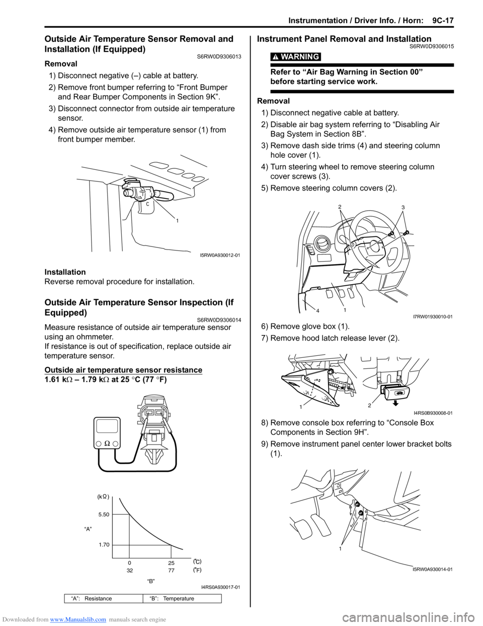
4) Remove outside air temperature sensor (1) from
front bumper member.
Installation
Reverse removal procedure for installation.
Outside Air Temperature Sensor Inspection (If
Equipped)
S6RW0D9306014
Measure resistance of outside air temperature sensor
using an ohmmeter.
If resistance is out of specification, replace outside air
temperature sensor.
Outside air temperature sensor resistance
1.61 kΩ – 1.79 kΩ at 25 °C (77 °F)
Instrument Panel Removal and InstallationS6RW0D9306015
WARNING!
Refer to “Air Bag Warning in Section 00”
before starting service work.
Removal
1) Disconnect negative cable at battery.
2) Disable air bag system referring to “Disabling Air
Bag System in Section 8B”.
3) Remove dash side trims (4) and steering column
hole cover (1).
4) Turn steering wheel to remove steering column
cover screws (3).
5) Remove steering column covers (2).
6) Remove glove box (1).
7) Remove hood latch release lever (2).
8) Remove console box referring to “Console Box
Components in Section 9H”.
9) Remove instrument panel center lower bracket bolts
(1).
“A”: Resistance “B”: Temperature
1
I5RW0A930012-01
“B” “A”5.50
1.70
0
3225
77
F
I4RS0A930017-01
2
3
1
4I7RW01930010-01
2
1I4RS0B930008-01
1
I5RW0A930014-01
Page 1370 of 1556
Downloaded from www.Manualslib.com manuals search engine 9C-18 Instrumentation / Driver Info. / Horn:
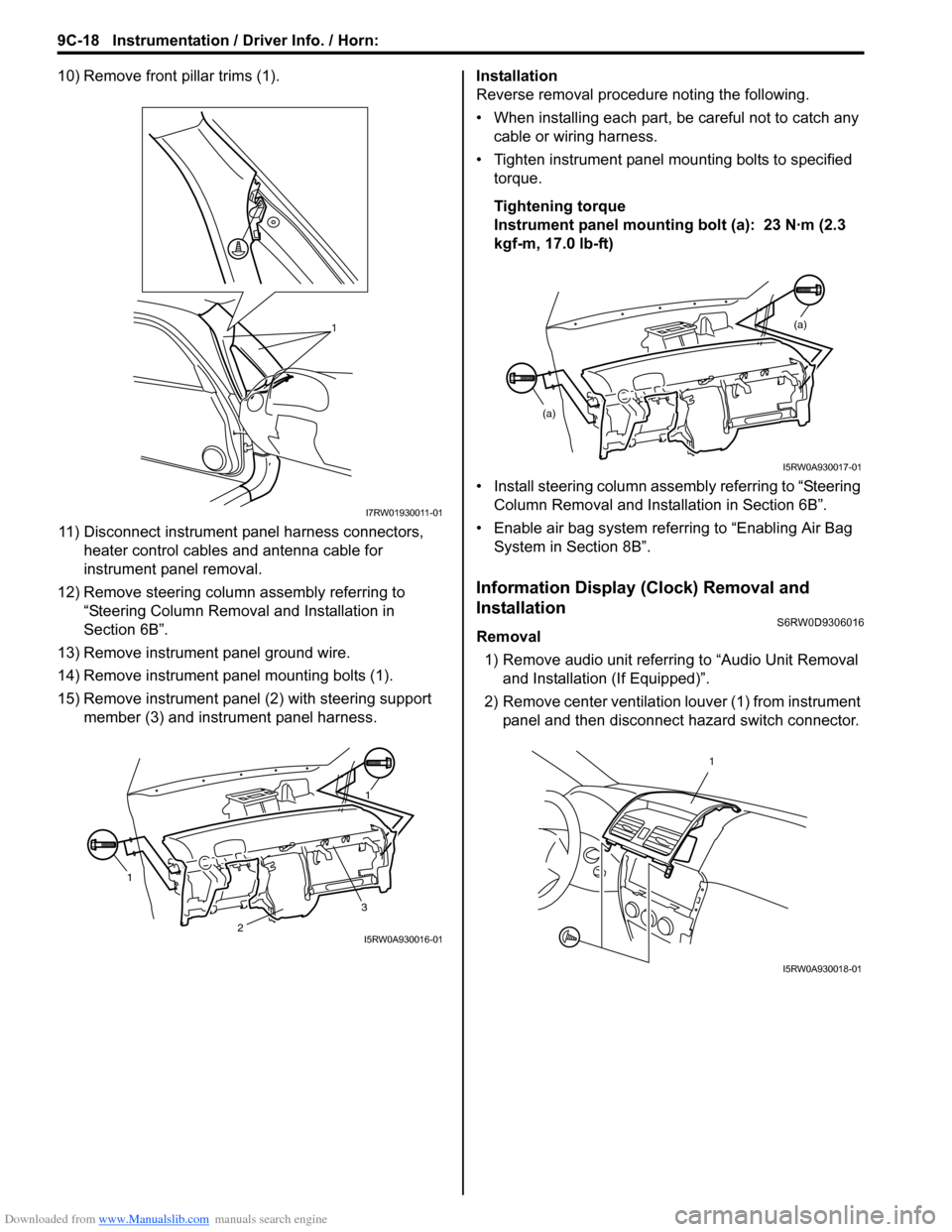
10) Remove front pillar trims (1).
11) Disconnect instrument panel harness connectors,
heater control cables and antenna cable for
instrument panel removal.
12) Remove steering column assembly referring to
“Steering Column Removal and Installation in
Section 6B”.
13) Remove instrument panel ground wire.
14) Remove instrument panel mounting bolts (1).
15) Remove instrument panel (2) with steering support
member (3) and instrument panel harness.Installation
Reverse removal procedure noting the following.
• When installing each part, be careful not to catch any
cable or wiring harness.
• Tighten instrument panel mounting bolts to specified
torque.
Tightening torque
Instrument panel mounting bolt (a): 23 N·m (2.3
kgf-m, 17.0 lb-ft)
• Install steering column assembly referring to “Steering
Column Removal and Installation in Section 6B”.
• Enable air bag system referring to “Enabling Air Bag
System in Section 8B”.
Information Display (Clock) Removal and
Installation
S6RW0D9306016
Removal
1) Remove audio unit referring to “Audio Unit Removal
and Installation (If Equipped)”.
2) Remove center ventilation louver (1) from instrument
panel and then disconnect hazard switch connector.
1
I7RW01930011-01
11
3
2I5RW0A930016-01
(a)
(a)
I5RW0A930017-01
1
I5RW0A930018-01
Page 1373 of 1556
Downloaded from www.Manualslib.com manuals search engine Instrumentation / Driver Info. / Horn: 9C-21
Antenna Base Removal and InstallationS6RW0D9306023
Removal
1) Remove head lining referring to “Head Lining
Removal and Installation in Section 9H”.
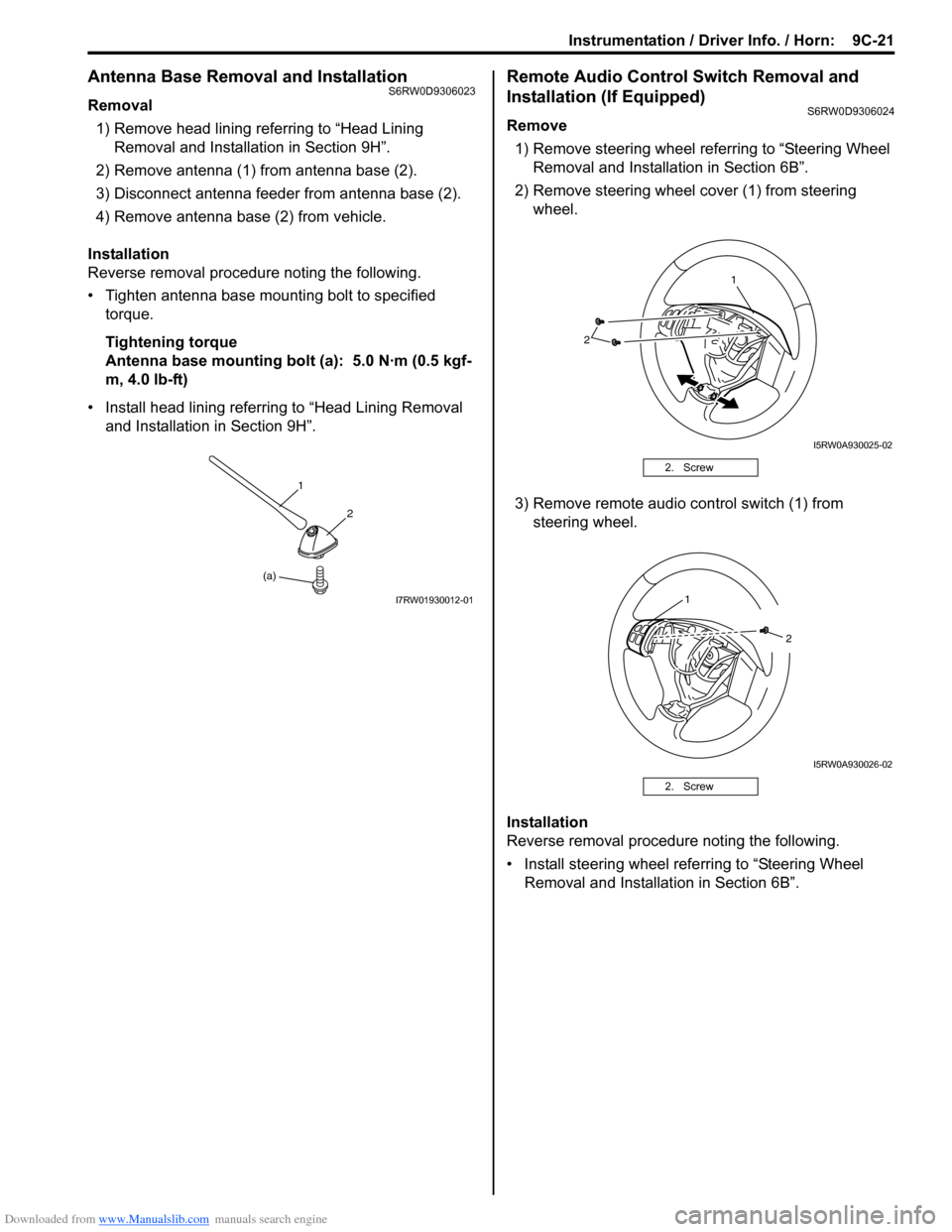
2) Remove antenna (1) from antenna base (2).
3) Disconnect antenna feeder from antenna base (2).
4) Remove antenna base (2) from vehicle.
Installation
Reverse removal procedure noting the following.
• Tighten antenna base mounting bolt to specified
torque.
Tightening torque
Antenna base mounting bolt (a): 5.0 N·m (0.5 kgf-
m, 4.0 lb-ft)
• Install head lining referring to “Head Lining Removal
and Installation in Section 9H”.
Remote Audio Control Switch Removal and
Installation (If Equipped)
S6RW0D9306024
Remove
1) Remove steering wheel referring to “Steering Wheel
Removal and Installation in Section 6B”.
2) Remove steering wheel cover (1) from steering
wheel.
3) Remove remote audio control switch (1) from
steering wheel.
Installation
Reverse removal procedure noting the following.
• Install steering wheel referring to “Steering Wheel
Removal and Installation in Section 6B”.
(a)1
2
I7RW01930012-01
2. Screw
2. Screw
2
1
I5RW0A930025-02
1
2
I5RW0A930026-02
Page 1382 of 1556
Downloaded from www.Manualslib.com manuals search engine 9D-8 Wipers / Washers:
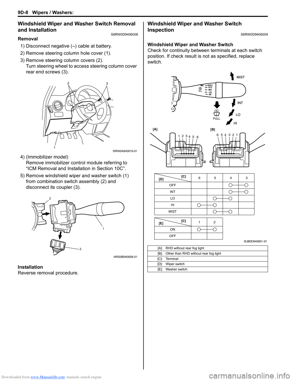
Windshield Wiper and Washer Switch Removal
and Installation
S6RW0D9406008
Removal
1) Disconnect negative (–) cable at battery.
2) Remove steering column hole cover (1).
3) Remove steering column covers (2).
Turn steering wheel to access steering column cover
rear end screws (3).
4) (Immobilizer model)
Remove immobilizer control module referring to
“ICM Removal and Installation in Section 10C”.
5) Remove windshield wiper and washer switch (1)
from combination switch assembly (2) and
disconnect its coupler (3).
Installation
Reverse removal procedure.
Windshield Wiper and Washer Switch
Inspection
S6RW0D9406009
Windshield Wiper and Washer Switch
Check for continuity between terminals at each switch
position. If check result is not as specified, replace
switch.
12
3I5RW0A940016-01
1 2
3
I4RS0B940008-01
[A]: RHD without rear fog light
[B]: Other than RHD without rear fog light
[C]: Terminal
[D]: Wiper switch
[E]: Washer switch
OFF
INT6543
MIST
OFF12
ONLO
HI
65432112
3
4
5
6 [A]
[B]
[C]
[D]
[E][C]
I5JB0D940001-01
Page 1407 of 1556
Downloaded from www.Manualslib.com manuals search engine Glass / Windows / Mirrors: 9E-22
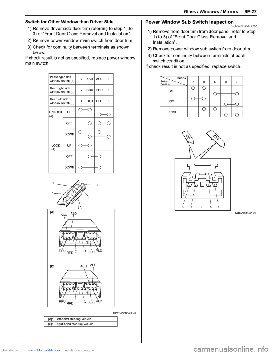
Switch for Other Window than Driver Side
1) Remove driver side door trim referring to step 1) to
3) of “Front Door Glass Removal and Installation”.
2) Remove power window main switch from door trim.
3) Check for continuity between terminals as shown
below.
If check result is not as specified, replace power window
main switch.Power Window Sub Switch InspectionS6RW0D9506022
1) Remove front door trim from door panel, refer to Step
1) to 3) of “Front Door Glass Removal and
Installation”.
2) Remove power window sub switch from door trim.
3) Check for continuity between terminals at each
switch condition.
If check result is not as specified, replace switch.
[A]: Left-hand steering vehicle
[B]: Right-hand steering vehicle
I5RW0A950036-02
I5JB0A950037-01
Page 1425 of 1556
Downloaded from www.Manualslib.com manuals search engine Security and Locks: 9F-14
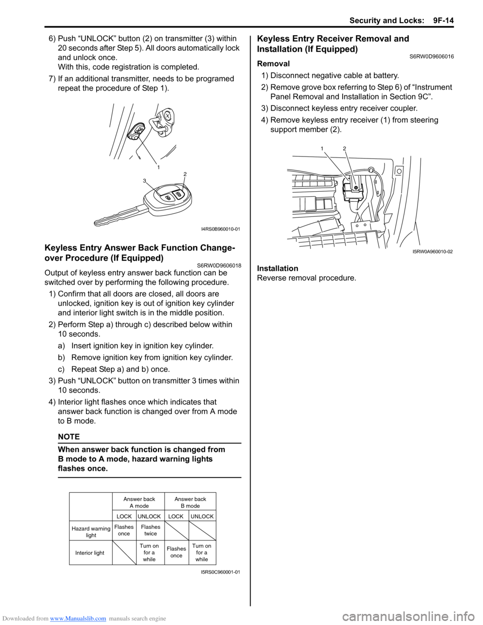
6) Push “UNLOCK” button (2) on transmitter (3) within
20 seconds after Step 5). All doors automatically lock
and unlock once.
With this, code registration is completed.
7) If an additional transmitter, needs to be programed
repeat the procedure of Step 1).
Keyless Entry Answer Back Function Change-
over Procedure (If Equipped)
S6RW0D9606018
Output of keyless entry answer back function can be
switched over by performing the following procedure.
1) Confirm that all doors are closed, all doors are
unlocked, ignition key is out of ignition key cylinder
and interior light switch is in the middle position.
2) Perform Step a) through c) described below within
10 seconds.
a) Insert ignition key in ignition key cylinder.
b) Remove ignition key from ignition key cylinder.
c) Repeat Step a) and b) once.
3) Push “UNLOCK” button on transmitter 3 times within
10 seconds.
4) Interior light flashes once which indicates that
answer back function is changed over from A mode
to B mode.
NOTE
When answer back function is changed from
B mode to A mode, hazard warning lights
flashes once.
Keyless Entry Receiver Removal and
Installation (If Equipped)
S6RW0D9606016
Removal
1) Disconnect negative cable at battery.
2) Remove grove box referring to Step 6) of “Instrument
Panel Removal and Installation in Section 9C”.
3) Disconnect keyless entry receiver coupler.
4) Remove keyless entry receiver (1) from steering
support member (2).
Installation
Reverse removal procedure.
1
32
I4RS0B960010-01
Hazard warning
light
LOCK LOCKUNLOCK UNLOCK
Interior lightFlashes
onceFlashes
twice
Flashes
once Turn on
for a
whileTurn on
for a
while Answer back
A modeAnswer back
B mode
I5RS0C960001-01
12
I5RW0A960010-02
Page 1472 of 1556
Downloaded from www.Manualslib.com manuals search engine 10-ii Table of Contents
Immobilizer Indicator Light Remains ON after
Engine Start ..................................................10C-10
DTC P1614: Transponder Response Error .....10C-10
DTC P1615: Steering Lock Unit
Communication Error ....................................10C-11
DTC P1616: Unregistered Keyless Start
Control Module ..............................................10C-12
DTC P1618: Keyless Start Control Module
CAN Communication Error............................10C-13
DTC P1621: Immobilizer Communication
Line Error ......................................................10C-13
DTC P1622: EEPROM Reading / Writing
Error ..............................................................10C-14
DTC P1623: Unregistered Transponder .........10C-14
DTC P1625: Immobilizer Antenna Error..........10C-15
DTC P1636: Immobilizer Information
Registration Failure .......................................10C-15
DTC P1638: Immobilizer Information
Mismatched ...................................................10C-16
Inspection of ICM and Its Circuit .....................10C-17
Repair Instructions ..........................................10C-19
ICM Removal and Installation .........................10C-19
Registration of the Ignition Key .......................10C-19
Procedure after ECM Replacement ................10C-19
Special Tools and Equipment .........................10C-20
Special Tool ....................................................10C-20
Keyless Start System .............................10E-1
General Description ........................................... 10E-1
Keyless Start System Description ..................... 10E-1
Parts and Functions .......................................... 10E-2
Keyless Engine Start Function .......................... 10E-3
Door Lock Function of Keyless Start System .... 10E-4
Operation Area of Remote Controller................ 10E-5
Alarm Function .................................................. 10E-6
CAN Communication System Description......... 10E-6
Schematic and Routing Diagram ...................... 10E-7
Keyless Start System Electric Wiring Circuit
Diagram .......................................................... 10E-7
Diagnostic Information and Procedures .......... 10E-8
Precautions in Diagnosing Troubles ................. 10E-8
Self-Diagnosis Function .................................... 10E-8
Keyless Start System Diagnosis Introduction ... 10E-8
Keyless Start System Check ............................. 10E-9
Customer Questionnaire (Example) ................ 10E-10Key Indicator Light Check ............................... 10E-10
DTC Check...................................................... 10E-11
DTC Table ....................................................... 10E-12
DTC Clearance ............................................... 10E-12
Keyless Start System Symptom Diagnosis ..... 10E-13
Keyless Start System Operation Inspection .... 10E-14
Door Lock Operation (Keyless Start System) . 10E-14
Inspection of Keyless Start Control Module
and Its Circuits .............................................. 10E-14
No DTC Detection After Performing DTC
Check ............................................................ 10E-20
Key Indicator Light Circuit Check (Key
Indicator Light Doesn’t Light when Ignition
Knob Switch is Pushed) ................................ 10E-21
Keyless Start Control Module Power and
Ground Circuit Check .................................... 10E-23
DTC No. 11: Communication Error with
Steering Lock Unit ......................................... 10E-24
DTC No. 13 / No. 14: Release Signal Error
from Steering Lock Unit / Steering Lock Unit
Malfunction .................................................... 10E-25
DTC No. 21 / No. 22: Internal Error of Keyless
Start Control Module (EEPROM Reading
Error) / (EEPROM Writing Error) ................... 10E-25
DTC No. 31: Lost Communication with BCM .. 10E-26
DTC No. 33: Control Module Communication
Bus Off .......................................................... 10E-26
DTC No. 51 / No. 52 / No. 53: Driver Side /
Passenger Side / Rear End Door Request
Switch Failure................................................ 10E-26
Repair Instructions .......................................... 10E-27
Antennas and Request Switches Removal
and Installation .............................................. 10E-27
Front Door (Driver and Passenger Side), Rear
End Door Request Switch Inspection............ 10E-28
Steering Lock Unit Removal and Installation .. 10E-28
Steering Lock Unit Inspection ......................... 10E-28
Front Door Lock Switch Inspection ................. 10E-28
Keyless Start Control Module Removal and
Installation ..................................................... 10E-29
Remote Controller Inspection.......................... 10E-29
Replacement of Remote Controller Battery .... 10E-29
Registration Procedure for Remote Controller
ID Code ......................................................... 10E-30
Keyless Start Registration ............................... 10E-31