Page 1306 of 1556
Downloaded from www.Manualslib.com manuals search engine 9A-139 Wiring Systems:
K12112
102102
2
11
22
11
211
G248
G248
BLK
Tweeter (L)Front (L)
J142J148
Tweeter (R)Front (R)
J141
J147
BLK
YEL
BLK
Audio
G306
J/C
ILL cancel
switch
A
A
C
C
G306
J/C
C
C
Steering switch (Audio control switch)
19G26710 120
BLKGRNWHT/GRN
BLK
BLUPNK
BLUPNK
BLUPNK
BLUBLKBLKBLUPNKPNK
YEL/BLKYEL/RED
YEL/BLKYEL/RED
YEL/BLKYEL/RED
YEL/BLKYEL/BLKYEL/REDYEL/RED
S171
G346S61
Roof audio antenna
Contact
coil
Antenna amplifer
4 313 14
K153
G3481
BLK
BLK
K154
G3541
21
G343
L376
G341
L3742112
BLK/YEL
RED/BLU
RED/BLU
G309
J/C
B
B
141114
RHD
LHD
Without Auto cruise
With Auto cruise
Except Taiwan
Taiwan
Without ILL cancel switch
With ILL cancel switch A
E
G
H
A
B
G341
L374
G343
L376A
B
L379
J215
L380
J216A
B
L380
J216
L379
J215A
B
F
BCDEFGH
4
1CD3
2CD
4
1CD3
2CD
Y
"D-4"
I6RW0D910924-01
Page 1309 of 1556
Downloaded from www.Manualslib.com manuals search engine Wiring Systems: 9A-142
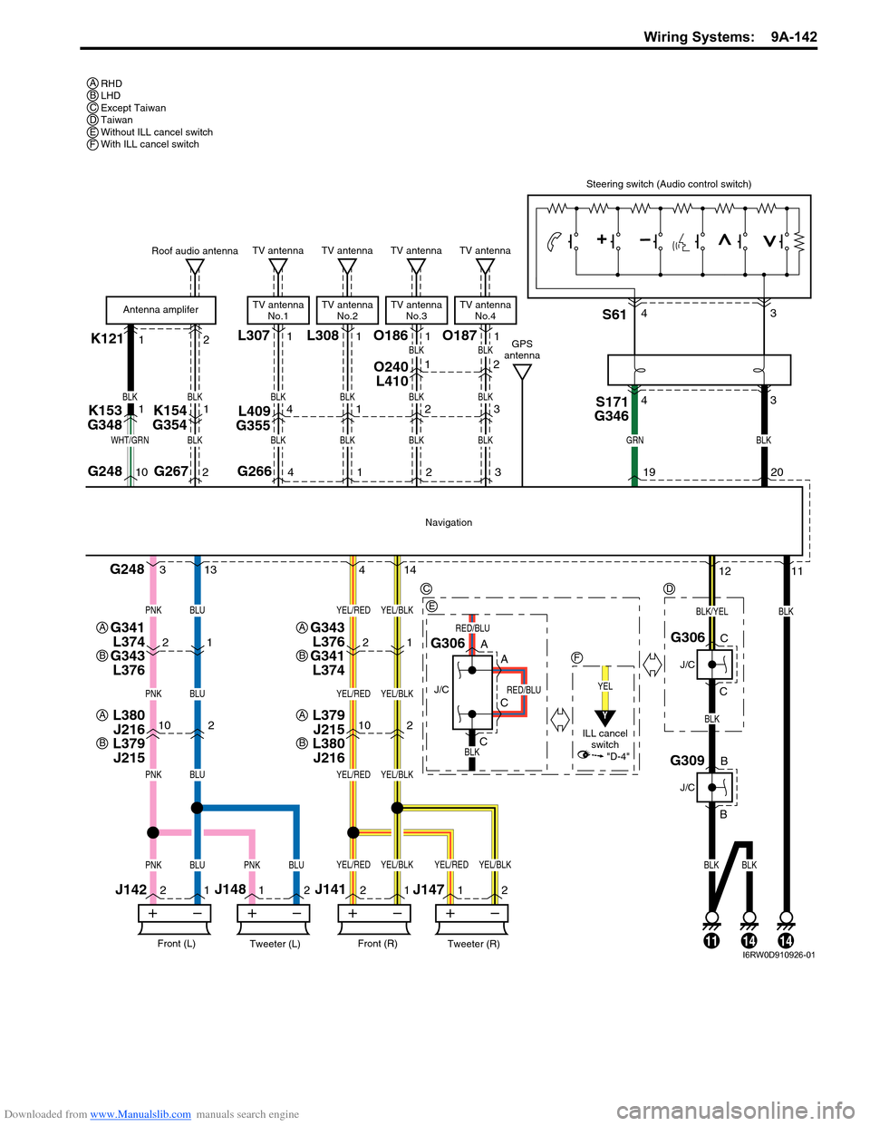
K121L30712
102102
2
11
22
11
211
G248
G248
BLK
Tweeter (L)Front (L)
J142J148
Tweeter (R)Front (R)
J141
J147
BLK
BLK
Navigation
G306
J/C
A
A
C
C
G306
J/C
C
C
Steering switch (Audio control switch)
19G26710 220
BLKGRNWHT/GRN
BLK
BLUPNK
BLUPNK
BLUPNK
BLUBLKBLKBLUPNKPNK
YEL/BLKYEL/RED
YEL/BLKYEL/RED
YEL/BLKYEL/RED
YEL/BLKYEL/BLKYEL/REDYEL/RED
S171
G346S61
Roof audio antenna
Antenna amplifer
4 313 14
K153
G3481
BLK
BLK
K154
G35411
G2664
TV antenna
TV antenna
No.1
BLK
BLK
L409
G3554
O240
L4101
21
G343
L376
G341
L3742112
BLK/YEL
RED/BLU
RED/BLU
G309
J/C
B
B
141114
RHD
LHD
Except Taiwan
Taiwan
Without ILL cancel switch
With ILL cancel switch A
C
E
F
A
B
G341
L374
G343
L376A
B
L379
J215
L380
J216A
B
L380
J216
L379
J215A
B
D
BCDEF
43 43
L3081
1
TV antenna
TV antenna
No.2
BLK
BLK1
O1861
2
TV antenna
TV antenna
No.3
BLK
BLK
BLK
2
2
O1871
3
TV antenna
TV antenna
No.4
BLK
BLK
BLK
3
GPS
antenna
YEL
ILL cancel
switch
Y
"D-4"
I6RW0D910926-01
Page 1325 of 1556
Downloaded from www.Manualslib.com manuals search engine Lighting Systems: 9B-6
Component Location
Lighting System Components LocationS6RW0D9203001
NOTE
Below figure shows left-hand steering vehicle. For right-hand steering vehicle, parts with (*) are
installed at the opposite side.
10
119
[D]25*30
21
27*26*29
31*20*
13
4
2
4
[A]
[B]
8
132
7 5
6
12
13
22
28*
15
16
[A]
17
18
19
15
16
17
18 [C]
14
23* 24*
I6RW0C920008-01
Page 1332 of 1556
Downloaded from www.Manualslib.com manuals search engine 9B-13 Lighting Systems:
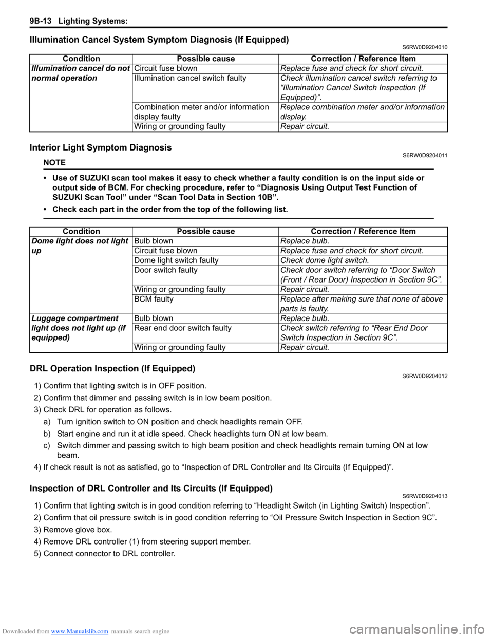
Illumination Cancel System Symptom Diagnosis (If Equipped)S6RW0D9204010
Interior Light Symptom DiagnosisS6RW0D9204011
NOTE
• Use of SUZUKI scan tool makes it easy to check whether a faulty condition is on the input side or
output side of BCM. For checking procedure, refer to “Diagnosis Using Output Test Function of
SUZUKI Scan Tool” under “Scan Tool Data in Section 10B”.
• Check each part in the order from the top of the following list.
DRL Operation Inspection (If Equipped)S6RW0D9204012
1) Confirm that lighting switch is in OFF position.
2) Confirm that dimmer and passing switch is in low beam position.
3) Check DRL for operation as follows.
a) Turn ignition switch to ON position and check headlights remain OFF.
b) Start engine and run it at idle speed. Check headlights turn ON at low beam.
c) Switch dimmer and passing switch to high beam position and check headlights remain turning ON at low
beam.
4) If check result is not as satisfied, go to “Inspection of DRL Controller and Its Circuits (If Equipped)”.
Inspection of DRL Controller and Its Circuits (If Equipped)S6RW0D9204013
1) Confirm that lighting switch is in good condition referring to “Headlight Switch (in Lighting Switch) Inspection”.
2) Confirm that oil pressure switch is in good condition referring to “Oil Pressure Switch Inspection in Section 9C”.
3) Remove glove box.
4) Remove DRL controller (1) from steering support member.
5) Connect connector to DRL controller.Condition Possible cause Correction / Reference Item
Illumination cancel do not
normal operationCircuit fuse blownReplace fuse and check for short circuit.
Illumination cancel switch faultyCheck illumination cancel switch referring to
“Illumination Cancel Switch Inspection (If
Equipped)”.
Combination meter and/or information
display faultyReplace combination meter and/or information
display.
Wiring or grounding faultyRepair circuit.
Condition Possible cause Correction / Reference Item
Dome light does not light
upBulb blownReplace bulb.
Circuit fuse blownReplace fuse and check for short circuit.
Dome light switch faultyCheck dome light switch.
Door switch faultyCheck door switch referring to “Door Switch
(Front / Rear Door) Inspection in Section 9C”.
Wiring or grounding faultyRepair circuit.
BCM faultyReplace after making sure that none of above
parts is faulty.
Luggage compartment
light does not light up (if
equipped)Bulb blownReplace bulb.
Rear end door switch faultyCheck switch referring to “Rear End Door
Switch Inspection in Section 9C”.
Wiring or grounding faultyRepair circuit.
Page 1334 of 1556
Downloaded from www.Manualslib.com manuals search engine 9B-15 Lighting Systems:
Auto-On Headlight Operation Inspection (If
Equipped)
S6RW0D9204021
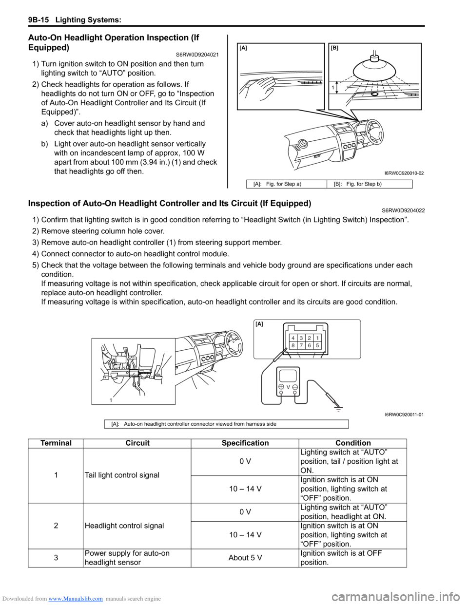
1) Turn ignition switch to ON position and then turn
lighting switch to “AUTO” position.
2) Check headlights for operation as follows. If
headlights do not turn ON or OFF, go to “Inspection
of Auto-On Headlight Controller and Its Circuit (If
Equipped)”.
a) Cover auto-on headlight sensor by hand and
check that headlights light up then.
b) Light over auto-on headlight sensor vertically
with on incandescent lamp of approx, 100 W
apart from about 100 mm (3.94 in.) (1) and check
that headlights go off then.
Inspection of Auto-On Headlight Controller and Its Circuit (If Equipped)S6RW0D9204022
1) Confirm that lighting switch is in good condition referring to “Headlight Switch (in Lighting Switch) Inspection”.
2) Remove steering column hole cover.
3) Remove auto-on headlight controller (1) from steering support member.
4) Connect connector to auto-on headlight control module.
5) Check that the voltage between the following terminals and vehicle body ground are specifications under each
condition.
If measuring voltage is not within specification, check applicable circuit for open or short. If circuits are normal,
replace auto-on headlight controller.
If measuring voltage is within specification, auto-on headlight controller and its circuits are good condition.
[A]: Fig. for Step a) [B]: Fig. for Step b)
[A] [B]
1
I6RW0C920010-02
1
4321
8765
V
[A]
I6RW0C920011-01
[A]: Auto-on headlight controller connector viewed from harness side
Terminal Circuit Specification Condition
1 Tail light control signal0 VLighting switch at “AUTO”
position, tail / position light at
ON.
10 – 14 VIgnition switch is at ON
position, lighting switch at
“OFF” position.
2 Headlight control signal0 VLighting switch at “AUTO”
position, headlight at ON.
10 – 14 VIgnition switch is at ON
position, lighting switch at
“OFF” position.
3Power supply for auto-on
headlight sensorAbout 5 VIgnition switch is at OFF
position.
Page 1340 of 1556
![SUZUKI SX4 2006 1.G Service Workshop Manual Downloaded from www.Manualslib.com manuals search engine 9B-21 Lighting Systems:
1
“H”“b”
“a”
2
10
[G] [F] [E]
7
8
9
6
7
5
10
11 8 9
7
6
5
A
A4
3
B B
A
A4
B B
“H”
“H” “H”
“H SUZUKI SX4 2006 1.G Service Workshop Manual Downloaded from www.Manualslib.com manuals search engine 9B-21 Lighting Systems:
1
“H”“b”
“a”
2
10
[G] [F] [E]
7
8
9
6
7
5
10
11 8 9
7
6
5
A
A4
3
B B
A
A4
B B
“H”
“H” “H”
“H](/manual-img/20/7612/w960_7612-1339.png)
Downloaded from www.Manualslib.com manuals search engine 9B-21 Lighting Systems:
1
“H”“b”
“a”
2
10
[G] [F] [E]
7
8
9
6
7
5
10
11 8 9
7
6
5
A
A4
3
B B
A
A4
B B
“H”
“H” “H”
“H” [C]
[D]
A
A4
B B
[A][B]
“H”“H”
XX XX XX
A
A4
B B
[A][B]
“H” “H” [I] [H]
[I] [H]
3
33
3
333
XX
[A][B]
[A][B]
6
5
8
9
I6RW0C920018-02
2. Headlight bulb 10. Headlight housing [D]: LH steering vehicle shown
3. Cut line (bounding line) 11. Headlight leveling actuator [E]: Without headlight leveling actuator
4. Hot spot X-X: Horizontal center line of headlight bulbs [F]: Headlight manual leveling model
5. Turning (for up adjustment) A-A: Vertical center line of left headlight bulb [G]: Headlight auto leveling model
6. Turning (for down adjustment) B-B: Vertical center line of right headlight bulb [H]: Other than discharge headlight model
7. Aiming gear (for right / left adjustment) [A]: Left headlight [I]: Discharge headlight model
8. Turning (for right adjustment) [B]: Right headlight
9. Turning (for left adjustment) [C]: RH steering vehicle shown
Page 1341 of 1556
Downloaded from www.Manualslib.com manuals search engine Lighting Systems: 9B-22
Headlight Switch (in Lighting Switch) Removal
and Installation
S6RW0D9206004
Removal
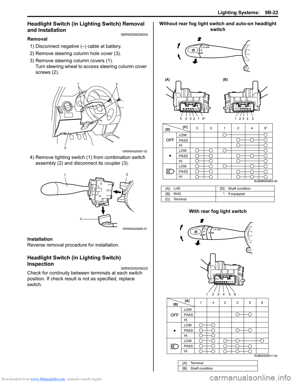
1) Disconnect negative (–) cable at battery.
2) Remove steering column hole cover (3).
3) Remove steering column covers (1).
Turn steering wheel to access steering column cover
screws (2).
4) Remove lighting switch (1) from combination switch
assembly (2) and disconnect its coupler (3).
Installation
Reverse removal procedure for installation.
Headlight Switch (in Lighting Switch)
Inspection
S6RW0D9206025
Check for continuity between terminals at each switch
position. If check result is not as specified, replace
switch.Without rear fog light switch and auto-on headlight
switch
With rear fog light switch
1
2
3
I5RW0A920007-02
2
1
3
I5RW0A920008-01
[A]: LHD [D]: Shaft condition
[B]: RHD *: If equipped
[C]: Terminal
[A]: Terminal
[B]: Shaft condition
[C]
[D]3 5
LOW
PASS
HI
LOW
PASS
HI LOW
PASS
HI
[A] [B]
1
6*2 3 4 5123 4 5
1246*
I6JB0B920003-02
[A]
[B]14 356
LOW
PASS
HI
LOW
PASS
HI LOW
PASS
HI
2
5 4 3 2 16
I5JB0D920011-04
Page 1349 of 1556
Downloaded from www.Manualslib.com manuals search engine Lighting Systems: 9B-30
Height Sensor and Its Circuit Inspection (If
Equipped)
S6RW0D9206028
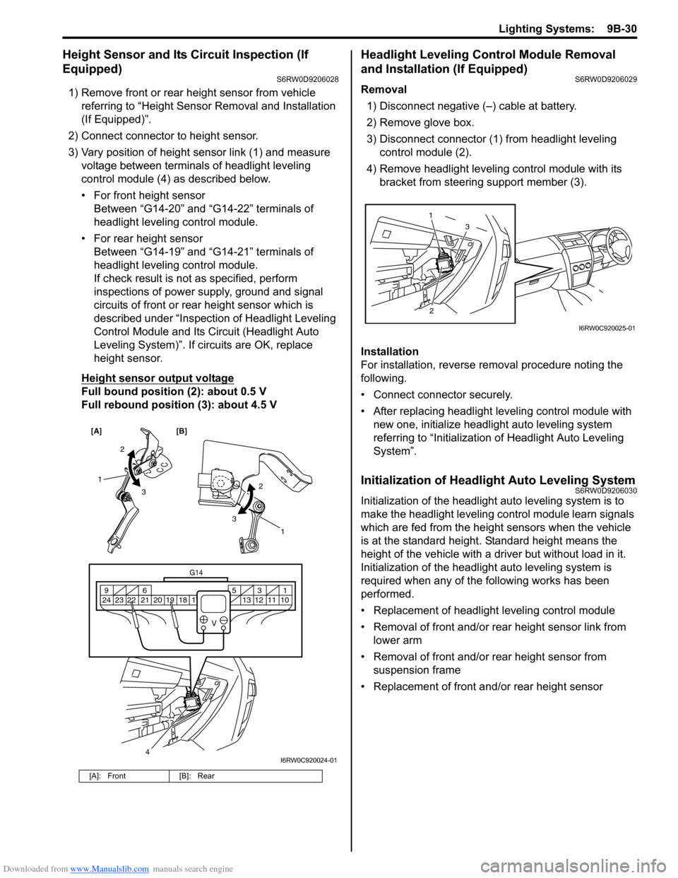
1) Remove front or rear height sensor from vehicle
referring to “Height Sensor Removal and Installation
(If Equipped)”.
2) Connect connector to height sensor.
3) Vary position of height sensor link (1) and measure
voltage between terminals of headlight leveling
control module (4) as described below.
• For front height sensor
Between “G14-20” and “G14-22” terminals of
headlight leveling control module.
• For rear height sensor
Between “G14-19” and “G14-21” terminals of
headlight leveling control module.
If check result is not as specified, perform
inspections of power supply, ground and signal
circuits of front or rear height sensor which is
described under “Inspection of Headlight Leveling
Control Module and Its Circuit (Headlight Auto
Leveling System)”. If circuits are OK, replace
height sensor.
Height sensor output voltage
Full bound position (2): about 0.5 V
Full rebound position (3): about 4.5 V
Headlight Leveling Control Module Removal
and Installation (If Equipped)
S6RW0D9206029
Removal
1) Disconnect negative (–) cable at battery.
2) Remove glove box.
3) Disconnect connector (1) from headlight leveling
control module (2).
4) Remove headlight leveling control module with its
bracket from steering support member (3).
Installation
For installation, reverse removal procedure noting the
following.
• Connect connector securely.
• After replacing headlight leveling control module with
new one, initialize headlight auto leveling system
referring to “Initialization of Headlight Auto Leveling
System”.
Initialization of Headlight Auto Leveling SystemS6RW0D9206030
Initialization of the headlight auto leveling system is to
make the headlight leveling control module learn signals
which are fed from the height sensors when the vehicle
is at the standard height. Standard height means the
height of the vehicle with a driver but without load in it.
Initialization of the headlight auto leveling system is
required when any of the following works has been
performed.
• Replacement of headlight leveling control module
• Removal of front and/or rear height sensor link from
lower arm
• Removal of front and/or rear height sensor from
suspension frame
• Replacement of front and/or rear height sensor
[A]: Front [B]: Rear
[A] [B]
4
G14
10 11 12 13 16 17 18 19 2031 5 6 9
21 22 23 24
V
2
3 1
2
3
1
I6RW0C920024-01
23 1
I6RW0C920025-01