Page 321 of 444
0-3
ABS SYSTEM
RODIUS 2007.07
4892-01
4892-01ABS
1. SPECIAL TOOLS AND EQUIPMENT
Page 322 of 444

0-4
RODIUS 2007.07
4892-01
ABS SYSTEM
2. GENERAL INFORMATION
The aim of the ABS is to mmaintain steerability and driving stability and to take the burden off
the driver. If the stopping distance is shorter on some road surfaces (carriageway conditions),
this is a gift of physics and not a development aim.
ABS is a device which senses that one or more of the wheels are locking up during braking. It
monitors the rotational speeds of the wheels and reduces hydraulic pressure to any wheel it
senses locking up. It is controlled by both mechanical and electronic components. When you
apply the brakes, the ABS will regulate the flow of brake fluid being delivered to the brake
calipers. By the use of electronic computers, the brakes rapidly alternate (at a rate of 30 times
per second) from full pressure to full release.
1) DRIVING PHYSICS
To give you a better understanding of the tasks and functions of ABS, we will first look at the
physics principles.
(1) The Stopping Distance
The stopping distance depends on the vehicle weight and initial speed when braking starts.
This also applies for vehicle with ABS, where ABS always tries to set an optimum brake force
on each wheel. As great forces are exerted between the tires and the carriageway when
braking, even with ABS the wheels may scream and rubber is left on the road. With an
ABS
skid mark one may be able to clearly recognize the tire profile. The skid mark of an ABS vehicle
does not however leave any hint of the speed of the vehicle in the case of an accident, as it can
only be clearly drawn at the start of braking.
(2) Brake Force on a Wheel
The maximum possible brake force on a wheel depends on the wheel load and the adhesion
coefficient between tire and carriageway. With a low adhesion coefficient the brake force, which
can be obtained is very low. You are bound to know the result already from driving on winte
r
roads. With a high adhesion coefficient on a dry road, the brake force, which can be obtained,
is considerably higher. The brake force, which can be obtained, can be calculated from below
formula:
Page 323 of 444
0-5
ABS SYSTEM
RODIUS 2007.07
4892-01
Maximum brake force ▶
FBmax = Vehicle Weight x Adhesion
coefficientmh
The braking process cannot be described
sufficiently accurately with the brake forces
calculated. The values calculated only apply
if the wheel is not locked. In the case of a
locking wheel, the static friction turns into
lower sliding friction, with the result that the
stopping distance is increased. This loss of
friction is termed “slip” in specialist
literature.
Slip ▶
The brake slip is the difference between the vehicle speed and the wheel circumference speed.
If the wheel locks, the slip is greatest, that is 100 %. If the wheel is running freely and unbraked,
the slip is the lowest, equal to 0 %. Slip can be calculated from the vehicle speed Vveh and the
wheel speed Vw. The equation for this is:
S = X 100 %
Vveh = 100 km/h, Vw = 70 km/h
S = X 100 %
The slip is 30 %.
Vveh - Vw
Vveh
100 - 70
100
Page 324 of 444

0-6
RODIUS 2007.07
4892-01
ABS SYSTEM
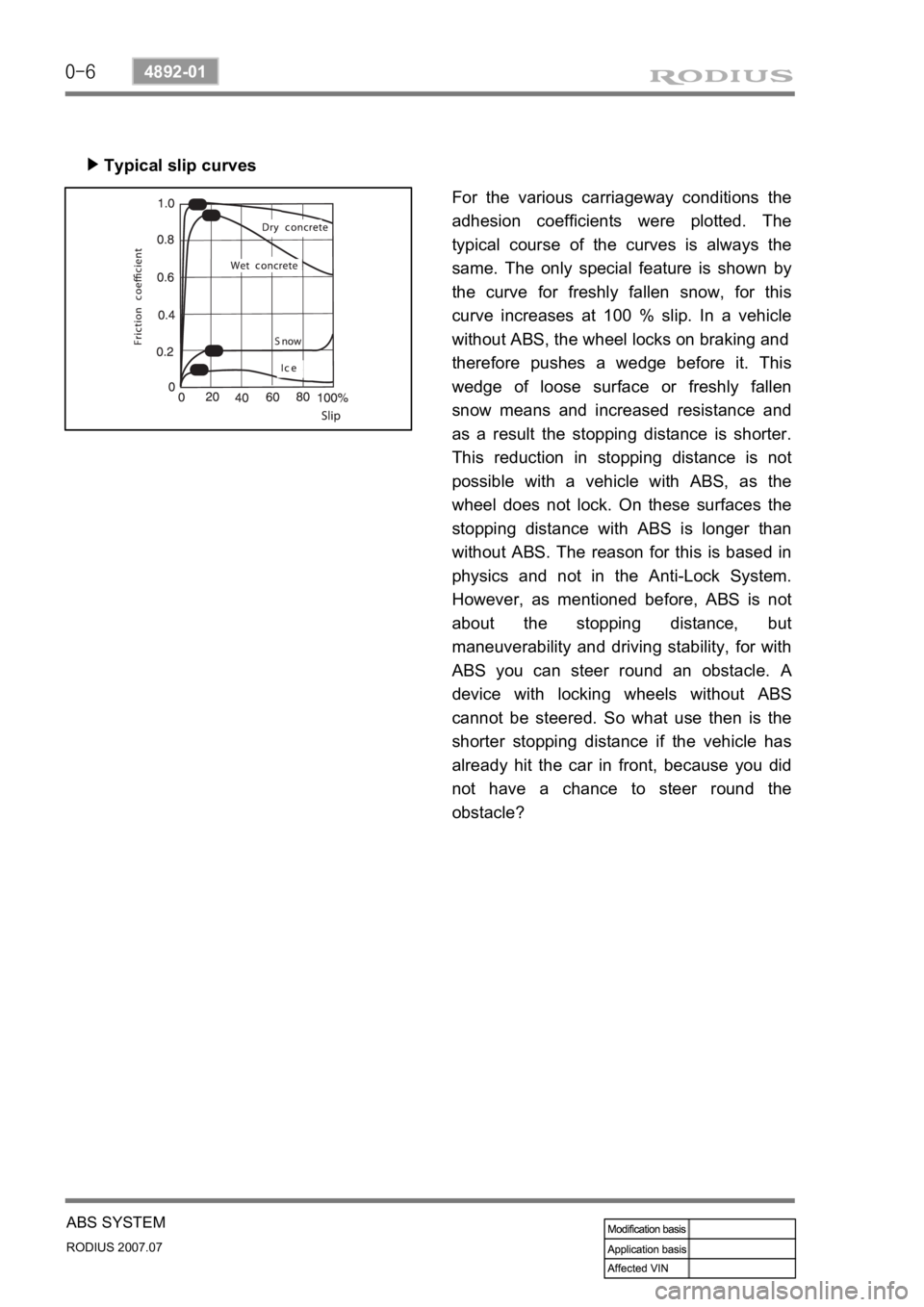
Typical slip curves ▶
For the various carriageway conditions the
adhesion coefficients were plotted. The
typical course of the curves is always the
same. The only special feature is shown by
the curve for freshly fallen snow, for this
curve increases at 100 % slip. In a vehicle
without ABS, the wheel locks on braking and
therefore pushes a wedge before it. This
wedge of loose surface or freshly fallen
snow means and increased resistance and
as a result the stopping distance is shorter.
This reduction in stopping distance is not
possible with a vehicle with ABS, as the
wheel does not lock. On these surfaces the
stopping distance with ABS is longer than
without ABS. The reason for this is based in
physics and not in the Anti-Lock System.
However, as mentioned before, ABS is not
about the stopping distance, but
maneuverability and driving stability, for with
ABS you can steer round an obstacle.
A
device with locking wheels without ABS
cannot be steered. So what use then is the
shorter stopping distance if the vehicle has
already hit the car in front, because you did
not have a chance to steer round the
obstacle?
Page 325 of 444
0-7
ABS SYSTEM
RODIUS 2007.07
4892-01
Kamm circle ▶
Before we go into the Kamm circle, you
should know that a tire offers a maximum o
f
100 % transmissibility. It is all the same fo
r
the tire whether we require 100 % in the
direction of braking or in the direction of the
acting lateral force, e.g. when driving round
curves. If we drive into a curve too fast and
the tire requires 100 % transmissibility as
cornering force, the tire cannot transmit any
additional brake force. In spite of the ABS
the car is carried out of the curve. The
relationship between brake force B and
cornering force S is shown very clearly in
the Kamm circle. If we put a vehicle wheel in
this circle, the relationship becomes even
clearer. In this relationship: as long as the
acting forces and the resulting force remain
within the circle, the vehicle is stable to
drive. If a force exceeds the circle, the
vehicle leaves the road.
Page 326 of 444
0-8
RODIUS 2007.07
4892-01
ABS SYSTEM
Brake force
When depressing the brake pedal the
brake force increases to the maximum,
then the brake force decreases until the
wheel locks.
Cornering force
The cornering force is a maximum when
the wheel is turning freely with zero slip.
When braking the cornering force falls to
zero if the wheel locks (slip 100 %).
ABS operating range
The operating range starts just before the
maximum brake force and ends in
maximum, for the unstable range then
begins, in which no further modulation is
possible. The ABS controls the regulation
of the brake pressure so that the brake
force only becomes great enough for a
sufficient proportion of cornering force to
remain. With ABS we remain in the
Kamm circle as long as the car is driving
sensibly. We will leave driving physics
with these statements and turn to the
braking systems with and without ABS. -
-
- Brake and cornering force ▶
Page 327 of 444

0-9
ABS SYSTEM
RODIUS 2007.07
4892-01
(3) Basic ABS Controls
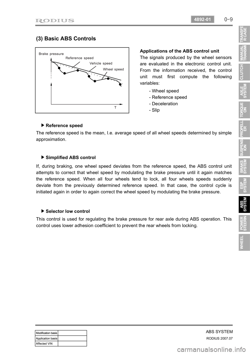
Applications of the ABS control unit
The signals produced by the wheel sensors
are evaluated in the electronic control unit.
From the information received, the control
unit must first compute the following
variables:
- Wheel speed
- Reference speed
- Deceleration
- Slip
Reference speed ▶
The reference speed is the mean, I.e. average speed of all wheel speeds determined by simple
approximation.
Simplified ABS control ▶
If, during braking, one wheel speed deviates from the reference speed, the ABS control unit
attempts to correct that wheel speed by modulating the brake pressure until it again matches
the reference speed. When all four wheels tend to lock, all four wheels speeds suddenly
deviate from the previously determined reference speed. In that case, the control cycle is
initiated again in order to again correct the wheel speed by modulating the brake pressure.
Selector low control ▶
This control is used for regulating the brake pressure for rear axle during ABS operation. This
control uses lower adhesion coefficient to prevent the rear wheels from locking.
Page 328 of 444

0-10
RODIUS 2007.07
4892-01
ABS SYSTEM
3. ON-VEHICLE SERVICE
(1) Electronic system service precautions
Take care to avoid electronic brake control module (HECU) circuit overloading. In testing for
opens or shorts, do not ground or apply voltage to any circuit unless instructed to do so by the
diagnostic procedure. Test circuits only with a high-impedance multi-meter. Never remove o
r
apply power to any control module with the ignition switch in the ON position. Always turn the
ignition to the OFF position before removing or connecting battery cables, fuses or connectors.
(2) General service precautions
Disconnect the HECU connector before performing any vehicle welding work using an electric
arc welder. Do not attempt to disassemble any component designated as nonserviceable. The
hydraulic modulator and the HECU can be seperated. (There is however no access to repai
r
the each components.)
(3) Bleeding system
Replacement modulators are shipped already filled and bled. In normal procedures requiring
removal of the modulator, such as to replace the HECU, air will not enter the modulator, and
normal bleeding will be all that is needed.
If air enters the hydraulic modulator, or if an unfilled modulator is installed, use the brake
bleeding program in the scan tool to bleed the modulator. Manual bleeding of the hydraulic
modulator is not possible.
1) Service Precautions
Brake Fluid may irritate eyes and skin. In case of contact, take the following actions:
Eye contact - rinse thoroughly with water.
Skin contact - wash with soap and water.
Ingestion - consult a physician immediately. -
-
-
To help avoid personal injury due to poor braking. DO NOT Tap into the vehicle’s
brake system to operate a trailer brake system.
When fasteners are removed, always reinstall them at the same location from which they
were removed. If a fastener needs to be replaced, use the correct part number fastener
for is not available, a fastener of equal size and strength (or stronger) may be used.
Fasteners that are not reused, and those requiring thread-locking compound will be
called out. The correct torque values must be used when installing fasteners that require
them. If the above procedures are not followed, parts or system damage could result.