Page 290 of 444
0-3
SUSPENSION SYSTEM
RODIUS 2007.07
4111-01
4410-01SUSPENSION SYSTEM
1. FRONT SUSPENSION SPECIFICATION
Page 291 of 444
0-4
RODIUS 2007.07
4111-01
SUSPENSION SYSTEM
2. REAR SUSPENSION SPECIFICATION
Page 292 of 444
0-5
SUSPENSION SYSTEM
RODIUS 2007.07
4111-01
3. STRUCTURE OF SHOCK ABSORBER AND COIL SPRING
1) front coil spring
▶ Specification
Page 293 of 444
0-6
RODIUS 2007.07
4111-01
SUSPENSION SYSTEM
2) front shock absorber assembly
▶ Specification
Page 294 of 444
0-7
SUSPENSION SYSTEM
RODIUS 2007.07
4111-01
Marking Point
3) rear shock absorber
Keep the suitable distance when compressed and expanded.
Minimum length is 10 mm longer than the minimum length under compression. ·
·
▶Specification
Page 295 of 444
0-8
RODIUS 2007.07
4111-01
SUSPENSION SYSTEM
4) rear coil spring
Steel for high tensional spring is adapted.
Maintain more than 20 mm of freeplay when compressed.
Spring seat applied. ·
·
·
▶ Specification
Page 334 of 444

0-16
RODIUS 2007.07
4892-01
ABS SYSTEM
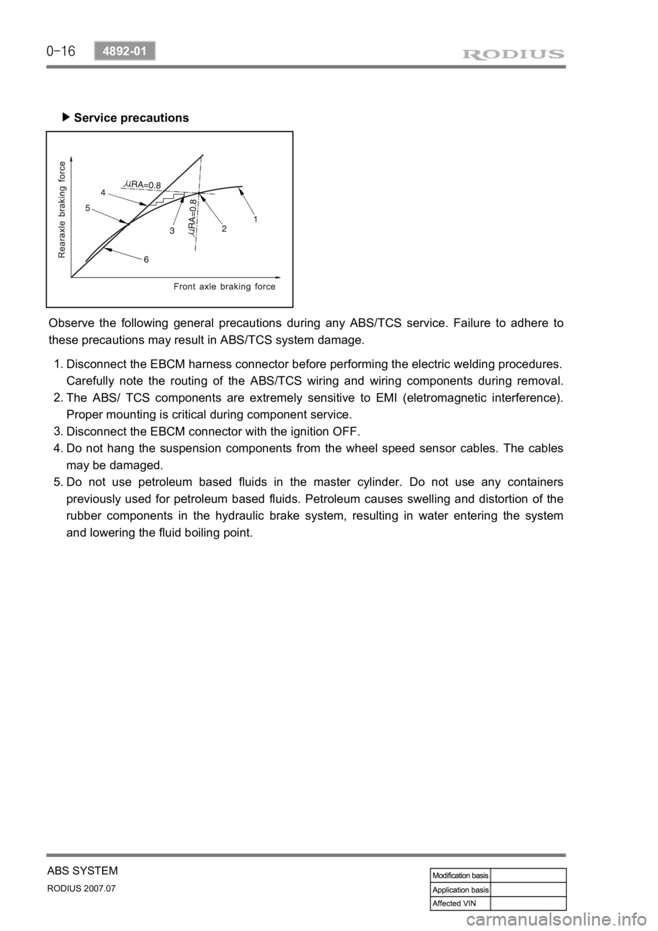
Service precautions ▶
Observe the following general precautions during any ABS/TCS service. Failure to adhere to
these precautions may result in ABS/TCS system damage.
Disconnect the EBCM harness connector before performing the electric welding procedures.
Carefully note the routing of the ABS/TCS wiring and wiring components during removal.
The ABS/ TCS components are extremely sensitive to EMI (eletromagnetic interference).
Proper mounting is critical during component service.
Disconnect the EBCM connector with the ignition OFF.
Do not hang the suspension components from the wheel speed sensor cables. The cables
may be damaged.
Do not use petroleum based fluids in the master cylinder. Do not use any containers
previously used for petroleum based fluids. Petroleum causes swelling and distortion of the
rubber components in the hydraulic brake system, resulting in water entering the system
and lowering the fluid boiling point. 1.
2.
3.
4.
5.
Page 352 of 444

0-8
RODIUS 2007.07
4710-09
WHEEL
3. WHEEL ALIGNMENT
The first responsibility of engineering is to design safe steering and suspension systems. Each
component must be strong enough to with stand and absorb extreme punishment.
Both the steering system and the front and the rear suspension must function geometrically
with the body mass.
The steering and suspension systems require that the front wheels self-return and that the tire
rolling effort and the road friction be held to a negligible force in order to allow the customer to
direct the vehicle with the least effort and the most comfort.
A complete wheel alignment check should include measurements of the rear toe and camber.
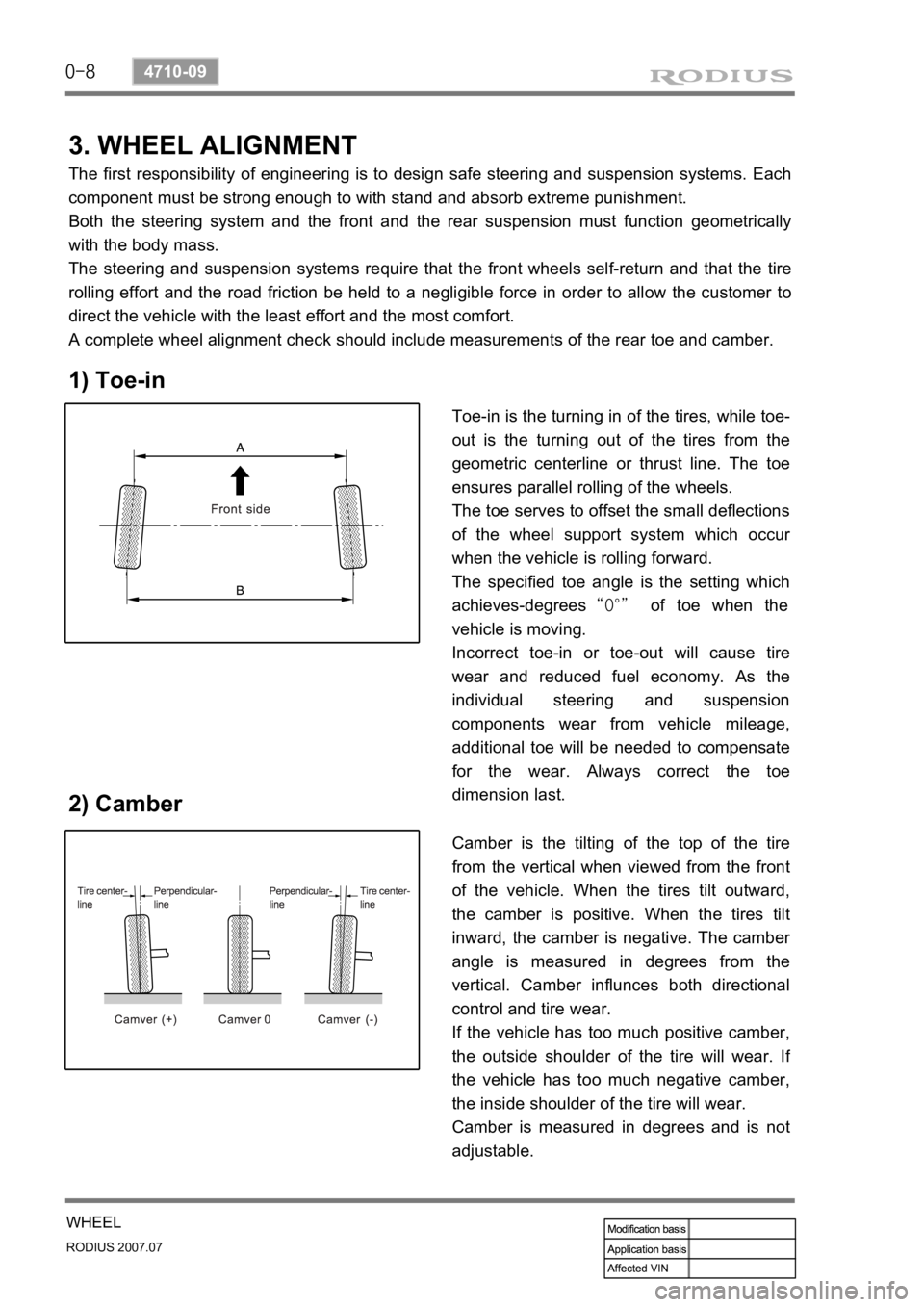
1) Toe-in
2) Camber
Toe-in is the turning in of the tires, while toe-
out is the turning out of the tires from the
geometric centerline or thrust line. The toe
ensures parallel rolling of the wheels.
The toe serves to offset the small deflections
of the wheel support system which occu
r
when the vehicle is rolling forward.
The specified toe angle is the setting which
achieves-degrees “0°” of toe when the
vehicle is moving.
Incorrect toe-in or toe-out will cause tire
wear and reduced fuel economy. As the
individual steering and suspension
components wear from vehicle mileage,
additional toe will be needed to compensate
for the wear. Always correct the toe
dimension last.
Camber is the tilting of the top of the tire
from the vertical when viewed from the front
of the vehicle. When the tires tilt outward,
the camber is positive. When the tires tilt
inward, the camber is negative. The cambe
r
angle is measured in degrees from the
vertical. Camber influnces both directional
control and tire wear.
If the vehicle has too much positive camber,
the outside shoulder of the tire will wear. I
f
the vehicle has too much negative camber,
the inside shoulder of the tire will wear.
Camber is measured in degrees and is not
adjustable.