Page 1333 of 2896

EC-164Revision: June 2006
DTC P0031, P0032 A/F SENSOR 1 HEATER
2007 Versa
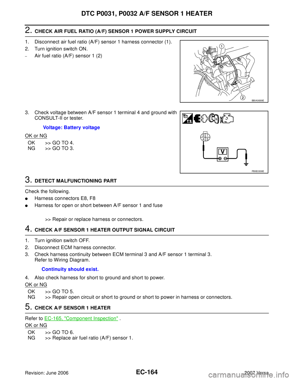
2. CHECK AIR FUEL RATIO (A/F) SENSOR 1 POWER SUPPLY CIRCUIT
1. Disconnect air fuel ratio (A/F) sensor 1 harness connector (1).
2. Turn ignition switch ON.
–Air fuel ratio (A/F) sensor 1 (2)
3. Check voltage between A/F sensor 1 terminal 4 and ground with
CONSULT-II or tester.
OK or NG
OK >> GO TO 4.
NG >> GO TO 3.
3. DETECT MALFUNCTIONING PART
Check the following.
�Harness connectors E8, F8
�Harness for open or short between A/F sensor 1 and fuse
>> Repair or replace harness or connectors.
4. CHECK A/F SENSOR 1 HEATER OUTPUT SIGNAL CIRCUIT
1. Turn ignition switch OFF.
2. Disconnect ECM harness connector.
3. Check harness continuity between ECM terminal 3 and A/F sensor 1 terminal 3.
Refer to Wiring Diagram.
4. Also check harness for short to ground and short to power.
OK or NG
OK >> GO TO 5.
NG >> Repair open circuit or short to ground or short to power in harness or connectors.
5. CHECK A/F SENSOR 1 HEATER
Refer to EC-165, "
Component Inspection" .
OK or NG
OK >> GO TO 6.
NG >> Replace air fuel ratio (A/F) sensor 1.
BBIA0699E
Voltage: Battery voltage
PBIB3308E
Continuity should exist.
Page 1337 of 2896
EC-168Revision: June 2006
DTC P0037, P0038 HO2S2 HEATER
2007 Versa
Wiring DiagramUBS00QCP
BBWA2628E
Page 1340 of 2896

DTC P0037, P0038 HO2S2 HEATER
EC-171
C
D
E
F
G
H
I
J
K
L
MA
EC
Revision: June 20062007 Versa
3. DETECT MALFUNCTIONING PART
Check the following.
�Harness connectors E8, F8
�Harness for open or short between heated oxygen sensor 2 and fuse
>> Repair open circuit or short to ground or short to power in harness or connectors.
4. CHECK HO2S2 OUTPUT SIGNAL CIRCUIT FOR OPEN AND SHORT
1. Turn ignition switch OFF.
2. Disconnect ECM harness connector.
3. Check harness continuity between ECM terminal 5 and HO2S2 terminal 3.
Refer to Wiring Diagram.
4. Also check harness for short to ground and short to power.
OK or NG
OK >> GO TO 5.
NG >> Repair open circuit or short to ground or short to power in harness or connectors.
5. CHECK HEATED OXYGEN SENSOR 2 HEATER
Refer to EC-172, "
Component Inspection" .
OK or NG
OK >> GO TO 6.
NG >> Replace heated oxygen sensor 2.
6. CHECK INTERMITTENT INCIDENT
Refer to EC-143, "
TROUBLE DIAGNOSIS FOR INTERMITTENT INCIDENT" .
>>INSPECTION END Continuity should exist.
Page 1343 of 2896
EC-174Revision: June 2006
DTC P0075 IVT CONTROL SOLENOID VALVE
2007 Versa
Wiring DiagramUBS00QCX
BBWA2627E
Page 1345 of 2896

EC-176Revision: June 2006
DTC P0075 IVT CONTROL SOLENOID VALVE
2007 Versa
Diagnostic ProcedureUBS00QCY
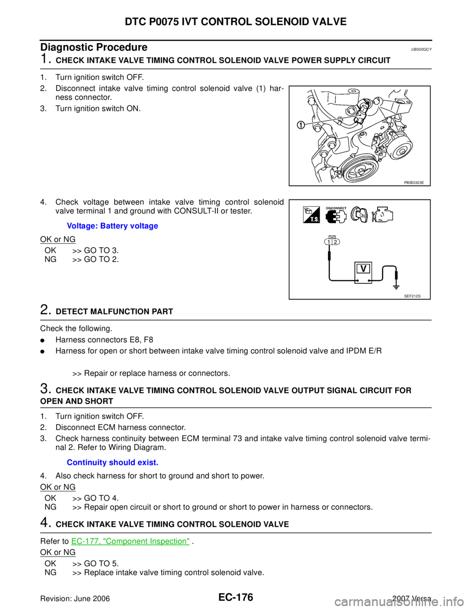
1. CHECK INTAKE VALVE TIMING CONTROL SOLENOID VALVE POWER SUPPLY CIRCUIT
1. Turn ignition switch OFF.
2. Disconnect intake valve timing control solenoid valve (1) har-
ness connector.
3. Turn ignition switch ON.
4. Check voltage between intake valve timing control solenoid
valve terminal 1 and ground with CONSULT-II or tester.
OK or NG
OK >> GO TO 3.
NG >> GO TO 2.
2. DETECT MALFUNCTION PART
Check the following.
�Harness connectors E8, F8
�Harness for open or short between intake valve timing control solenoid valve and IPDM E/R
>> Repair or replace harness or connectors.
3. CHECK INTAKE VALVE TIMING CONTROL SOLENOID VALVE OUTPUT SIGNAL CIRCUIT FOR
OPEN AND SHORT
1. Turn ignition switch OFF.
2. Disconnect ECM harness connector.
3. Check harness continuity between ECM terminal 73 and intake valve timing control solenoid valve termi-
nal 2. Refer to Wiring Diagram.
4. Also check harness for short to ground and short to power.
OK or NG
OK >> GO TO 4.
NG >> Repair open circuit or short to ground or short to power in harness or connectors.
4. CHECK INTAKE VALVE TIMING CONTROL SOLENOID VALVE
Refer to EC-177, "
Component Inspection" .
OK or NG
OK >> GO TO 5.
NG >> Replace intake valve timing control solenoid valve.
PBIB3323E
Voltage: Battery voltage
SEF 2 12 S
Continuity should exist.
Page 1350 of 2896
DTC P0101 MAF SENSOR
EC-181
C
D
E
F
G
H
I
J
K
L
MA
EC
Revision: June 20062007 Versa
Wiring DiagramUBS00QD6
BBWA2632E
Page 1353 of 2896

EC-184Revision: June 2006
DTC P0101 MAF SENSOR
2007 Versa
5. DETECT MALFUNCTIONING PART
Check the following.
�Harness connectors E8, F8
�Harness for open or short between mass air flow sensor and IPDM E/R
�Harness for open or short between mass air flow sensor and ECM
>> Repair open circuit or short to ground or short to power in harness or connectors.
6. CHECK MAF SENSOR GROUND CIRCUIT FOR OPEN AND SHORT
1. Turn ignition switch OFF.
2. Disconnect ECM harness connector.
3. Check harness continuity between MAF sensor terminal 3 and ECM terminal 52.
Refer to Wiring Diagram.
4. Also check harness for short to ground and short to power.
OK or NG
OK >> GO TO 7.
NG >> Repair open circuit or short to ground or short to power in harness or connectors.
7. CHECK MAF SENSOR INPUT SIGNAL CIRCUIT FOR OPEN AND SHORT
1. Check harness continuity between MAF sensor terminal 4 and ECM terminal 45.
Refer to Wiring Diagram.
2. Also check harness for short to ground and short to power.
OK or NG
OK >> GO TO 8.
NG >> Repair open circuit or short to ground or short or short to power in harness or connectors.
8. CHECK INTAKE AIR TEMPERATURE SENSOR
Refer to EC-217, "
Component Inspection" .
OK or NG
OK >> GO TO 9.
NG >> Replace intake air temperature sensor.
9. CHECK EVAP CONTROL SYSTEM PRESSURE SENSOR
Refer to EC-384, "
Component Inspection" .
OK or NG
OK >> GO TO 10.
NG >> Replace EVAP control system pressure sensor.
10. CHECK MASS AIR FLOW SENSOR
Refer to EC-185, "
Component Inspection" .
OK or NG
OK >> GO TO 11.
NG >> Replace mass air flow sensor.Continuity should exist.
Continuity should exist.
Page 1358 of 2896
DTC P0102, P0103 MAF SENSOR
EC-189
C
D
E
F
G
H
I
J
K
L
MA
EC
Revision: June 20062007 Versa
Wiring DiagramUBS00QDE
BBWA2632E