Page 1035 of 2896
CVT-138
DTC P0845 TRANSMISSION FLUID PRESSURE SENSOR B CIRCUIT (PRI
PRESSURE SENSOR)
Revision: June 20062007 Versa
Wiring Diagram — CVT — PRIPSUCS00625
BCWA0678E
Page 1040 of 2896

DTC P0868 SECONDARY PRESSURE DOWN
CVT-143
D
E
F
G
H
I
J
K
L
MA
B
CVT
Revision: June 20062007 Versa
Diagnostic ProcedureUCS0062C
1. CHECK INPUT SIGNAL
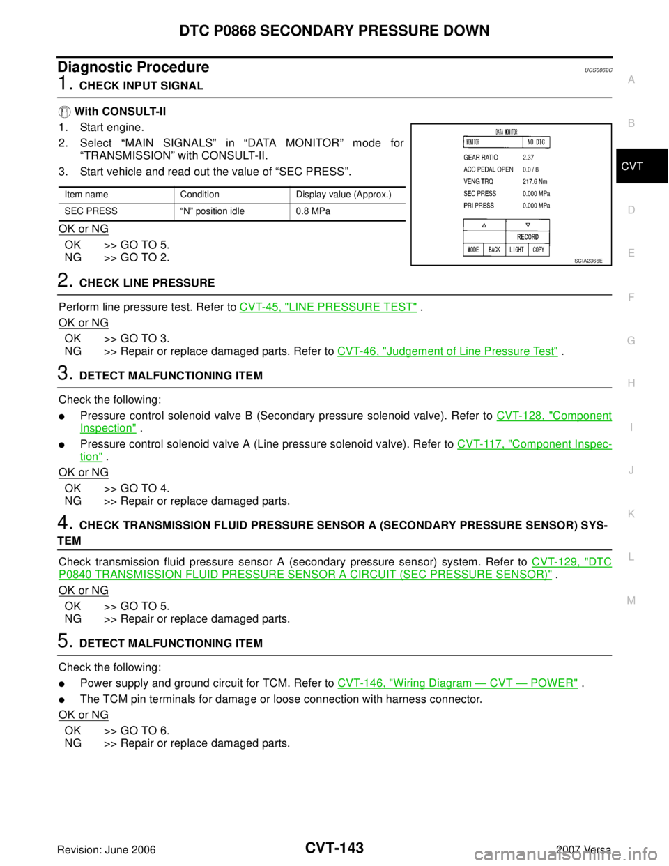
With CONSULT-II
1. Start engine.
2. Select “MAIN SIGNALS” in “DATA MONITOR” mode for
“TRANSMISSION” with CONSULT-II.
3. Start vehicle and read out the value of “SEC PRESS”.
OK or NG
OK >> GO TO 5.
NG >> GO TO 2.
2. CHECK LINE PRESSURE
Perform line pressure test. Refer to CVT-45, "
LINE PRESSURE TEST" .
OK or NG
OK >> GO TO 3.
NG >> Repair or replace damaged parts. Refer to CVT-46, "
Judgement of Line Pressure Test" .
3. DETECT MALFUNCTIONING ITEM
Check the following:
�Pressure control solenoid valve B (Secondary pressure solenoid valve). Refer to CVT-128, "Component
Inspection" .
�Pressure control solenoid valve A (Line pressure solenoid valve). Refer to CVT-117, "Component Inspec-
tion" .
OK or NG
OK >> GO TO 4.
NG >> Repair or replace damaged parts.
4. CHECK TRANSMISSION FLUID PRESSURE SENSOR A (SECONDARY PRESSURE SENSOR) SYS-
TEM
Check transmission fluid pressure sensor A (secondary pressure sensor) system. Refer to CVT-129, "
DTC
P0840 TRANSMISSION FLUID PRESSURE SENSOR A CIRCUIT (SEC PRESSURE SENSOR)" .
OK or NG
OK >> GO TO 5.
NG >> Repair or replace damaged parts.
5. DETECT MALFUNCTIONING ITEM
Check the following:
�Power supply and ground circuit for TCM. Refer to CVT-146, "Wiring Diagram — CVT — POWER" .
�The TCM pin terminals for damage or loose connection with harness connector.
OK or NG
OK >> GO TO 6.
NG >> Repair or replace damaged parts.
Item name Condition Display value (Approx.)
SEC PRESS “N” position idle 0.8 MPa
SCIA2366E
Page 1043 of 2896
CVT-146
DTC P1701 TRANSMISSION CONTROL MODULE (POWER SUPPLY)
Revision: June 20062007 Versa
Wiring Diagram — CVT — POWERUCS0062H
BCWA0679E
Page 1056 of 2896
DTC P1740 LOCK-UP SELECT SOLENOID VALVE CIRCUIT
CVT-159
D
E
F
G
H
I
J
K
L
MA
B
CVT
Revision: June 20062007 Versa
Wiring Diagram — CVT — L/USSVUCS0063A
BCWA0680E
Page 1062 of 2896
DTC P1777 STEP MOTOR - CIRCUIT
CVT-165
D
E
F
G
H
I
J
K
L
MA
B
CVT
Revision: June 20062007 Versa
Wiring Diagram — CVT — STMUCS0063N
BCWA0681E
Page 1068 of 2896
OVERDRIVE CONTROL SWITCH
CVT-171
D
E
F
G
H
I
J
K
L
MA
B
CVT
Revision: June 20062007 Versa
Wiring Diagram — CVT — ODSWUCS006KQ
BCWA0686E
Page 1073 of 2896
CVT-176
TROUBLE DIAGNOSIS FOR SYMPTOMS
Revision: June 20062007 Versa
TROUBLE DIAGNOSIS FOR SYMPTOMSPFP:00007
Wiring Diagram — CVT — NONDTCUCS00644
BCWA0682E
Page 1077 of 2896

CVT-180
TROUBLE DIAGNOSIS FOR SYMPTOMS
Revision: June 20062007 Versa
O/D OFF Indicator Lamp Does Not Come OnUCS00645
SYMPTOM:
O/D OFF indicator lamp does not come on for about 2 seconds when turning ignition switch ON.
DIAGNOSTIC PROCEDURE
1. CHECK CAN COMMUNICATION LINE
Perform the self-diagnosis check. Refer to CVT-60, "
SELF-DIAGNOSTIC RESULT MODE" .
Is any malfunction of the
“U1000 CAN COMM CIRCUIT” indicated in the results?
YES >> Check CAN communication line. Refer to CVT-68, "DTC U1000 CAN COMMUNICATION LINE" .
NO >> GO TO 2.
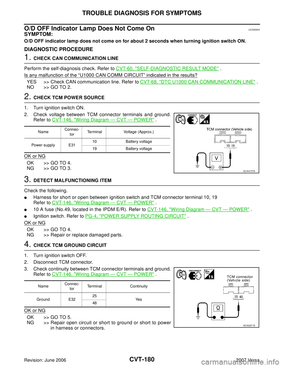
2. CHECK TCM POWER SOURCE
1. Turn ignition switch ON.
2. Check voltage between TCM connector terminals and ground.
Refer to CVT-146, "
Wiring Diagram — CVT — POWER" .
OK or NG
OK >> GO TO 4.
NG >> GO TO 3.
3. DETECT MALFUNCTIONING ITEM
Check the following.
�Harness for short or open between ignition switch and TCM connector terminal 10, 19
Refer to CVT-146, "
Wiring Diagram — CVT — POWER" .
�10 A fuse (No.49, located in the IPDM E/R). Refer to CVT-146, "Wiring Diagram — CVT — POWER" .
�Ignition switch. Refer to PG-4, "POWER SUPPLY ROUTING CIRCUIT" .
OK or NG
OK >> GO TO 4.
NG >> Repair or replace damaged parts.
4. CHECK TCM GROUND CIRCUIT
1. Turn ignition switch OFF.
2. Disconnect TCM connector.
3. Check continuity between TCM connector terminals and ground.
Refer to CVT-146, "
Wiring Diagram — CVT — POWER" .
OK or NG
OK >> GO TO 5.
NG >> Repair open circuit or short to ground or short to power
in harness or connectors.
NameConnec-
torTerminal Voltage (Approx.)
Power supply E3110 Battery voltage
19 Battery voltage
SCIA4737E
NameConnec-
torTerminal Continuity
Ground E3225
Ye s
48
SCIA2671E