Page 575 of 2896

BL-86
INTELLIGENT KEY SYSTEM
Revision: June 20062007 Versa
List of Operation Related Parts
Parts marked with × are the parts related to operation
REMOTE KEYLESS ENTRY FUNCTIONS
The Intelligent Key has the same functions as the remote keyless entry system. Therefore, it can be used in
the same manner as the keyfob by operating the door lock/unlock button.
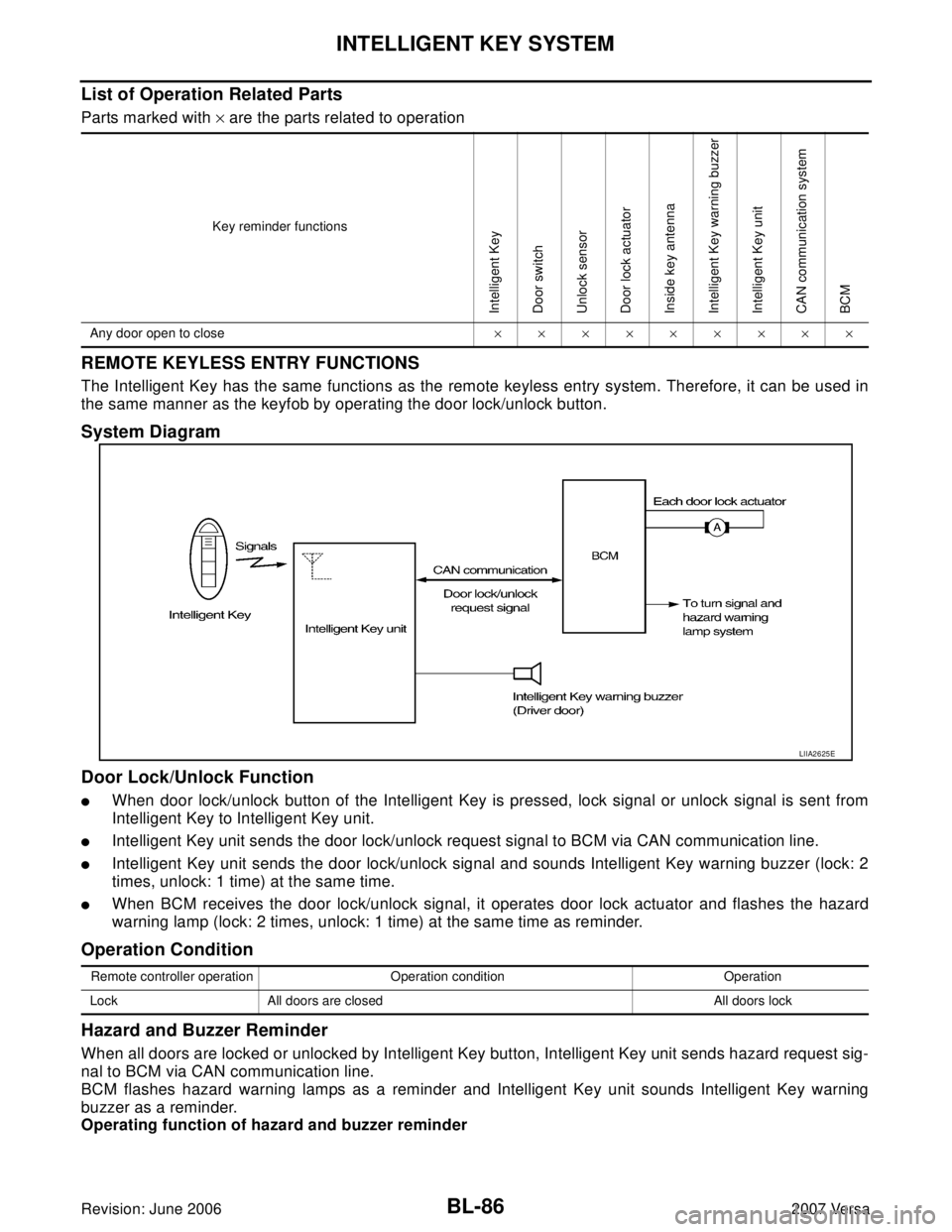
System Diagram
Door Lock/Unlock Function
�When door lock/unlock button of the Intelligent Key is pressed, lock signal or unlock signal is sent from
Intelligent Key to Intelligent Key unit.
�Intelligent Key unit sends the door lock/unlock request signal to BCM via CAN communication line.
�Intelligent Key unit sends the door lock/unlock signal and sounds Intelligent Key warning buzzer (lock: 2
times, unlock: 1 time) at the same time.
�When BCM receives the door lock/unlock signal, it operates door lock actuator and flashes the hazard
warning lamp (lock: 2 times, unlock: 1 time) at the same time as reminder.
Operation Condition
Hazard and Buzzer Reminder
When all doors are locked or unlocked by Intelligent Key button, Intelligent Key unit sends hazard request sig-
nal to BCM via CAN communication line.
BCM flashes hazard warning lamps as a reminder and Intelligent Key unit sounds Intelligent Key warning
buzzer as a reminder.
Operating function of hazard and buzzer reminder
Key reminder functions
Intelligent Key
Door switch
Unlock sensor
Door lock actuator
Inside key antenna
Intelligent Key warning buzzer
Intelligent Key unit
CAN communication system
BCM
Any door open to close×××××××××
LIIA2625E
Remote controller operation Operation condition Operation
Lock All doors are closed All doors lock
Page 585 of 2896
BL-96
INTELLIGENT KEY SYSTEM
Revision: June 20062007 Versa
Wiring Diagram — I/KEY —EIS00920
WIWA1964E
Page 666 of 2896
BACK DOOR LOCK
BL-177
C
D
E
F
G
H
J
K
L
MA
B
BL
Revision: June 20062007 Versa
Wiring Diagram — TLID —EIS009DM
WITHOUT INTELLIGENT KEY SYSTEM
LIWA0553E
Page 687 of 2896
BL-198
VEHICLE SECURITY (THEFT WARNING) SYSTEM
Revision: June 20062007 Versa
Wiring Diagram — VEHSEC —EIS009B1
WIWA1972E
Page 704 of 2896
NATS (NISSAN ANTI-THEFT SYSTEM)
BL-215
C
D
E
F
G
H
J
K
L
MA
B
BL
Revision: June 20062007 Versa
Wiring Diagram — NATS —EIS0093R
WIWA1975E
Page 820 of 2896

BRC-1
BRAKE CONTROL SYSTEM
F BRAKES
CONTENTS
C
D
E
G
H
I
J
K
L
M
SECTION BRC
A
B
BRC
Revision: June 20062007 VersaABS
PRECAUTIONS .......................................................... 2
Precautions for Supplemental Restraint System
(SRS) “AIR BAG” and “SEAT BELT PRE-TEN-
SIONER” .................................................................. 2
Precautions for Brake System .................................. 2
Precautions When Using CONSULT-II ..................... 2
CHECK POINTS FOR USING CONSULT-II ......... 2
Precautions for Brake Control .................................. 3
Precautions for CAN System ................................... 3
PREPARATION ........................................................... 4
Special Service Tools ............................................... 4
Commercial Service Tools ........................................ 4
SYSTEM DESCRIPTION ............................................ 5
System Components ................................................ 5
ABS Function ........................................................... 5
EBD Function ........................................................... 5
Fail-Safe Function .................................................... 6
ABS/EBD SYSTEM ............................................... 6
Hydraulic Circuit Diagram ........................................ 6
CAN COMMUNICATION ............................................ 7
System Description .................................................. 7
TROUBLE DIAGNOSIS .............................................. 8
How to Perform Trouble Diagnoses for Quick and
Accurate Repair ....................................................... 8
INTRODUCTION ................................................... 8
WORK FLOW ........................................................ 9
CLARIFY CONCERN .......................................... 10
EXAMPLE OF DIAGNOSIS SHEET ................... 10
Component Parts and Harness Connector Location ....11
Schematic .............................................................. 12
Wiring Diagram — ABS — ..................................... 13
Basic Inspection ..................................................... 17
BRAKE FLUID LEVEL, FLUID LEAK, AND
BRAKE PAD INSPECTION ................................. 17
POWER SYSTEM TERMINAL LOOSENESS AND BATTERY INSPECTION ............................. 17
ABS WARNING LAMP INSPECTION ................. 17
Warning Lamp and Indicator Timing ....................... 18
Control Unit Input/Output Signal Standard ............. 18
REFERENCE VALUE FROM CONSULT-II ......... 18
CONSULT-II Function (ABS) .................................. 20
CONSULT-II START PROCEDURE .................... 20
SELF-DIAGNOSIS .............................................. 20
DATA MONITOR ................................................. 22
ACTIVE TEST ..................................................... 24
TROUBLE DIAGNOSIS FOR SELF-DIAGNOSTIC
ITEMS ........................................................................ 25
Wheel Sensor System ............................................ 25
ABS Control Unit Inspection ................................... 26
Solenoid Valve System Inspection ......................... 27
Actuator Motor, Motor Relay, and Circuit Inspection ... 28
ABS Control Unit Power and Ground Systems
Inspection ............................................................... 29
CAN Communication System Inspection ................ 29
TROUBLE DIAGNOSES FOR SYMPTOMS ............ 30
ABS Works Frequently ........................................... 30
Unexpected Pedal Action ....................................... 31
Long Stopping Distance .......................................... 32
ABS Does Not Work ............................................... 32
Pedal Vibration or ABS Operation Noise ................ 32
WHEEL SENSORS ................................................... 33
Removal and Installation ........................................ 33
REMOVAL ........................................................... 33
INSTALLATION ................................................... 33
SENSOR ROTOR ..................................................... 35
Removal and Installation ........................................ 35
ACTUATOR AND ELECTRIC UNIT (ASSEMBLY) ... 36
Removal and Installation ........................................ 36
REMOVAL ........................................................... 36
INSTALLATION ................................................... 37
Page 825 of 2896
BRC-6
[ABS]
SYSTEM DESCRIPTION
Revision: June 20062007 Versa
Fail-Safe FunctionEFS006LF
CAUTION:
If the Fail-Safe function is activated, perform the Self Diagnosis for ABS system.
ABS/EBD SYSTEM
In case of an electrical malfunction with the ABS, the ABS warning lamp will turn on. In case of an electrical
malfunction with the EBD system, the brake warning lamp and the ABS warning lamp will turn on.
The system will revert to one of the following conditions of the Fail-Safe function.
1. For ABS malfunction, only the EBD is operative and the condition of the vehicle is the same condition of
vehicles without ABS system.
2. For EBD malfunction, the EBD and ABS become inoperative, and the condition of the vehicle is the same
as the condition of vehicles without ABS or EBD system.
Hydraulic Circuit DiagramEFS006LG
SFIA3082E
Page 832 of 2896
TROUBLE DIAGNOSIS
BRC-13
[ABS]
C
D
E
G
H
I
J
K
L
MA
B
BRC
Revision: June 20062007 Versa
Wiring Diagram — ABS —EFS006LL
WFWA0419E