2006 NISSAN PATROL ECU
[x] Cancel search: ECUPage 699 of 1226
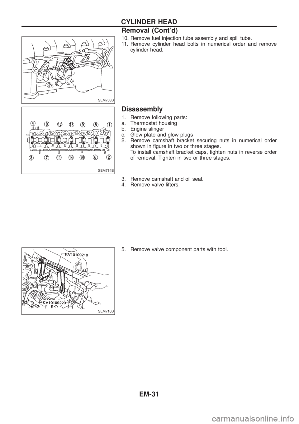
10. Remove fuel injection tube assembly and spill tube.
11. Remove cylinder head bolts in numerical order and remove
cylinder head.
Disassembly
1. Remove following parts:
a. Thermostat housing
b. Engine slinger
c. Glow plate and glow plugs
2. Remove camshaft bracket securing nuts in numerical order
shown in ®gure in two or three stages.
To install camshaft bracket caps, tighten nuts in reverse order
of removal. Tighten in two or three stages.
3. Remove camshaft and oil seal.
4. Remove valve lifters.
5. Remove valve component parts with tool.
SEM703B
SEM714B
SEM716B
CYLINDER HEAD
Removal (Cont'd)
EM-31
Page 723 of 1226
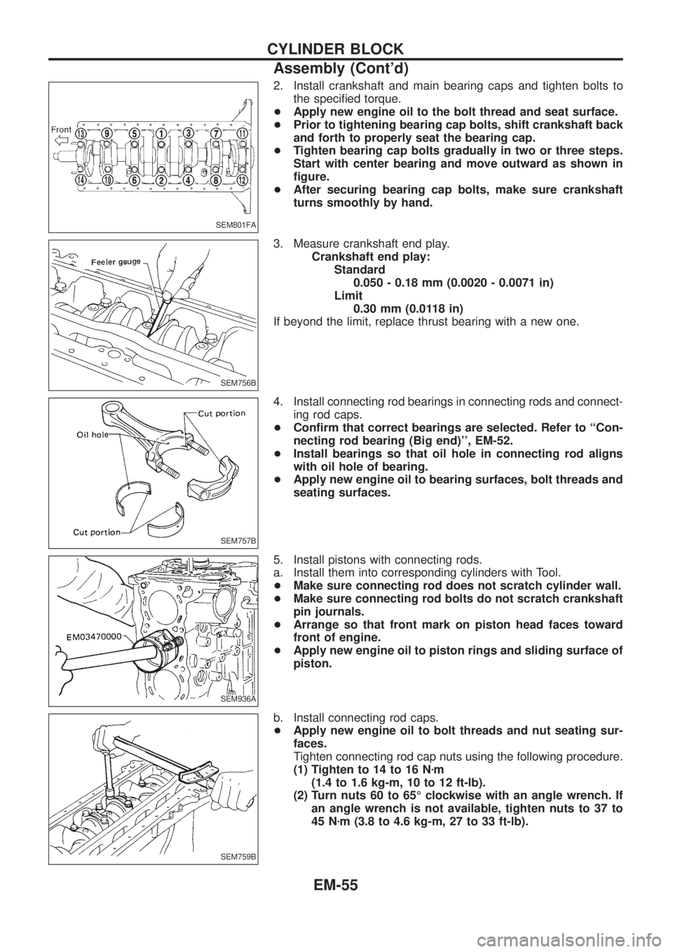
2. Install crankshaft and main bearing caps and tighten bolts to
the speci®ed torque.
+Apply new engine oil to the bolt thread and seat surface.
+Prior to tightening bearing cap bolts, shift crankshaft back
and forth to properly seat the bearing cap.
+Tighten bearing cap bolts gradually in two or three steps.
Start with center bearing and move outward as shown in
®gure.
+After securing bearing cap bolts, make sure crankshaft
turns smoothly by hand.
3. Measure crankshaft end play.
Crankshaft end play:
Standard
0.050 - 0.18 mm (0.0020 - 0.0071 in)
Limit
0.30 mm (0.0118 in)
If beyond the limit, replace thrust bearing with a new one.
4. Install connecting rod bearings in connecting rods and connect-
ing rod caps.
+Con®rm that correct bearings are selected. Refer to ``Con-
necting rod bearing (Big end)'', EM-52.
+Install bearings so that oil hole in connecting rod aligns
with oil hole of bearing.
+Apply new engine oil to bearing surfaces, bolt threads and
seating surfaces.
5. Install pistons with connecting rods.
a. Install them into corresponding cylinders with Tool.
+Make sure connecting rod does not scratch cylinder wall.
+Make sure connecting rod bolts do not scratch crankshaft
pin journals.
+Arrange so that front mark on piston head faces toward
front of engine.
+Apply new engine oil to piston rings and sliding surface of
piston.
b. Install connecting rod caps.
+Apply new engine oil to bolt threads and nut seating sur-
faces.
Tighten connecting rod cap nuts using the following procedure.
(1) Tighten to 14 to 16 Nzm
(1.4 to 1.6 kg-m, 10 to 12 ft-lb).
(2) Turn nuts 60 to 65É clockwise with an angle wrench. If
an angle wrench is not available, tighten nuts to 37 to
45 Nzm (3.8 to 4.6 kg-m, 27 to 33 ft-lb).
SEM801FA
SEM756B
SEM757B
SEM936A
SEM759B
CYLINDER BLOCK
Assembly (Cont'd)
EM-55
Page 799 of 1226
Voltage check method
1. Remove the blown fuse and disconnect all loads (i.e. SW1 open, relay disconnected and solenoid discon-
nected) powered through the fuse.
2. Turn the ignition key to the ON or START position. Verify battery voltage at the B
+side of the fuse ter-
minal (one lead on the B
+terminal side of the fuse block and one lead on a known good ground).
3. With SW1 open and the DMM leads across both fuse terminals, check for voltage.
voltage; short is between fuse block and SW1 (point A).
no voltage; short is further down the circuit than SW1.
4. With SW1 closed, relay and solenoid disconnected and the DMM leads across both fuse terminals, check
for voltage.
voltage; short is between SW1 and the relay (point B).
no voltage; short is further down the circuit than the relay.
5. With SW1 closed, relay contacts jumped with fused jumper wire check for voltage.
voltage; short is down the circuit of the relay or between the relay and the disconnected solenoid
(point C).
no voltage; retrace steps and check power to fuse block.
GROUND INSPECTION
Ground connections are very important to the proper operation of electrical and electronic circuits. Ground
connections are often exposed to moisture, dirt and other corrosive elements. The corrosion (rust) can become
an unwanted resistance. This unwanted resistance can change the way a circuit works.
Electronically controlled circuits are very sensitive to proper grounding. A loose or corroded ground can dras-
tically affect an electronically controlled circuit. A poor or corroded ground can easily affect the circuit. Even
when the ground connection looks clean, there can be a thin ®lm of rust on the surface.
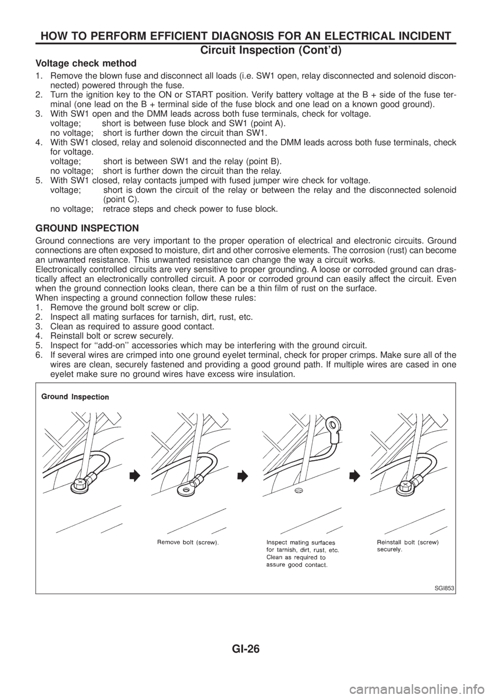
When inspecting a ground connection follow these rules:
1. Remove the ground bolt screw or clip.
2. Inspect all mating surfaces for tarnish, dirt, rust, etc.
3. Clean as required to assure good contact.
4. Reinstall bolt or screw securely.
5. Inspect for ``add-on'' accessories which may be interfering with the ground circuit.
6. If several wires are crimped into one ground eyelet terminal, check for proper crimps. Make sure all of the
wires are clean, securely fastened and providing a good ground path. If multiple wires are cased in one
eyelet make sure no ground wires have excess wire insulation.
SGI853
HOW TO PERFORM EFFICIENT DIAGNOSIS FOR AN ELECTRICAL INCIDENT
Circuit Inspection (Cont'd)
GI-26
Page 806 of 1226
Function and System Application
Diagnostic
test modeFunction ECCS Air bag ABS*
Work supportThis mode enables a technician to adjust
some devices faster and more accurately by
following the indications on CONSULT.xÐÐ
Self-diagnostic
resultsSelf-diagnostic results can be read and
erased quickly.xxx
Trouble diagnostic
recordCurrent self-diagnostic results and all trouble
diagnostic records previously stored can be
read.ÐxÐ
ECU discriminated
No.Classi®cation number of a replacement ECU
can be read to prevent an incorrect ECU
from being installed.ÐxÐ
Data monitor Input/Output data in the ECM can be read. x Ð x
Active testDiagnostic Test Mode in which CONSULT
drives some actuators apart from the ECMs
and also shifts some parameters in a speci-
®ed range.xÐx
ECM part number ECM part number can be read. x Ð x
Function testConducted by CONSULT instead of a tech-
nician to determine whether each system is
``OK'' or ``NG''.xÐÐ
x: Applicable
*: EE960 program card is not applicable to ABS. Use on board diagnostic system with ABS warning lamp until the next program card
will be introduced.
Lithium Battery Replacement
CONSULT contains a lithium battery. When replacing the battery obey the following:
WARNING:
Replace the lithium battery with SANYO Electric Co., Ltd., CR2032 only. Use of another battery may
present a risk of ®re or explosion. The battery may present a ®re or chemical burn hazard if mistreated.
Do not recharge, disassemble of dispose of in ®re.
Keep the battery out of reach of children and discard used battery conforming to the local regulations.
Checking Equipment
When ordering the below equipment, contact your NISSAN distributor.
Tool name Description
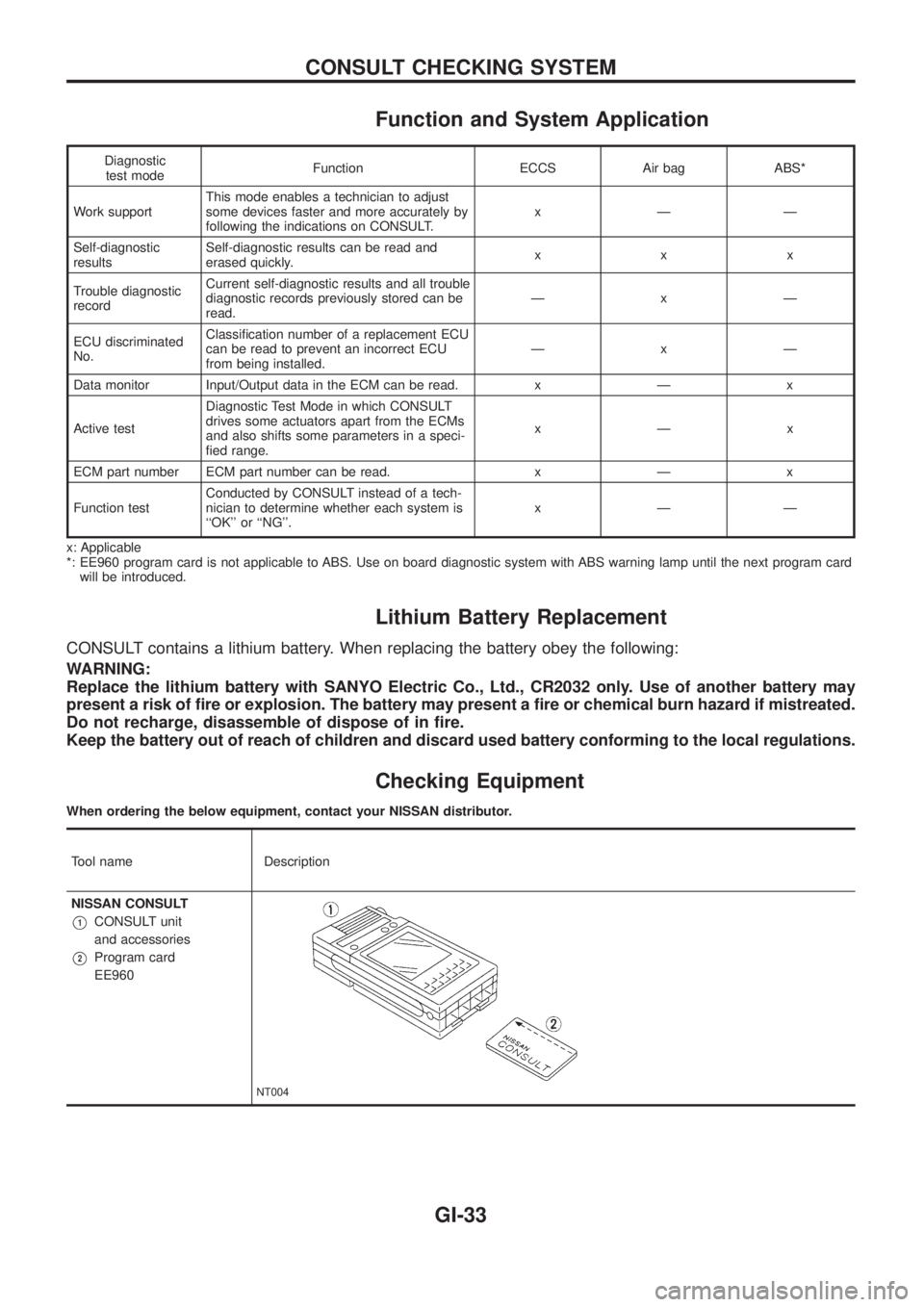
NISSAN CONSULT
V1CONSULT unit
and accessories
V2Program card
EE960
NT004
CONSULT CHECKING SYSTEM
GI-33
Page 814 of 1226
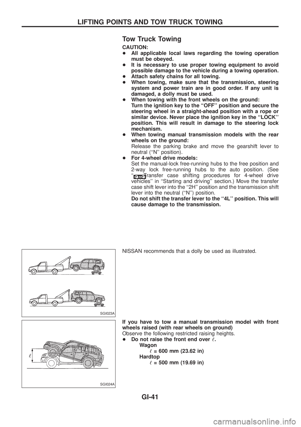
Tow Truck Towing
CAUTION:
+All applicable local laws regarding the towing operation
must be obeyed.
+It is necessary to use proper towing equipment to avoid
possible damage to the vehicle during a towing operation.
+Attach safety chains for all towing.
+When towing, make sure that the transmission, steering
system and power train are in good order. If any unit is
damaged, a dolly must be used.
+When towing with the front wheels on the ground:
Turn the ignition key to the ``OFF'' position and secure the
steering wheel in a straight-ahead position with a rope or
similar device. Never place the ignition key in the ``LOCK''
position. This will result in damage to the steering lock
mechanism.
+When towing manual transmission models with the rear
wheels on the ground:
Release the parking brake and move the gearshift lever to
neutral (``N'' position).
+For 4-wheel drive models:
Set the manual-lock free-running hubs to the free position and
2-way lock free-running hubs to the auto position. (See
``
Transfer case shifting procedures for 4-wheel drive
vehicles'' in ``Starting and driving'' section.) Move the transfer
case shift lever into the ``2H'' position and the transmission shift
lever into the neutral (``N'') position.
Do not shift the transfer lever to the ``4L'' position. This will
cause damage to the transmission.
NISSAN recommends that a dolly be used as illustrated.
If you have to tow a manual transmission model with front
wheels raised (with rear wheels on ground)
Observe the following restricted raising heights.
+Do not raise the front end over!.
Wagon
!= 600 mm (23.62 in)
Hardtop
!= 500 mm (19.69 in)
SGI023A
SGI024A
LIFTING POINTS AND TOW TRUCK TOWING
GI-41
Page 871 of 1226
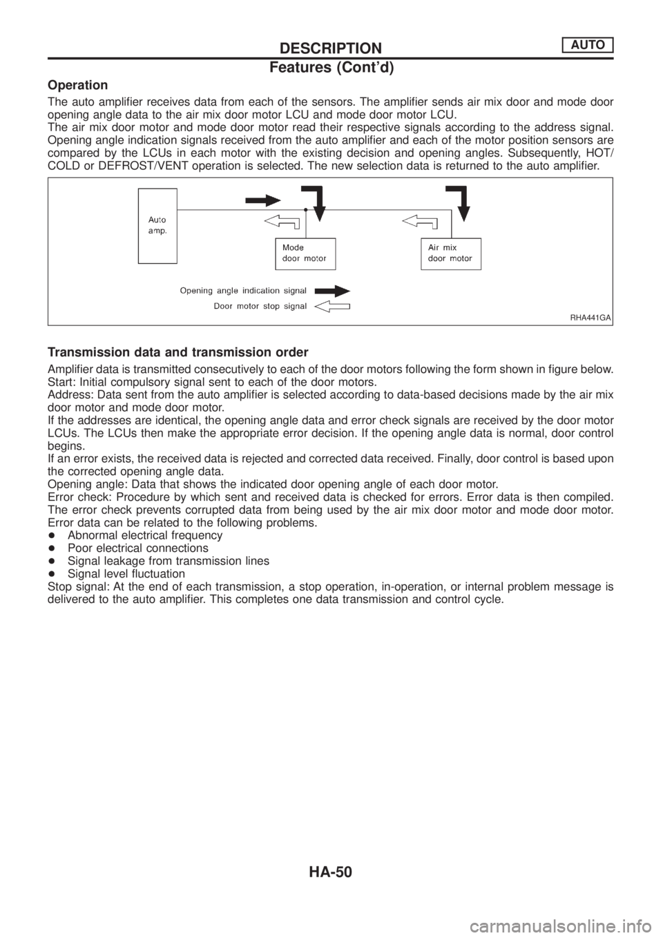
Operation
The auto ampli®er receives data from each of the sensors. The ampli®er sends air mix door and mode door
opening angle data to the air mix door motor LCU and mode door motor LCU.
The air mix door motor and mode door motor read their respective signals according to the address signal.
Opening angle indication signals received from the auto ampli®er and each of the motor position sensors are
compared by the LCUs in each motor with the existing decision and opening angles. Subsequently, HOT/
COLD or DEFROST/VENT operation is selected. The new selection data is returned to the auto ampli®er.
Transmission data and transmission order
Ampli®er data is transmitted consecutively to each of the door motors following the form shown in ®gure below.
Start: Initial compulsory signal sent to each of the door motors.
Address: Data sent from the auto ampli®er is selected according to data-based decisions made by the air mix
door motor and mode door motor.
If the addresses are identical, the opening angle data and error check signals are received by the door motor
LCUs. The LCUs then make the appropriate error decision. If the opening angle data is normal, door control
begins.
If an error exists, the received data is rejected and corrected data received. Finally, door control is based upon
the corrected opening angle data.
Opening angle: Data that shows the indicated door opening angle of each door motor.
Error check: Procedure by which sent and received data is checked for errors. Error data is then compiled.
The error check prevents corrupted data from being used by the air mix door motor and mode door motor.
Error data can be related to the following problems.
+Abnormal electrical frequency
+Poor electrical connections
+Signal leakage from transmission lines
+Signal level ¯uctuation
Stop signal: At the end of each transmission, a stop operation, in-operation, or internal problem message is
delivered to the auto ampli®er. This completes one data transmission and control cycle.
RHA441GA
DESCRIPTIONAUTO
Features (Cont'd)
HA-50
Page 902 of 1226
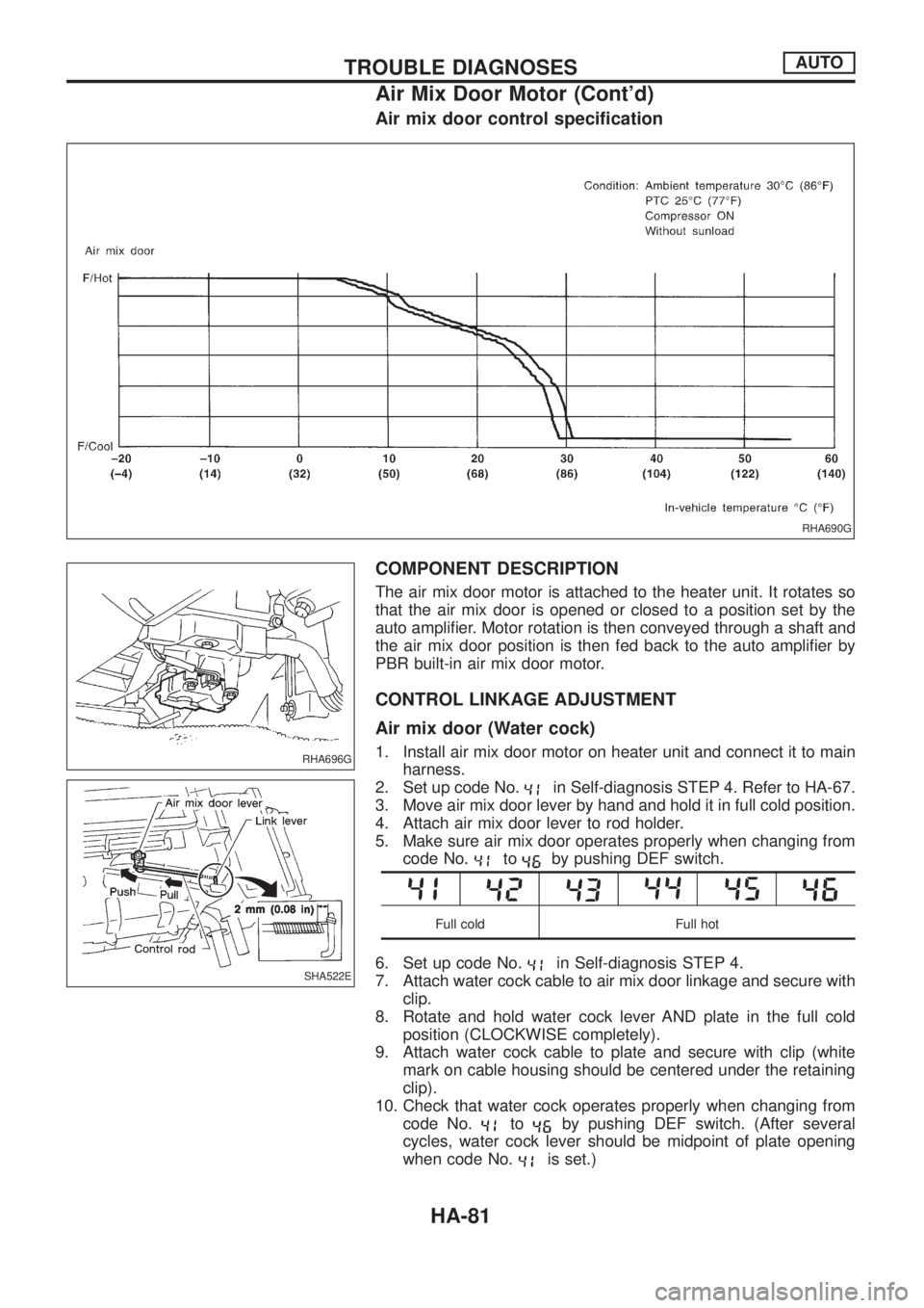
Air mix door control speci®cation
COMPONENT DESCRIPTION
The air mix door motor is attached to the heater unit. It rotates so
that the air mix door is opened or closed to a position set by the
auto ampli®er. Motor rotation is then conveyed through a shaft and
the air mix door position is then fed back to the auto ampli®er by
PBR built-in air mix door motor.
CONTROL LINKAGE ADJUSTMENT
Air mix door (Water cock)
1. Install air mix door motor on heater unit and connect it to main
harness.
2. Set up code No.
in Self-diagnosis STEP 4. Refer to HA-67.
3. Move air mix door lever by hand and hold it in full cold position.
4. Attach air mix door lever to rod holder.
5. Make sure air mix door operates properly when changing from
code No.
toby pushing DEF switch.
Full cold Full hot
6. Set up code No.in Self-diagnosis STEP 4.
7. Attach water cock cable to air mix door linkage and secure with
clip.
8. Rotate and hold water cock lever AND plate in the full cold
position (CLOCKWISE completely).
9. Attach water cock cable to plate and secure with clip (white
mark on cable housing should be centered under the retaining
clip).
10. Check that water cock operates properly when changing from
code No.
toby pushing DEF switch. (After several
cycles, water cock lever should be midpoint of plate opening
when code No.
is set.)
RHA690G
RHA696G
SHA522E
TROUBLE DIAGNOSESAUTO
Air Mix Door Motor (Cont'd)
HA-81
Page 941 of 1226
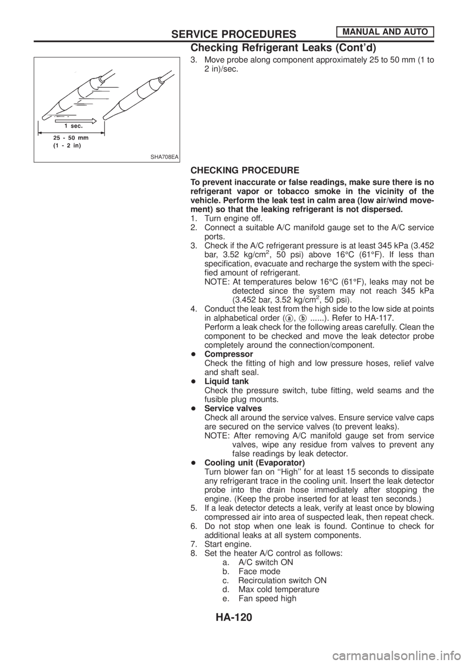
3. Move probe along component approximately 25 to 50 mm (1 to
2 in)/sec.
CHECKING PROCEDURE
To prevent inaccurate or false readings, make sure there is no
refrigerant vapor or tobacco smoke in the vicinity of the
vehicle. Perform the leak test in calm area (low air/wind move-
ment) so that the leaking refrigerant is not dispersed.
1. Turn engine off.
2. Connect a suitable A/C manifold gauge set to the A/C service
ports.
3. Check if the A/C refrigerant pressure is at least 345 kPa (3.452
bar, 3.52 kg/cm
2, 50 psi) above 16ÉC (61ÉF). If less than
speci®cation, evacuate and recharge the system with the speci-
®ed amount of refrigerant.
NOTE: At temperatures below 16ÉC (61ÉF), leaks may not be
detected since the system may not reach 345 kPa
(3.452 bar, 3.52 kg/cm
2, 50 psi).
4. Conduct the leak test from the high side to the low side at points
in alphabetical order (j
a,jb......). Refer to HA-117.
Perform a leak check for the following areas carefully. Clean the
component to be checked and move the leak detector probe
completely around the connection/component.
+Compressor
Check the ®tting of high and low pressure hoses, relief valve
and shaft seal.
+Liquid tank
Check the pressure switch, tube ®tting, weld seams and the
fusible plug mounts.
+Service valves
Check all around the service valves. Ensure service valve caps
are secured on the service valves (to prevent leaks).
NOTE: After removing A/C manifold gauge set from service
valves, wipe any residue from valves to prevent any
false readings by leak detector.
+Cooling unit (Evaporator)
Turn blower fan on ``High'' for at least 15 seconds to dissipate
any refrigerant trace in the cooling unit. Insert the leak detector
probe into the drain hose immediately after stopping the
engine. (Keep the probe inserted for at least ten seconds.)
5. If a leak detector detects a leak, verify at least once by blowing
compressed air into area of suspected leak, then repeat check.
6. Do not stop when one leak is found. Continue to check for
additional leaks at all system components.
7. Start engine.
8. Set the heater A/C control as follows:
a. A/C switch ON
b. Face mode
c. Recirculation switch ON
d. Max cold temperature
e. Fan speed high
SHA708EA
SERVICE PROCEDURESMANUAL AND AUTO
Checking Refrigerant Leaks (Cont'd)
HA-120