Page 1144 of 1226

Trouble Diagnoses Introduction
CAUTION:
+Do not use a circuit tester to check SRS harness connectors unless instructed to in this Service
Manual. SRS wiring harnesses except for ``SEAT BELT PRE-TENSIONER'' can be identi®ed with
yellow harness protector or yellow insulation tape before the harness connectors.
+Do not attempt to repair, splice or modify the SRS wiring harness. If the harness is damaged,
replace it with a new one.
+Keep ground portion clean.
DIAGNOSIS FUNCTION
The SRS self-diagnosis results can be read by using ``AIR BAG'' warning lamp and/or CONSULT.
System Using CONSULT Using warning lamp
Seat belt pre-tensioner X Ð
Air bag Driver air bag X X
Front passenger air bag X X
The reading of these results is accomplished using one of two modes Ð ``User mode'' and ``Diagnosis mode''.
The User mode is exclusively prepared for the customer (driver). This mode warns the driver of a system
malfunction through the operation of the ``AIR BAG'' warning lamp.
The Diagnosis mode allows the technician to locate and inspect the malfunctioning part.
The mode applications for the ``AIR BAG'' warning lamp and CONSULT are as follows:
User mode Diagnosis mode Display type
``AIR BAG'' warning lamp X X ON-OFF operation
CONSULT Ð X Monitoring
DIAGNOSIS MODE FOR CONSULT
+``SELF-DIAG [CURRENT]''
A current Self-diagnosis result (also indicated by the warning lamp ¯ashes in the Diagnosis mode) is dis-
played on the CONSULT screen in real time. This refers to a malfunctioning part requiring repairs.
+``SELF-DIAG [PAST]''
Diagnosis results previously stored in the memory are displayed on the CONSULT screen. The stored
results are not erased until memory erasing is executed.
+``TROUBLE DIAG RECORD''
With ``TROUBLE DIAG RECORD'', diagnosis results previously erased by a reset operation can be dis-
played on the CONSULT screen.
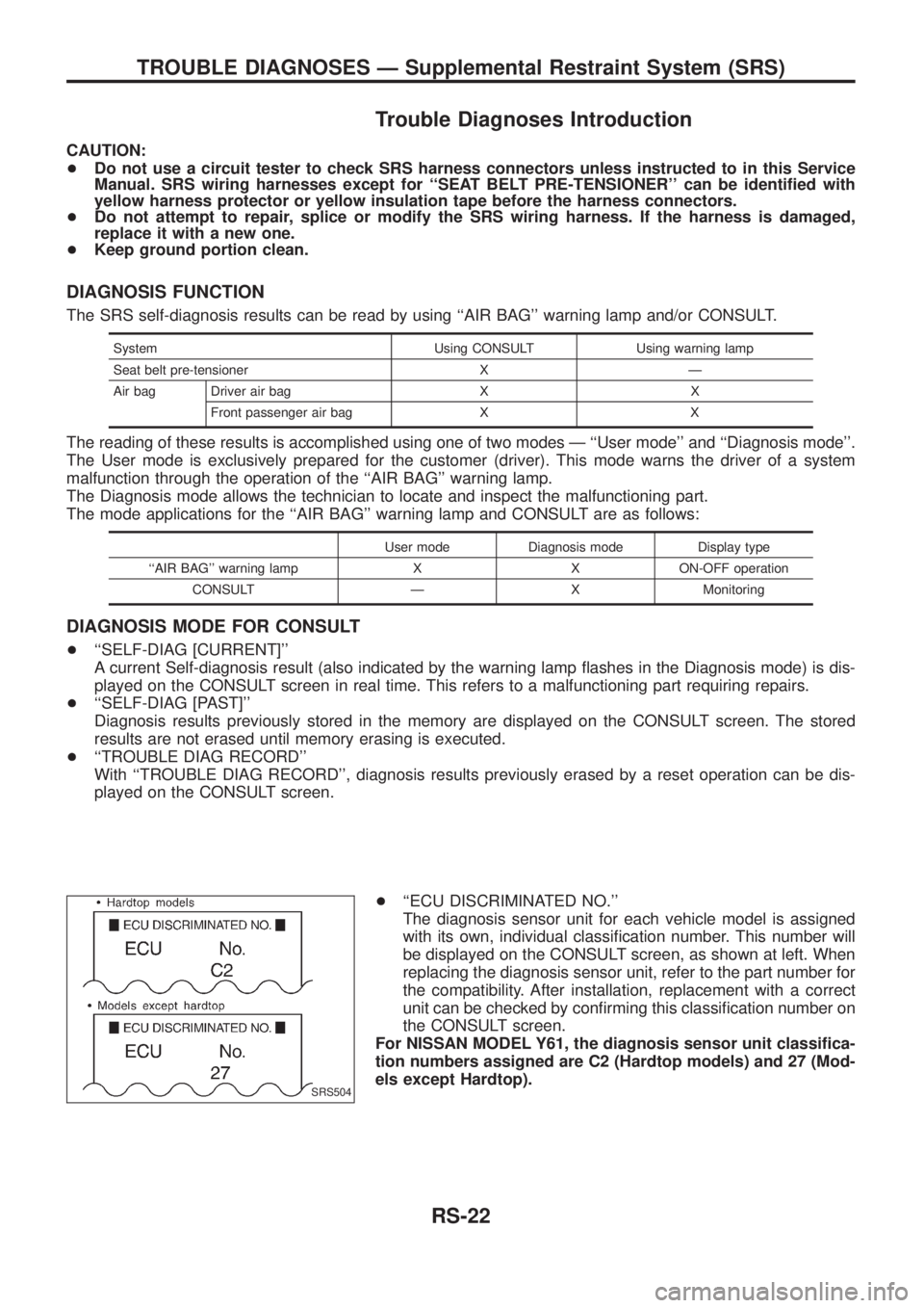
+``ECU DISCRIMINATED NO.''
The diagnosis sensor unit for each vehicle model is assigned
with its own, individual classi®cation number. This number will
be displayed on the CONSULT screen, as shown at left. When
replacing the diagnosis sensor unit, refer to the part number for
the compatibility. After installation, replacement with a correct
unit can be checked by con®rming this classi®cation number on
the CONSULT screen.
For NISSAN MODEL Y61, the diagnosis sensor unit classi®ca-
tion numbers assigned are C2 (Hardtop models) and 27 (Mod-
els except Hardtop).
SRS504
TROUBLE DIAGNOSES Ð Supplemental Restraint System (SRS)
RS-22
Page 1168 of 1226
Part SRS (except the
side air bag) is acti-
vatedSRS is NOT activated
Instrument panel 1. When passenger air bag in¯ates, check the following points for bending, deformities or cracks.
+Opening portion for passenger air bag
SRS472
+Passenger air bag module brackets
SRS473
+The portions securing the instrument panel
SRS474
2. If no damage is found, reinstall the instrument panel.
3. If damagedÐREPLACE the instrument panel with bolts.
COLLISION DIAGNOSIS
RS-46
Page 1178 of 1226

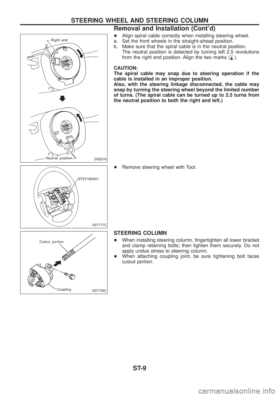
+Align spiral cable correctly when installing steering wheel.
a. Set the front wheels in the straight-ahead position.
b. Make sure that the spiral cable is in the neutral position.
The neutral position is detected by turning left 2.5 revolutions
from the right end position. Align the two marks (
,
m).
CAUTION:
The spiral cable may snap due to steering operation if the
cable is installed in an improper position.
Also, with the steering linkage disconnected, the cable may
snap by turning the steering wheel beyond the limited number
of turns. (The spiral cable can be turned up to 2.5 turns from
the neutral position to both the right and left.)
+Remove steering wheel with Tool.
STEERING COLUMN
+When installing steering column, ®ngertighten all lower bracket
and clamp retaining bolts; then tighten them securely. Do not
apply undue stress to steering column.
+When attaching coupling joint, be sure tightening bolt faces
cutout portion.
SRS276
SST777C
SST759C
STEERING WHEEL AND STEERING COLUMN
Removal and Installation (Cont'd)
ST-9
Page 1182 of 1226
Removal and Installation
Before removal, clean gear housing and oil pump exteriors
using a steam cleaner. Then dry with compressed air.
+Plug openings of gear housing, and securely locate hose con-
nectors at a position higher than oil pump and cover with paper
towels.
+Be extremely careful to prevent entry of foreign matter into
hoses through connectors.
+When installing pitman arm, align four grooves of pitman arm
serrations with four projections of sector shaft serrations, and
install and tighten lock washer and nut.
Inspection
Do not disassemble for power steering gear assembly.
TURNING TORQUE MEASUREMENT
1. Measure turning torque at 360É position.
a. Install steering gear on Tool.
SST774C
SST040-A
POWER STEERING GEAR (Model: PB69K)
ST-13
Page 1208 of 1226
9. Pull out clutch gear and mainshaft rear bearing.
10. Remove 2-4 coupling sleeve with 2-4 shift fork.
11. Remove front drive shaft assembly, drive chain and front drive
sprocket by tapping front end of front drive shaft.
12. Remove bolts securing bearing retainer and then remove bear-
ing retainer.
SMT111B
SMT112B
SMT113B
SMT115B
DISASSEMBLY
TF-15
Page 1209 of 1226
13. Remove bolts securing center case to front case and then
separate center case and front case.
14. Measure end play of low gear.
Standard:
0.20 - 0.35 mm (0.0079 - 0.0138 in)
Refer to SDS, TF-33.
+If end play is beyond the maximum value, check low gear and
L & H hub for wear.
15. Disassemble center case assembly.
a. Remove snap ring from mainshaft.
b. Pull out low gear with L & H hub.
c. Remove mainshaft by tapping front end of mainshaft.
SMT116B
SMT117B
SMT118B
SMT119B
SMT120B
DISASSEMBLY
TF-16
Page 1210 of 1226
16. Disassemble front case assembly.
a. Remove the following parts.
+4WD switch
+Neutral position switch
+Check plugs
+Check springs
+Check balls
+Be careful not to lose the check balls.
b. Remove 2-4 shift rod.
c. Remove L & H shift rod and fork assembly with coupling sleeve.
d. Remove needle bearing from main gear.
e. Remove bolts securing front case cover and then remove it.
SMT259D
SMT122B
SMT260D
SMT124B
SMT125B
DISASSEMBLY
TF-17