Page 96 of 1226
Door Trim
REMOVAL Ð Door trim
V1Remove inside handle escutcheon.
V2Remove door armrest.
V3Remove screw securing power window switches, then disconnect the connector.
V4Remove screw securing door trim.
V5Remove clips securing door trim.
V6Lift out door trim.
SBT530
INTERIOR TRIM
BT-18
Page 98 of 1226
Roof Trim
REMOVAL Ð Headlining (WAGON)
V1Remove front, rear and 3rd seats. Refer to ``SEAT'' for details, BT-32.
V2Remove front, rear and 3rd seat belts. Refer to ``SEAT BELTS'' in RS section for details.
V3Remove body side trim. Refer to ``Side and Floor Trim'' for details, BT-14.
V4Remove roof console assembly, then disconnect connectors.
V5Remove inside mirror assembly.
V6Remove sun visors.
V7Remove interior lamp assembly.
V8Remove luggage room lamp assembly.
V9Remove assist grips.
V10Remove clips securing headlining.
V11Remove rear headlining from vehicle through either back door.
V12Remove front headlining from vehicle through either back door.
SBT531
INTERIOR TRIM
BT-20
Page 100 of 1226
REMOVAL Ð Headlining (HARDTOP)
V1Remove front and rear seats. Refer to ``SEAT'' for details, BT-32.
V2Remove front and rear seat belts. Refer to ``SEAT BELTS'' in RS section for details.
V3Remove body side trim. Refer to ``Side and Floor Trim'' for details, BT-14.
V4Remove roof console assembly, then disconnect connector.
V5Remove inside mirror assembly.
V6Remove sun visors.
V7Remove interior lamp assembly.
V8Remove assist grips.
V9Remove clips securing headlining from vehicle through either back door.
SBT532
INTERIOR TRIM
Roof Trim (Cont'd)
BT-22
Page 102 of 1226
Back Door Trim
REMOVAL Ð Back door trim
V1Remove bolts securing pull handle (LH only).
V2Remove inside handle escutcheon (LH only).
V3Remove clip securing high-mounted stop lamp cover (RH only).
V4Remove back door cover (RH only).
V5Remove clips securing back door upper garnish.
V6Remove clips securing back door trim.
V7Pull out back door trim.
SBT533
INTERIOR TRIM
BT-24
Page 120 of 1226

REMOVAL
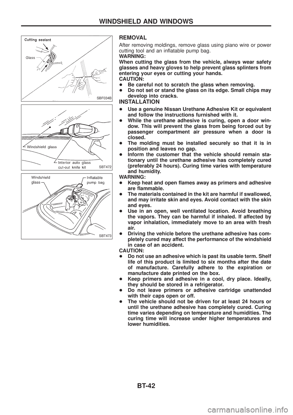
After removing moldings, remove glass using piano wire or power
cutting tool and an in¯atable pump bag.
WARNING:
When cutting the glass from the vehicle, always wear safety
glasses and heavy gloves to help prevent glass splinters from
entering your eyes or cutting your hands.
CAUTION:
+Be careful not to scratch the glass when removing.
+Do not set or stand the glass on its edge. Small chips may
develop into cracks.
INSTALLATION
+Use a genuine Nissan Urethane Adhesive Kit or equivalent
and follow the instructions furnished with it.
+While the urethane adhesive is curing, open a door win-
dow. This will prevent the glass from being forced out by
passenger compartment air pressure when a door is
closed.
+The molding must be installed securely so that it is in
position and leaves no gap.
+Inform the customer that the vehicle should remain sta-
tionary until the urethane adhesive has completely cured
(preferably 24 hours). Curing time varies with temperature
and humidity.
WARNING:
+Keep heat and open ¯ames away as primers and adhesive
are ¯ammable.
+The materials contained in the kit are harmful if swallowed,
and may irritate skin and eyes. Avoid contact with the skin
and eyes.
+Use in an open, well ventilated location. Avoid breathing
the vapors. They can be harmful if inhaled. If affected by
vapor inhalation, immediately move to an area with fresh
air.
+Driving the vehicle before the urethane adhesive has com-
pletely cured may affect the performance of the windshield
in case of an accident.
CAUTION:
+Do not use an adhesive which is past its usable term. Shelf
life of this product is limited to six months after the date
of manufacture. Carefully adhere to the expiration or
manufacture date printed on the box.
+Keep primers and adhesive in a cool, dry place. Ideally,
they should be stored in a refrigerator.
+Do not leave primers or adhesive cartridge unattended
with their caps open or off.
+The vehicle should not be driven for at least 24 hours or
until the urethane adhesive has completely cured. Curing
time varies depending on temperature and humidities. The
curing time will increase under higher temperatures and
lower humidities.
SBF034B
SBT472
SBT473
WINDSHIELD AND WINDOWS
BT-42
Page 124 of 1226
Door Mirror
CAUTION:
Be careful not to scratch door rearview mirror body.
.For Wiring Diagram, refer to ``POWER DOOR MIRROR'' in EL section.
REMOVAL Ð Door mirror
V1Remove door trim. Refer to ``Door Trim'' for details, BT-18.
V2Remove clip securing inner cover, then remove inner cover.
V3Roll back sealing screen and remove door mirror harness connector.
V4Remove door mirror harness clip.
V5Remove bolts securing door mirror, then remove door mirror assembly.
SBT559
MIRROR
BT-46
Page 157 of 1226

Precautions
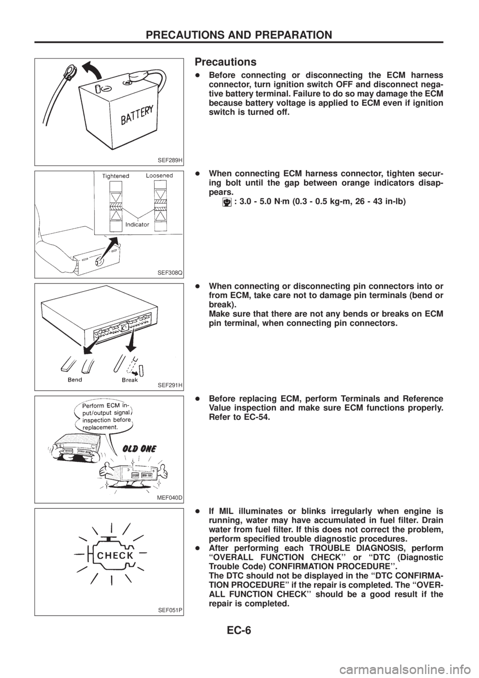
+Before connecting or disconnecting the ECM harness
connector, turn ignition switch OFF and disconnect nega-
tive battery terminal. Failure to do so may damage the ECM
because battery voltage is applied to ECM even if ignition
switch is turned off.
+When connecting ECM harness connector, tighten secur-
ing bolt until the gap between orange indicators disap-
pears.
: 3.0 - 5.0 Nzm (0.3 - 0.5 kg-m, 26 - 43 in-lb)
+When connecting or disconnecting pin connectors into or
from ECM, take care not to damage pin terminals (bend or
break).
Make sure that there are not any bends or breaks on ECM
pin terminal, when connecting pin connectors.
+Before replacing ECM, perform Terminals and Reference
Value inspection and make sure ECM functions properly.
Refer to EC-54.
+If MIL illuminates or blinks irregularly when engine is
running, water may have accumulated in fuel ®lter. Drain
water from fuel ®lter. If this does not correct the problem,
perform speci®ed trouble diagnostic procedures.
+After performing each TROUBLE DIAGNOSIS, perform
``OVERALL FUNCTION CHECK'' or ``DTC (Diagnostic
Trouble Code) CONFIRMATION PROCEDURE''.
The DTC should not be displayed in the ``DTC CONFIRMA-
TION PROCEDUREº if the repair is completed. The ``OVER-
ALL FUNCTION CHECK'' should be a good result if the
repair is completed.
SEF289H
SEF308Q
SEF291H
MEF040D
SEF051P
PRECAUTIONS AND PREPARATION
EC-6
Page 181 of 1226

DTC and MIL Detection Logic
When a malfunction is detected for the ®rst time, the malfunction (DTC) is stored in the ECM memory.
The MIL will light up each time the ECM detects malfunction. However, if the same malfunction is experienced
in two consecutive driving patterns and the engine is still running, the MIL will stay lit up. For diagnostic items
causing the MIL to light up, refer to ``DIAGNOSTIC TROUBLE CODE INDEX'', EC-1.
Diagnostic Trouble Code (DTC)
HOW TO READ DTC
The diagnostic trouble code can be read by the following methods.
1. The number of blinks of the malfunction indicator lamp in the Diagnostic Test Mode II (Self-Diagnostic
Results) Examples: 11, 13, 14, etc.
These DTCs are controlled by NISSAN.
2. CONSULT Examples: ``CAM POS SEN (PUMP)'', etc.
+Output of the trouble code means that the indicated circuit has a malfunction. However, in the Mode
II it does not indicate whether the malfunction is still occurring or occurred in the past and returned
to normal.
CONSULT can identify them. Therefore, using CONSULT (if available) is recommended.
HOW TO ERASE DTC
The diagnostic trouble code can be erased by the following methods.
Selecting ``ERASE'' in the ``SELF-DIAG RESULTS'' mode with CONSULT.
Changing the diagnostic test mode from Diagnostic Test Mode II to Mode I. (Refer to EC-32.)
+If the battery terminal is disconnected, the diagnostic trouble code will be lost within 24 hours.
+When you erase the DTC, using CONSULT is easier and quicker than switching the diagnostic test
modes.
HOW TO ERASE DTC (With CONSULT)
1. If the ignition switch stays ``ON'' after repair work, be sure to turn ignition switch ``OFF'' once. Wait at least
5 seconds and then turn it ``ON'' (Engine stopped) again.
2. Turn CONSULT ``ON'' and touch ``ENGINE''.
3. Touch ``SELF-DIAG RESULTS''.
4. Touch ``ERASE''. (The DTC in the ECM will be erased.)
HOW TO ERASE DTC (No Tools)
1. If the ignition switch stays ``ON'' after repair work, be sure to turn ignition switch ``OFF'' once. Wait at least
5 seconds and then turn it ``ON'' again.
2. Change the diagnostic test mode from Mode II to Mode I. (Refer to EC-32.)
SEF691S
ON BOARD DIAGNOSTIC SYSTEM DESCRIPTION
EC-30