Page 186 of 1226

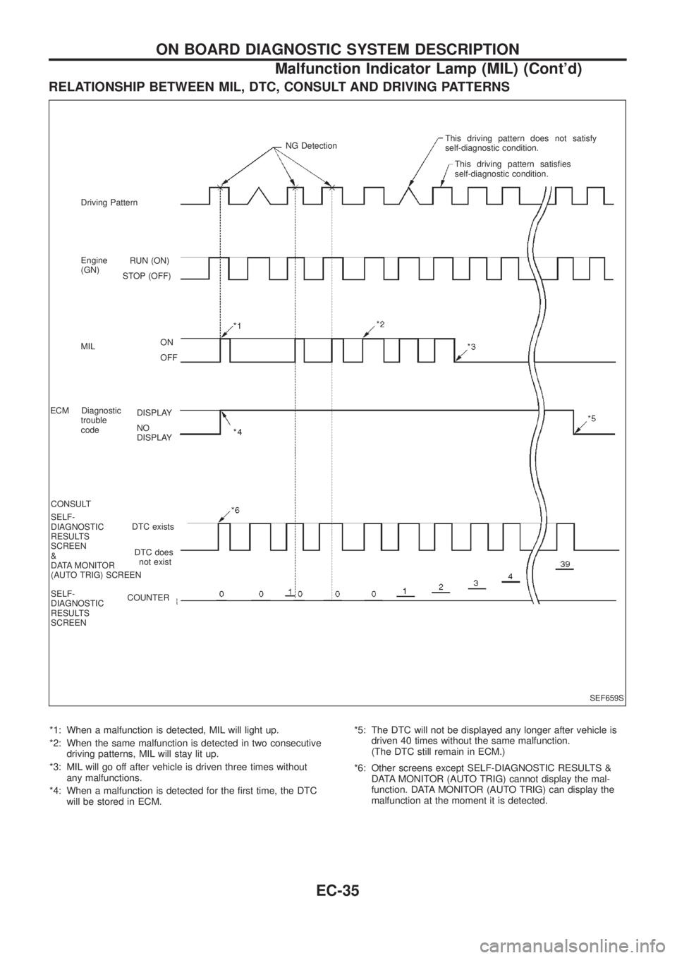
RELATIONSHIP BETWEEN MIL, DTC, CONSULT AND DRIVING PATTERNS
*1: When a malfunction is detected, MIL will light up.
*2: When the same malfunction is detected in two consecutive
driving patterns, MIL will stay lit up.
*3: MIL will go off after vehicle is driven three times without
any malfunctions.
*4: When a malfunction is detected for the ®rst time, the DTC
will be stored in ECM.*5: The DTC will not be displayed any longer after vehicle is
driven 40 times without the same malfunction.
(The DTC still remain in ECM.)
*6: Other screens except SELF-DIAGNOSTIC RESULTS &
DATA MONITOR (AUTO TRIG) cannot display the mal-
function. DATA MONITOR (AUTO TRIG) can display the
malfunction at the moment it is detected.
SEF659S
RUN (ON)
STOP (OFF)
ON
OFF
DISPLAY
NO
DISPLAY
DTC exists
DTC does
not exist
COUNTER Driving Pattern
Engine
(GN)
MIL
ECM Diagnostic
trouble
code
CONSULT
SELF-
DIAGNOSTIC
RESULTS
SCREEN
&
DATA MONITOR
(AUTO TRIG) SCREEN
SELF-
DIAGNOSTIC
RESULTS
SCREENNG DetectionThis driving pattern does not satisfy
self-diagnostic condition.
This driving pattern satis®es
self-diagnostic condition.
ON BOARD DIAGNOSTIC SYSTEM DESCRIPTION
Malfunction Indicator Lamp (MIL) (Cont'd)
EC-35
Page 198 of 1226

jA
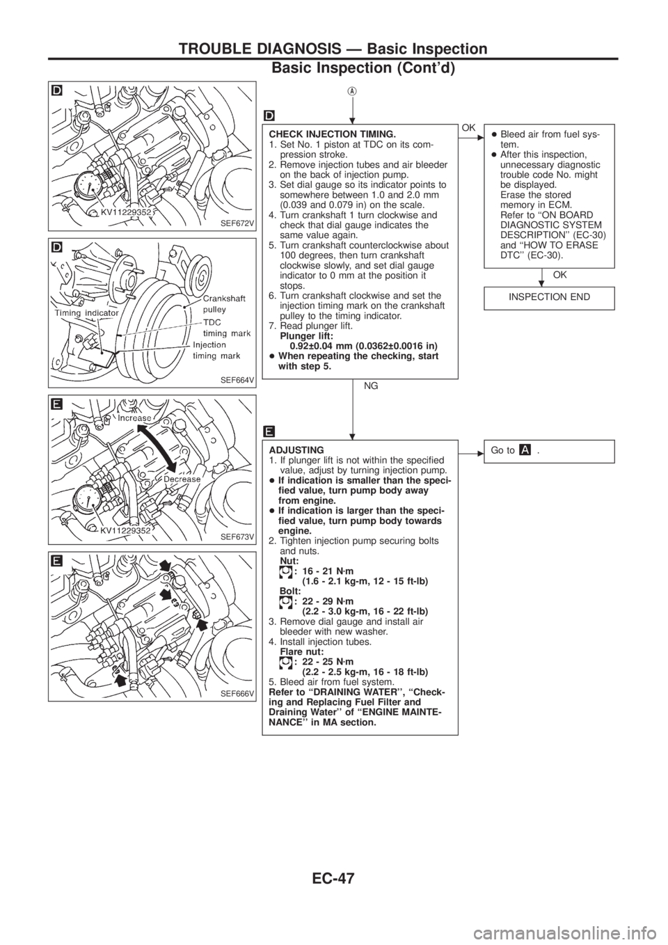
CHECK INJECTION TIMING.
1. Set No. 1 piston at TDC on its com-
pression stroke.
2. Remove injection tubes and air bleeder
on the back of injection pump.
3. Set dial gauge so its indicator points to
somewhere between 1.0 and 2.0 mm
(0.039 and 0.079 in) on the scale.
4. Turn crankshaft 1 turn clockwise and
check that dial gauge indicates the
same value again.
5. Turn crankshaft counterclockwise about
100 degrees, then turn crankshaft
clockwise slowly, and set dial gauge
indicator to 0 mm at the position it
stops.
6. Turn crankshaft clockwise and set the
injection timing mark on the crankshaft
pulley to the timing indicator.
7. Read plunger lift.
Plunger lift:
0.92 0.04 mm (0.0362 0.0016 in)
+When repeating the checking, start
with step 5.
NG
cOK
+Bleed air from fuel sys-
tem.
+After this inspection,
unnecessary diagnostic
trouble code No. might
be displayed.
Erase the stored
memory in ECM.
Refer to ``ON BOARD
DIAGNOSTIC SYSTEM
DESCRIPTION'' (EC-30)
and ``HOW TO ERASE
DTC'' (EC-30).
OK
INSPECTION END
ADJUSTING
1. If plunger lift is not within the speci®ed
value, adjust by turning injection pump.
+If indication is smaller than the speci-
®ed value, turn pump body away
from engine.
+If indication is larger than the speci-
®ed value, turn pump body towards
engine.
2. Tighten injection pump securing bolts
and nuts.
Nut:
: 16-21Nzm
(1.6 - 2.1 kg-m, 12 - 15 ft-lb)
Bolt:
: 22-29Nzm
(2.2 - 3.0 kg-m, 16 - 22 ft-lb)
3. Remove dial gauge and install air
bleeder with new washer.
4. Install injection tubes.
Flare nut:
: 22-25Nzm
(2.2 - 2.5 kg-m, 16 - 18 ft-lb)
5. Bleed air from fuel system.
Refer to ``DRAINING WATER'', ``Check-
ing and Replacing Fuel Filter and
Draining Water'' of ``ENGINE MAINTE-
NANCE'' in MA section.
cGo to.
SEF672V
SEF664V
SEF673V
SEF666V
.
.
.
TROUBLE DIAGNOSIS Ð Basic Inspection
Basic Inspection (Cont'd)
EC-47
Page 205 of 1226
ECM Terminals and Reference Value
PREPARATION
1. ECM is located behind the instrument lower panel. For this
inspection, remove the driver's side instrument lower cover.
2. Remove ECM harness protector.
3. Perform all voltage measurements with the connector con-
nected. Extend tester probe as shown to perform tests easily.
+Open harness securing clip to make testing easier.
+Use extreme care not to touch 2 pins at one time.
+Data is for comparison and may not be exact.
Be sure ECM unit is properly grounded before checking.
SEF519V
AEC913
SEF367I
SEF665S
TROUBLE DIAGNOSIS Ð General Description
EC-54
Page 306 of 1226

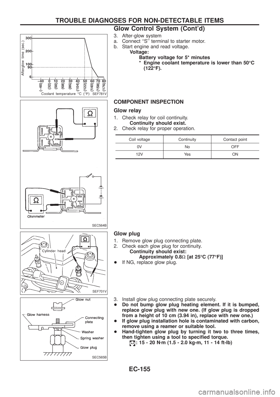
3. After-glow system
a. Connect ``S'' terminal to starter motor.
b. Start engine and read voltage.
Voltage:
Battery voltage for 5* minutes
* Engine coolant temperature is lower than 50ÉC
(122ÉF).
COMPONENT INSPECTION
Glow relay
1. Check relay for coil continuity.
Continuity should exist.
2. Check relay for proper operation.
Coil voltage Continuity Contact point
0V No OFF
12V Yes ON
Glow plug
1. Remove glow plug connecting plate.
2. Check each glow plug for continuity.
Continuity should exist:
Approximately 0.8W[at 25ÉC (77ÉF)]
+If NG, replace glow plug.
3. Install glow plug connecting plate securely.
+Do not bump glow plug heating element. If it is bumped,
replace glow plug with new one. (If glow plug is dropped
from a height of 10 cm (3.94 in), replace with new one.)
+If glow plug installation hole is contaminated with carbon,
remove using a reamer or suitable tool.
+Hand-tighten glow plug by turning it two to three times,
then tighten using a tool to speci®ed torque.
:15-20Nzm (1.5 - 2.0 kg-m, 11 - 14 ft-lb)
SEF781V
SEC564B
SEF701V
SEC565B
TROUBLE DIAGNOSES FOR NON-DETECTABLE ITEMS
Glow Control System (Cont'd)
EC-155
Page 394 of 1226
YOKE CHECK
Magnet is secured to yoke by bonding agent. Check magnet to see
that it is secured to yoke and for any cracks. Replace malfunction-
ing parts as an assembly.
CAUTION:
Do not clamp yoke in a vice or strike it with a hammer.
ARMATURE CHECK
1. Continuity test (between two segments side by side).
+No continuity ... Replace.
2. Insulation test (between each commutator bar and shaft).
+Continuity exists. ... Replace.
3. Check commutator surface.
+Rough ... Sand lightly with No. 500 - 600 emery paper.
4. Check diameter of commutator.
Commutator minimum diameter:
Refer to SDS (EL-51).
+Less than speci®ed value ... Replace.
SEL305H
SEL019Z
SEL020Z
SEL021Z
STARTING SYSTEM
Inspection (Cont'd)
EL-49
Page 403 of 1226
Replacement
For removal and installation of spiral cable, refer to RS section
[``Installation Ð Air Bag Module and Spiral Cable'', ``SUPPLE-
MENTAL RESTRAINT SYSTEM (SRS)''].
+Each switch can be replaced without removing combination
switch base.
+To remove combination switch base, remove base attaching
screw.
+Before installing the steering wheel, align the steering wheel
guide pins with the screws which secure the combination switch
as shown in the left ®gure.
MEL304D
MEL326G
SEL151V
COMBINATION SWITCH
EL-58
Page 454 of 1226
Flexible Print Circuit (FPC)
Tachometer, fuel gauge and water temperature gauge are con-
nected with uni®ed meter control unit (speedometer) by Flexible
Print Circuit (FPC) connector. When replace or remove and install
uni®ed control unit (speedometer), disconnect and connect FPC
connector according to the following steps.
DISCONNECT
1. Open connector cover.
2. Release connector lock by holding both ends of it and pulling it
up.
3. Disconnect FPC by pulling it up.
CONNECT
1. Insert FPC into connector and lock connector pushing FPC
downward.
2. Check secure connection of FPC.
3. Check continuity of check land terminal for secure connection
of FPC.
Resistance: 0W
4. Close connector cover.
SEL109V
SEL114V
METER AND GAUGES
EL-109
Page 455 of 1226

Trouble Diagnoses
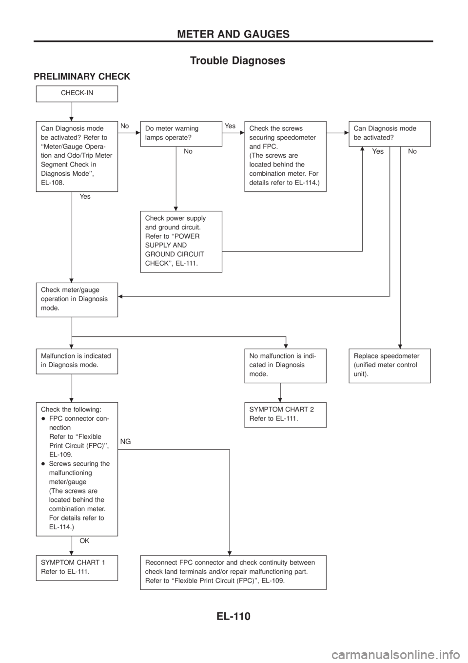
PRELIMINARY CHECK
CHECK-IN
Can Diagnosis mode
be activated? Refer to
``Meter/Gauge Opera-
tion and Odo/Trip Meter
Segment Check in
Diagnosis Mode'',
EL-108.
Ye s
cNo
Do meter warning
lamps operate?
No
cYe s
Check the screws
securing speedometer
and FPC.
(The screws are
located behind the
combination meter. For
details refer to EL-114.)cCan Diagnosis mode
be activated?
Nom
Check power supply
and ground circuit.
Refer to ``POWER
SUPPLY AND
GROUND CIRCUIT
CHECK'', EL-111.
Check meter/gauge
operation in Diagnosis
mode.b
Ye s
.
Malfunction is indicated
in Diagnosis mode.No malfunction is indi-
cated in Diagnosis
mode.Replace speedometer
(uni®ed meter control
unit).
Check the following:
+FPC connector con-
nection
Refer to ``Flexible
Print Circuit (FPC)'',
EL-109.
+Screws securing the
malfunctioning
meter/gauge
(The screws are
located behind the
combination meter.
For details refer to
EL-114.)
OK
.
NG
SYMPTOM CHART 2
Refer to EL-111.
SYMPTOM CHART 1
Refer to EL-111.Reconnect FPC connector and check continuity between
check land terminals and/or repair malfunctioning part.
Refer to ``Flexible Print Circuit (FPC)'', EL-109.
.
.
.
..
..
.
METER AND GAUGES
EL-110