Page 965 of 1226

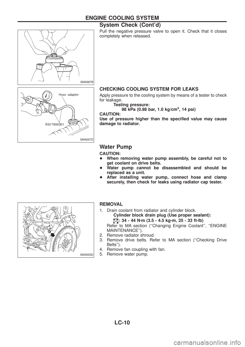
Pull the negative pressure valve to open it. Check that it closes
completely when released.
CHECKING COOLING SYSTEM FOR LEAKS
Apply pressure to the cooling system by means of a tester to check
for leakage.
Testing pressure:
98 kPa (0.98 bar, 1.0 kg/cm
2, 14 psi)
CAUTION:
Use of pressure higher than the speci®ed value may cause
damage to radiator.
Water Pump
CAUTION:
+When removing water pump assembly, be careful not to
get coolant on drive belts.
+Water pump cannot be disassembled and should be
replaced as a unit.
+After installing water pump, connect hose and clamp
securely, then check for leaks using radiator cap tester.
REMOVAL
1. Drain coolant from radiator and cylinder block.
Cylinder block drain plug (Use proper sealant):
:34-44Nzm (3.5 - 4.5 kg-m, 25 - 33 ft-lb)
Refer to MA section (``Changing Engine Coolant'', ``ENGINE
MAINTENANCE'').
2. Remove radiator shroud.
3. Remove drive belts. Refer to MA section (``Checking Drive
Belts'').
4. Remove fan coupling with fan.
5. Remove water pump.
SMA967B
SMA007D
SMA003D
ENGINE COOLING SYSTEM
System Check (Cont'd)
LC-10
Page 974 of 1226
INSPECTION
1. Apply pressure with Tool.
Speci®ed pressure value:
98 kPa (0.98 bar, 1.0 kg/cm
2, 14 psi)
WARNING:
To prevent the risk of the hose coming undone while under
pressure, securely fasten it down with a hose clamp.
Attach a hose to the oil cooler as well.
2. Check for leakage.
SLC933
SLC934
ENGINE COOLING SYSTEM
Radiator (Aluminum type) (Cont'd)
LC-19
Page 980 of 1226

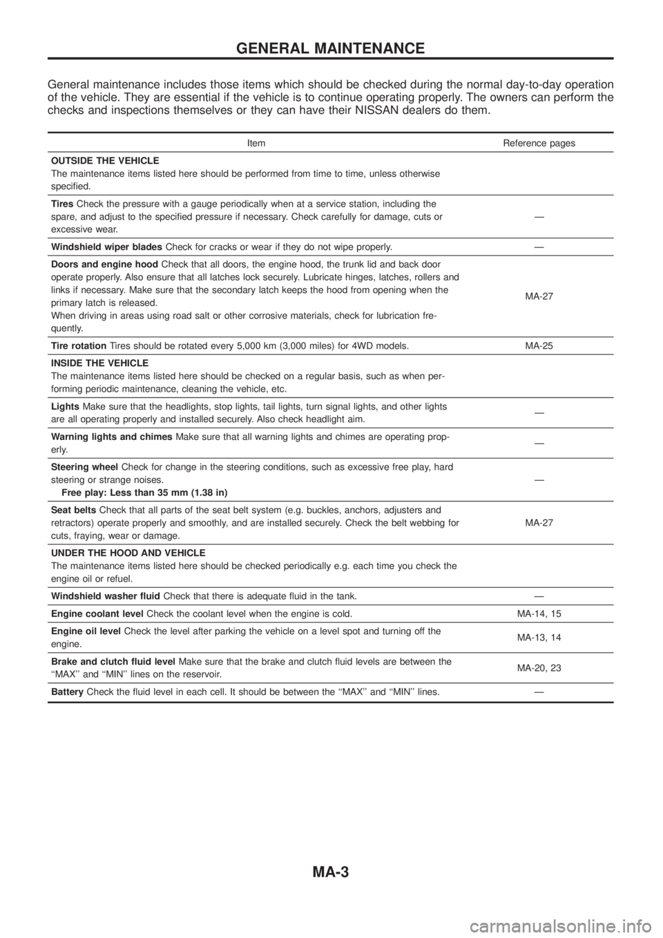
General maintenance includes those items which should be checked during the normal day-to-day operation
of the vehicle. They are essential if the vehicle is to continue operating properly. The owners can perform the
checks and inspections themselves or they can have their NISSAN dealers do them.
Item Reference pages
OUTSIDE THE VEHICLE
The maintenance items listed here should be performed from time to time, unless otherwise
speci®ed.
TiresCheck the pressure with a gauge periodically when at a service station, including the
spare, and adjust to the speci®ed pressure if necessary. Check carefully for damage, cuts or
excessive wear.Ð
Windshield wiper bladesCheck for cracks or wear if they do not wipe properly. Ð
Doors and engine hoodCheck that all doors, the engine hood, the trunk lid and back door
operate properly. Also ensure that all latches lock securely. Lubricate hinges, latches, rollers and
links if necessary. Make sure that the secondary latch keeps the hood from opening when the
primary latch is released.
When driving in areas using road salt or other corrosive materials, check for lubrication fre-
quently.MA-27
Tire rotationTires should be rotated every 5,000 km (3,000 miles) for 4WD models. MA-25
INSIDE THE VEHICLE
The maintenance items listed here should be checked on a regular basis, such as when per-
forming periodic maintenance, cleaning the vehicle, etc.
LightsMake sure that the headlights, stop lights, tail lights, turn signal lights, and other lights
are all operating properly and installed securely. Also check headlight aim.Ð
Warning lights and chimesMake sure that all warning lights and chimes are operating prop-
erly.Ð
Steering wheelCheck for change in the steering conditions, such as excessive free play, hard
steering or strange noises.
Free play: Less than 35 mm (1.38 in)Ð
Seat beltsCheck that all parts of the seat belt system (e.g. buckles, anchors, adjusters and
retractors) operate properly and smoothly, and are installed securely. Check the belt webbing for
cuts, fraying, wear or damage.MA-27
UNDER THE HOOD AND VEHICLE
The maintenance items listed here should be checked periodically e.g. each time you check the
engine oil or refuel.
Windshield washer ¯uidCheck that there is adequate ¯uid in the tank. Ð
Engine coolant levelCheck the coolant level when the engine is cold. MA-14, 15
Engine oil levelCheck the level after parking the vehicle on a level spot and turning off the
engine.MA-13, 14
Brake and clutch ¯uid levelMake sure that the brake and clutch ¯uid levels are between the
``MAX'' and ``MIN'' lines on the reservoir.MA-20, 23
BatteryCheck the ¯uid level in each cell. It should be between the ``MAX'' and ``MIN'' lines. Ð
GENERAL MAINTENANCE
MA-3
Page 996 of 1226
6. Install all injection nozzles with Tool and securely connect fuel
spill tube and delivery tubes.
7. Bleed air from fuel system and check for fuel leakage with
engine running.
Injection nozzle to cylinder head:
:59-69Nzm (6.0 - 7.0 kg-m, 43 - 51 ft-lb)
Spill tube nut:
:39-49Nzm (4.0 - 5.0 kg-m, 29 - 36 ft-lb)
Injection tube:
:20-25Nzm (2.2 - 2.5 kg-m, 16 - 18 ft-lb)
Checking Idle Speed
Inspection should be carried out with gears in ``Neutral'' and
with air conditioner and other electrical loads off.
1. Warm up engine until engine coolant temperature indicator
points to the middle of gauge.
2. Attach a diesel tachotester's pick-up to No. 1 fuel injection tube.
3. Race engine two or three times and check idle speed.
Idle speed:
Unit: rpm
MT 750+50
þ0
Timing Belt Replacement
Refer to EM section.
ENGINE MAINTENANCE
Checking Injection Nozzle (Cont'd)
MA-19
Page 1013 of 1226
Installation
+Apply sealant as below:
+Tighten bolts securing transmission.
Bolt No. Tightening torque Nzm (kg-m, ft-lb)!mm (in)
V139 - 49 (4.0 - 5.0, 29 - 36) 79 (3.11)
V239 - 49 (4.0 - 5.0, 29 - 36) 85 (3.35)
V329 - 39 (3.0 - 4.0, 22 - 29) 79 (3.11)
V429 - 39 (3.0 - 4.0, 22 - 29) 57 (2.24)
V529 - 39 (3.0 - 4.0, 22 - 29) 50 (1.97)
Gusset to engine 29 - 39 (3.0 - 4.0, 22 - 29) 35 (1.38)
SMT550D
SMT322D
REMOVAL AND INSTALLATION
MT-6
Page 1103 of 1226
Removal
CAUTION:
+Before removing the rear axle, disconnect the ABS wheel
sensor from the assembly. Then move it away from the
axle. Failure to do so may result in damage to the sensor
wires and the sensor becoming inoperative.
+Wheel bearing does not require maintenance.
+If growling noise is emitted from wheel bearing during
operation, replace wheel bearing assembly.
+If the wheel bearing assembly is removed, it must be renewed.
The old assembly must not be re-used.
1. Disconnect parking brake cable and brake tube.
2. Remove nuts securing wheel bearing cage with baffle plate.
3. Draw out axle shaft with Tool.
When drawing out axle shaft, be careful not to damage oil seal.
4. Remove O-ring.
5. Remove oil seal with a screwdriver.
Do not reuse oil seal once it is removed.
Always install new one.
6. Remove ABS sensor rotor. Ð Models with ABS Ð
SRA757A
SRA845A
SRA846A
SRA799A
REAR AXLE
RA-7
Page 1113 of 1226
Removal and Installation
1. Loosen the lock nut C, and loosen the A nut. Remove the cable
from the clutch cylinder.
CAUTION:
+Do not remove the B nut because this requires the inner
cable extension adjustment.
+Before installing the A and C nuts, use seal tape to wrap
the clutch cylinder thread area and cable thread area.
2. Remove the clamp and other fasteners which secure the cable.
3. Remove the stabilizer actuator connector.
4. Remove the stabilizer actuator.
5. Remove the clutch cylinder.
6. Before removing the stabilizer control unit, remove cluster lid C
and audio equipment. Refer to the BT section ``INSTRUMENT
PANEL''.
SRA835A
SRA836A
SRA837A
STABILIZER RELEASE DEVICE
RA-17
Page 1125 of 1226
Front Seat Belt
REMOVAL (WAGON)
V1Remove front seat. Refer to ``SEAT'' in BT section for details.
V2Remove adjuster cover.
V3Slide ¯oor anchor cover.
V4Remove ¯oor anchor bolt.
V5Remove shoulder anchor bolt.
V6Remove center pillar upper and lower garnish. Refer to ``Side and Floor Trim'' in BT section for details.
V7Remove bolts securing second sash guide, then remove second sash guide.
V8Remove the bolt securing seat belt pre-tensioner retractor, then remove seat belt and seat belt pre-ten-
sioner retractor.
V9Remove bolts securing seat belt adjuster, then remove seat belt adjuster.
SRS446
SEAT BELTS
RS-3