2006 NISSAN PATROL air condition
[x] Cancel search: air conditionPage 209 of 1226
TER-
MINAL
NO.WIRE
COLORITEM CONDITIONDATA
(DC Voltage and Pulse
Signal)
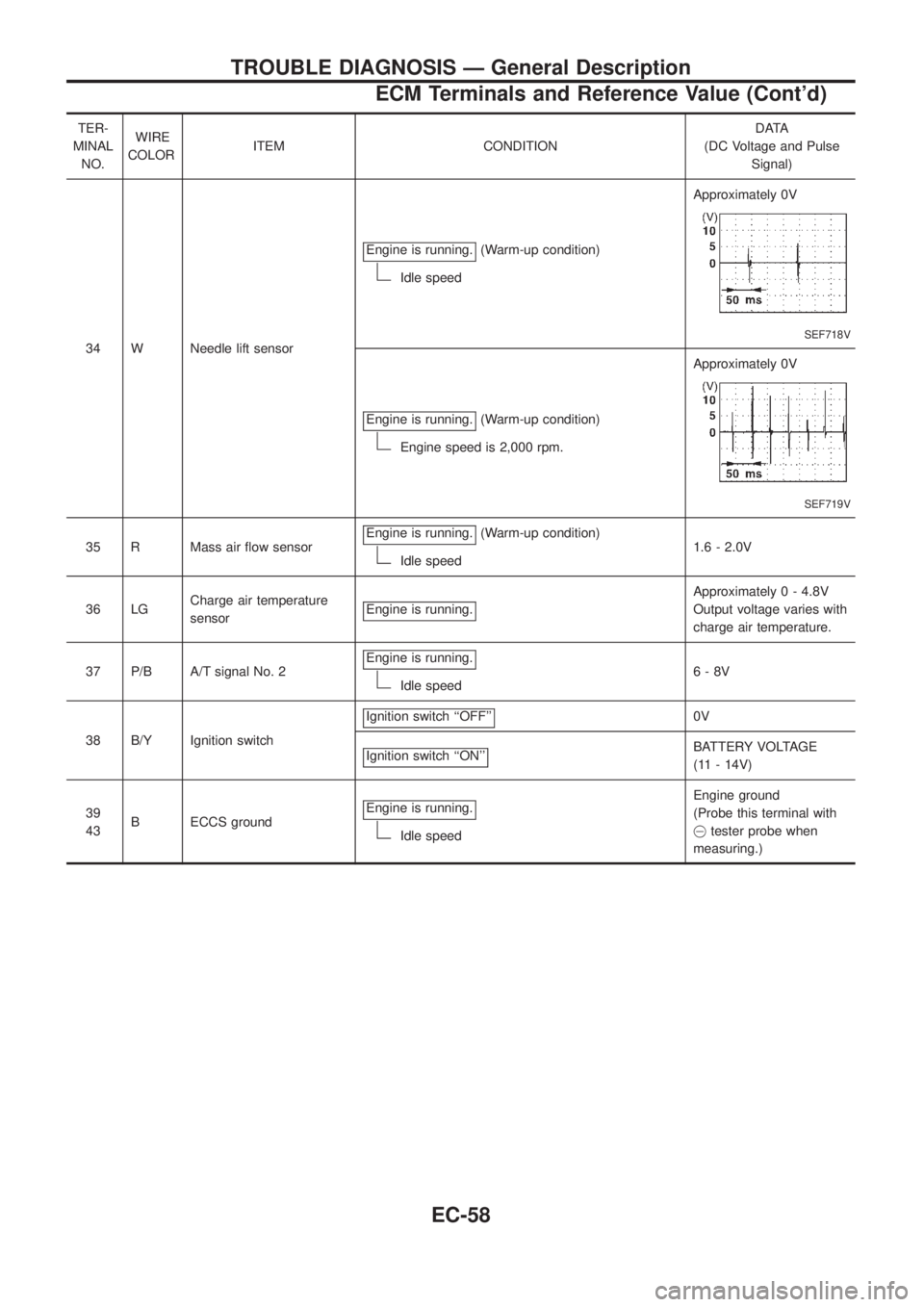
34 W Needle lift sensorEngine is running.
(Warm-up condition)
Idle speedApproximately 0V
SEF718V
Engine is running.(Warm-up condition)
Engine speed is 2,000 rpm.Approximately 0V
SEF719V
35 R Mass air ¯ow sensorEngine is running.(Warm-up condition)
Idle speed1.6 - 2.0V
36 LGCharge air temperature
sensorEngine is running.
Approximately 0 - 4.8V
Output voltage varies with
charge air temperature.
37 P/B A/T signal No. 2Engine is running.
Idle speed6-8V
38 B/Y Ignition switchIgnition switch ``OFF''
0V
Ignition switch ``ON''
BATTERY VOLTAGE
(11 - 14V)
39
43B ECCS groundEngine is running.
Idle speedEngine ground
(Probe this terminal with
@tester probe when
measuring.)
TROUBLE DIAGNOSIS Ð General Description
ECM Terminals and Reference Value (Cont'd)
EC-58
Page 225 of 1226
Mass Air Flow Sensor (MAFS)
COMPONENT DESCRIPTION
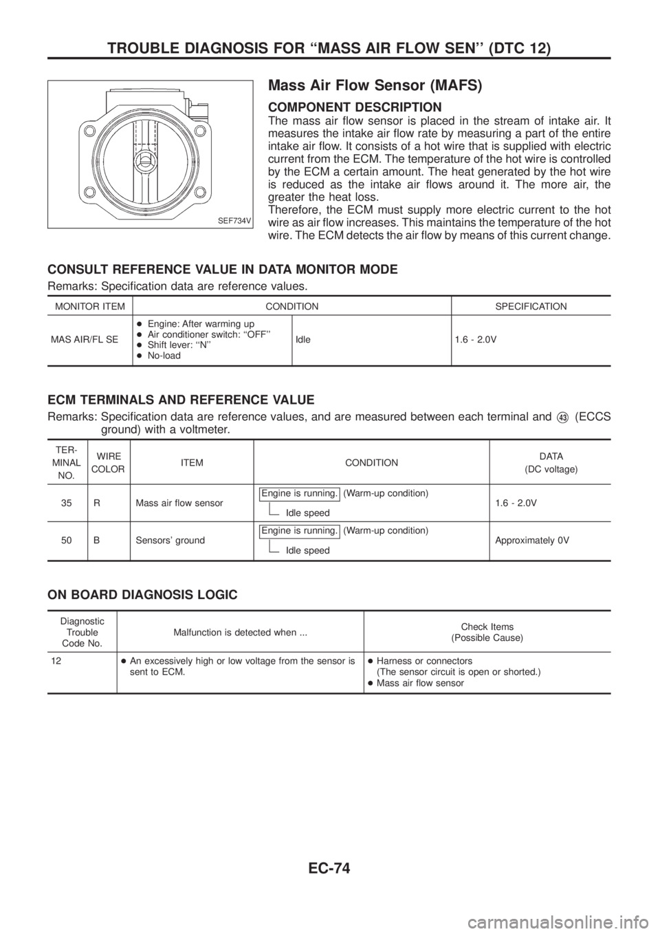
The mass air ¯ow sensor is placed in the stream of intake air. It
measures the intake air ¯ow rate by measuring a part of the entire
intake air ¯ow. It consists of a hot wire that is supplied with electric
current from the ECM. The temperature of the hot wire is controlled
by the ECM a certain amount. The heat generated by the hot wire
is reduced as the intake air ¯ows around it. The more air, the
greater the heat loss.
Therefore, the ECM must supply more electric current to the hot
wire as air ¯ow increases. This maintains the temperature of the hot
wire. The ECM detects the air ¯ow by means of this current change.
CONSULT REFERENCE VALUE IN DATA MONITOR MODE
Remarks: Speci®cation data are reference values.
MONITOR ITEM CONDITION SPECIFICATION
MAS AIR/FL SE+Engine: After warming up
+Air conditioner switch: ``OFF''
+Shift lever: ``N''
+No-loadIdle 1.6 - 2.0V
ECM TERMINALS AND REFERENCE VALUE
Remarks: Speci®cation data are reference values, and are measured between each terminal andV43(ECCS
ground) with a voltmeter.
TER-
MINAL
NO.WIRE
COLORITEM CONDITIONDATA
(DC voltage)
35 R Mass air ¯ow sensorEngine is running.
(Warm-up condition)
Idle speed1.6 - 2.0V
50 B Sensors' groundEngine is running.
(Warm-up condition)
Idle speedApproximately 0V
ON BOARD DIAGNOSIS LOGIC
Diagnostic
Trouble
Code No.Malfunction is detected when ...Check Items
(Possible Cause)
12+An excessively high or low voltage from the sensor is
sent to ECM.+Harness or connectors
(The sensor circuit is open or shorted.)
+Mass air ¯ow sensor
SEF734V
TROUBLE DIAGNOSIS FOR ``MASS AIR FLOW SEN'' (DTC 12)
EC-74
Page 229 of 1226
COMPONENT INSPECTION
Mass air ¯ow sensor
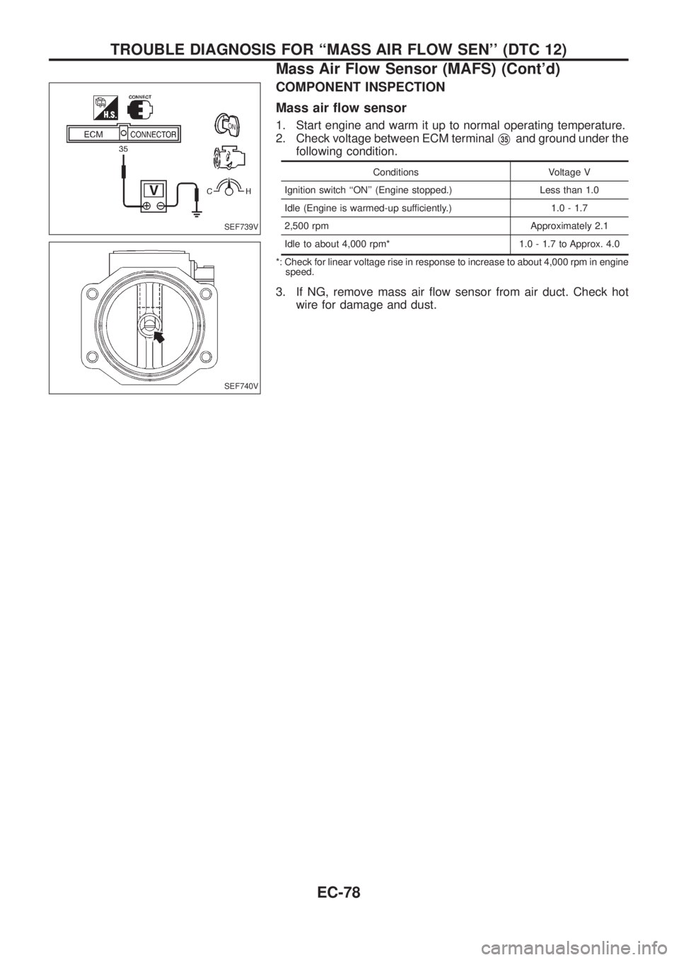
1. Start engine and warm it up to normal operating temperature.
2. Check voltage between ECM terminal
V35and ground under the
following condition.
Conditions Voltage V
Ignition switch ``ON'' (Engine stopped.) Less than 1.0
Idle (Engine is warmed-up sufficiently.) 1.0 - 1.7
2,500 rpm Approximately 2.1
Idle to about 4,000 rpm* 1.0 - 1.7 to Approx. 4.0
*: Check for linear voltage rise in response to increase to about 4,000 rpm in engine
speed.
3. If NG, remove mass air ¯ow sensor from air duct. Check hot
wire for damage and dust.
SEF739V
SEF740V
TROUBLE DIAGNOSIS FOR ``MASS AIR FLOW SEN'' (DTC 12)
Mass Air Flow Sensor (MAFS) (Cont'd)
EC-78
Page 252 of 1226
Injection Timing Control Valve
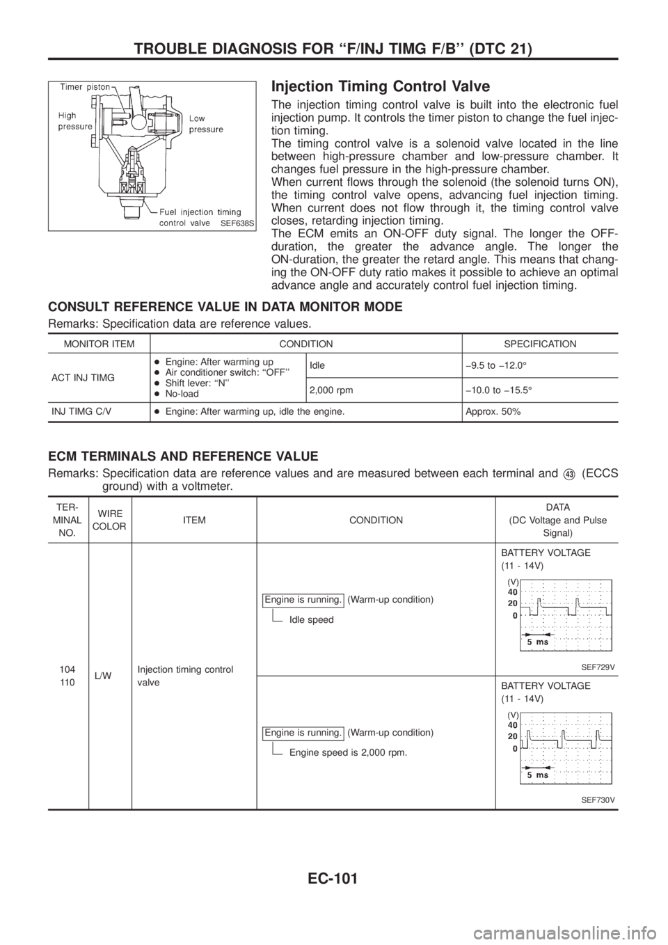
The injection timing control valve is built into the electronic fuel
injection pump. It controls the timer piston to change the fuel injec-
tion timing.
The timing control valve is a solenoid valve located in the line
between high-pressure chamber and low-pressure chamber. It
changes fuel pressure in the high-pressure chamber.
When current ¯ows through the solenoid (the solenoid turns ON),
the timing control valve opens, advancing fuel injection timing.
When current does not ¯ow through it, the timing control valve
closes, retarding injection timing.
The ECM emits an ON-OFF duty signal. The longer the OFF-
duration, the greater the advance angle. The longer the
ON-duration, the greater the retard angle. This means that chang-
ing the ON-OFF duty ratio makes it possible to achieve an optimal
advance angle and accurately control fuel injection timing.
CONSULT REFERENCE VALUE IN DATA MONITOR MODE
Remarks: Speci®cation data are reference values.
MONITOR ITEM CONDITION SPECIFICATION
ACT INJ TIMG+Engine: After warming up
+Air conditioner switch: ``OFF''
+Shift lever: ``N''
+No-loadIdle þ9.5 to þ12.0É
2,000 rpm þ10.0 to þ15.5É
INJ TIMG C/V+Engine: After warming up, idle the engine. Approx. 50%
ECM TERMINALS AND REFERENCE VALUE
Remarks: Speci®cation data are reference values and are measured between each terminal andV43(ECCS
ground) with a voltmeter.
TER-
MINAL
NO.WIRE
COLORITEM CONDITIONDATA
(DC Voltage and Pulse
Signal)
104
11 0L/WInjection timing control
valveEngine is running.
(Warm-up condition)
Idle speedBATTERY VOLTAGE
(11 - 14V)
SEF729V
Engine is running.(Warm-up condition)
Engine speed is 2,000 rpm.BATTERY VOLTAGE
(11 - 14V)
SEF730V
SEF638S
TROUBLE DIAGNOSIS FOR ``F/INJ TIMG F/B'' (DTC 21)
EC-101
Page 264 of 1226
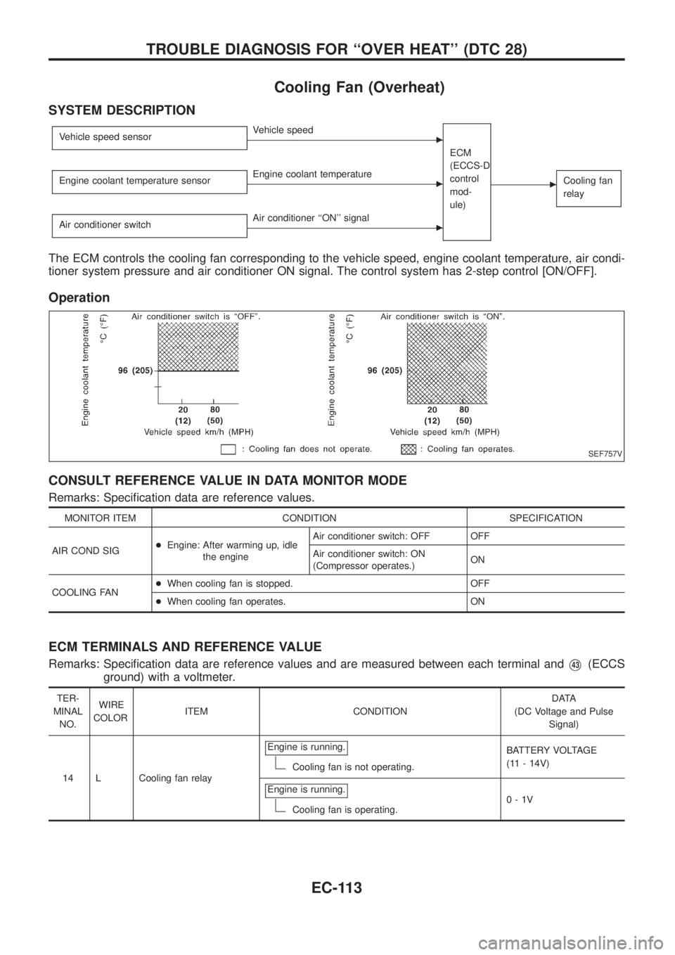
Cooling Fan (Overheat)
SYSTEM DESCRIPTION
Vehicle speed sensorcVehicle speed
ECM
(ECCS-D
control
mod-
ule)
cCooling fan
relayEngine coolant temperature sensorcEngine coolant temperature
Air conditioner switch
cAir conditioner ``ON'' signal
The ECM controls the cooling fan corresponding to the vehicle speed, engine coolant temperature, air condi-
tioner system pressure and air conditioner ON signal. The control system has 2-step control [ON/OFF].
Operation
CONSULT REFERENCE VALUE IN DATA MONITOR MODE
Remarks: Speci®cation data are reference values.
MONITOR ITEM CONDITION SPECIFICATION
AIR COND SIG+Engine: After warming up, idle
the engineAir conditioner switch: OFF OFF
Air conditioner switch: ON
(Compressor operates.)ON
COOLING FAN+When cooling fan is stopped. OFF
+When cooling fan operates. ON
ECM TERMINALS AND REFERENCE VALUE
Remarks: Speci®cation data are reference values and are measured between each terminal andV43(ECCS
ground) with a voltmeter.
TER-
MINAL
NO.WIRE
COLORITEM CONDITIONDATA
(DC Voltage and Pulse
Signal)
14 L Cooling fan relayEngine is running.
Cooling fan is not operating.BATTERY VOLTAGE
(11 - 14V)
Engine is running.
Cooling fan is operating.0-1V
SEF757V
TROUBLE DIAGNOSIS FOR ``OVER HEAT'' (DTC 28)
EC-113
Page 265 of 1226

TER-
MINAL
NO.WIRE
COLORITEM CONDITIONDATA
(DC Voltage and Pulse
Signal)
15 Y/L Air conditioner relayEngine is running.
Air conditioner switch is ``OFF''.BATTERY VOLTAGE
(11 - 14V)
Engine is running.
Both air conditioner switch and blower fan
switch are ``ON''.
(Compressor is operating.)0-1V
ON BOARD DIAGNOSIS LOGIC
This diagnosis continuously monitors the engine coolant temperature.
If the cooling fan or another component in the cooling system malfunctions, engine coolant temperature will
rise.
When the engine coolant temperature reaches an abnormally high temperature condition, a malfunction is
indicated.
Diagnostic Trouble
Code No.Malfunction is detected when ...Check Items
(Possible Cause)
28+Cooling fan does not operate properly (Overheat).
+Cooling fan system does not operate properly (Over-
heat).
+Engine coolant was not added to the system using
the proper ®lling method.+Harness or connectors
(The cooling fan circuit is open or shorted.)
+Cooling fan
+Radiator hose
+Radiator
+Radiator cap
+Water pump
+Thermostat
+Fan belt
+Engine coolant temperature sensor
For more information, refer to ``MAIN 12
CAUSES OF OVERHEATING'', EC-120.
CAUTION:
When a malfunction is indicated, be sure to replace the coolant following the procedure in the MA
section (``Changing Engine Coolant'', ``ENGINE MAINTENANCE''). Also, replace the engine oil.
a. Fill radiator with coolant up to speci®ed level with a ®lling speed of 2 liters per minute. Be sure to
use coolant with the proper mixture ratio. Refer to MA section (``Anti-freeze Coolant Mixture Ratio'',
``RECOMMENDED FLUIDS AND LUBRICANTS'').
b. After re®lling coolant, run engine to ensure that no water-¯ow noise is emitted.
TROUBLE DIAGNOSIS FOR ``OVER HEAT'' (DTC 28)
Cooling Fan (Overheat) (Cont'd)
EC-114
Page 270 of 1226
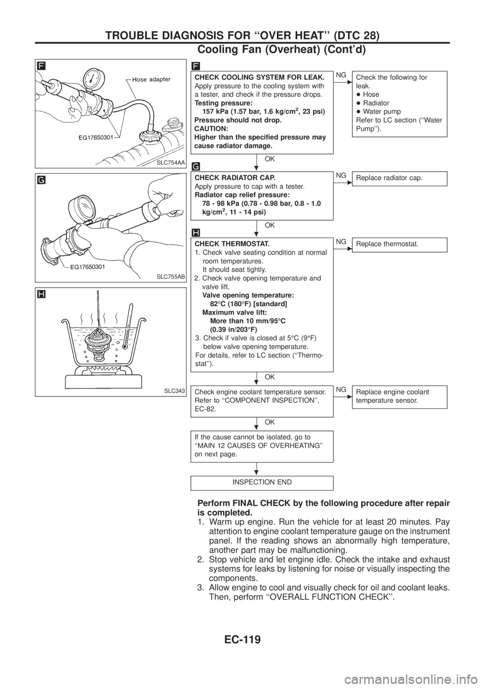
CHECK COOLING SYSTEM FOR LEAK.
Apply pressure to the cooling system with
a tester, and check if the pressure drops.
Testing pressure:
157 kPa (1.57 bar, 1.6 kg/cm
2, 23 psi)
Pressure should not drop.
CAUTION:
Higher than the speci®ed pressure may
cause radiator damage.
OK
cNG
Check the following for
leak.
+Hose
+Radiator
+Water pump
Refer to LC section (``Water
Pump'').
CHECK RADIATOR CAP.
Apply pressure to cap with a tester.
Radiator cap relief pressure:
78 - 98 kPa (0.78 - 0.98 bar, 0.8 - 1.0
kg/cm
2, 11 - 14 psi)
OK
cNG
Replace radiator cap.
CHECK THERMOSTAT.
1. Check valve seating condition at normal
room temperatures.
It should seat tightly.
2. Check valve opening temperature and
valve lift.
Valve opening temperature:
82ÉC (180ÉF) [standard]
Maximum valve lift:
More than 10 mm/95ÉC
(0.39 in/203ÉF)
3. Check if valve is closed at 5ÉC (9ÉF)
below valve opening temperature.
For details, refer to LC section (``Thermo-
stat'').
OK
cNG
Replace thermostat.
Check engine coolant temperature sensor.
Refer to ``COMPONENT INSPECTION'',
EC-82.
OK
cNG
Replace engine coolant
temperature sensor.
If the cause cannot be isolated, go to
``MAIN 12 CAUSES OF OVERHEATING''
on next page.
INSPECTION END
Perform FINAL CHECK by the following procedure after repair
is completed.
1. Warm up engine. Run the vehicle for at least 20 minutes. Pay
attention to engine coolant temperature gauge on the instrument
panel. If the reading shows an abnormally high temperature,
another part may be malfunctioning.
2. Stop vehicle and let engine idle. Check the intake and exhaust
systems for leaks by listening for noise or visually inspecting the
components.
3. Allow engine to cool and visually check for oil and coolant leaks.
Then, perform ``OVERALL FUNCTION CHECK''.
SLC754AA
SLC755AB
SLC343
.
.
.
.
.
TROUBLE DIAGNOSIS FOR ``OVER HEAT'' (DTC 28)
Cooling Fan (Overheat) (Cont'd)
EC-119
Page 273 of 1226
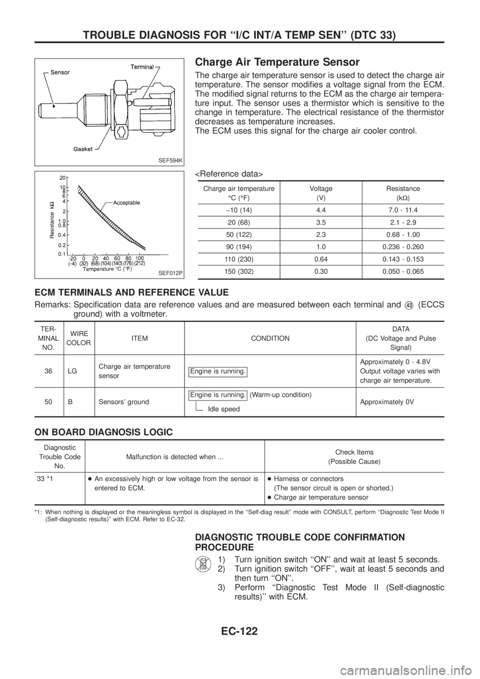
Charge Air Temperature Sensor
The charge air temperature sensor is used to detect the charge air
temperature. The sensor modi®es a voltage signal from the ECM.
The modi®ed signal returns to the ECM as the charge air tempera-
ture input. The sensor uses a thermistor which is sensitive to the
change in temperature. The electrical resistance of the thermistor
decreases as temperature increases.
The ECM uses this signal for the charge air cooler control.
Charge air temperatureÉC (ÉF) Voltage
(V) Resistance
(kW)
þ10 (14) 4.4 7.0 - 11.4 20 (68) 3.5 2.1 - 2.9
50 (122) 2.3 0.68 - 1.00
90 (194) 1.0 0.236 - 0.260
110 (230) 0.64 0.143 - 0.153
150 (302) 0.30 0.050 - 0.065
ECM TERMINALS AND REFERENCE VALUE
Remarks: Speci®cation data are reference values and are measured between each terminal andV43(ECCS
ground) with a voltmeter.
TER-
MINAL NO. WIRE
COLOR ITEM CONDITION DATA
(DC Voltage and Pulse Signal)
36 LG Charge air temperature
sensor Engine is running.
Approximatel
y 0 - 4.8V
Output voltage varies with
charge air temperature.
50 B Sensors' ground Engine is running.
(Warm-up condition)
Idle speed Approximately 0V
ON BOARD DIAGNOSIS LOGIC
Diagnostic
Trouble Code No. Malfunction is detected when ...
Check Items
(Possible Cause)
33 *1 +An excessively high or low voltage from the sensor is
entered to ECM. +
Harness or connectors
(The sensor circuit is open or shorted.)
+ Charge air temperature sensor
*1: When nothing is displayed or the meaningless symbol is displayed in the ``Self-diag result'' mode with CONSULT, perform ``Diagnostic Test Mode II
(Self-diagnostic results)'' with ECM. Refer to EC-32.
DIAGNOSTIC TROUBLE CODE CONFIRMATION
PROCEDURE
1) Turn ignition switch ``ON'' and wait at least 5 seconds.
2) Turn ignition switch ``OFF'', wait at least 5 seconds and then turn ``ON''.
3) Perform ``Diagnostic Test Mode II (Self-diagnostic results)'' with ECM.
SEF594K
SEF012P
TROUBLE DIAGNOSIS FOR ``I/C INT/A TEMP SEN'' (DTC 33)
EC-122