2006 NISSAN PATROL air condition
[x] Cancel search: air conditionPage 525 of 1226
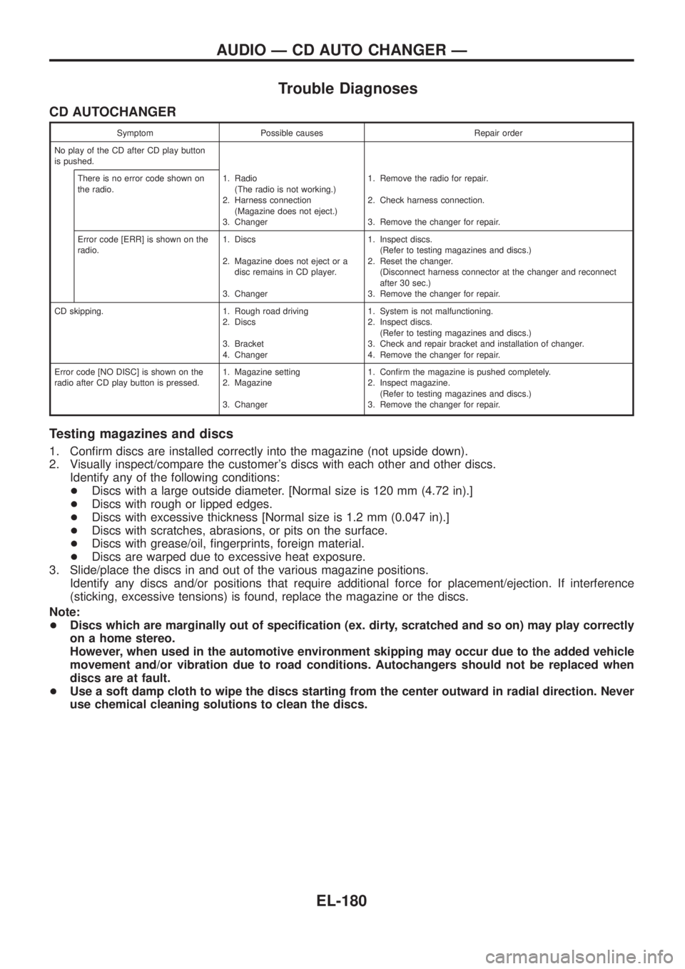
Trouble Diagnoses
CD AUTOCHANGER
Symptom Possible causes Repair order
No play of the CD after CD play button
is pushed.
There is no error code shown on
the radio.1. Radio
(The radio is not working.)
2. Harness connection
(Magazine does not eject.)
3. Changer1. Remove the radio for repair.
2. Check harness connection.
3. Remove the changer for repair.
Error code [ERR] is shown on the
radio.1. Discs
2. Magazine does not eject or a
disc remains in CD player.
3. Changer1. Inspect discs.
(Refer to testing magazines and discs.)
2. Reset the changer.
(Disconnect harness connector at the changer and reconnect
after 30 sec.)
3. Remove the changer for repair.
CD skipping. 1. Rough road driving
2. Discs
3. Bracket
4. Changer1. System is not malfunctioning.
2. Inspect discs.
(Refer to testing magazines and discs.)
3. Check and repair bracket and installation of changer.
4. Remove the changer for repair.
Error code [NO DISC] is shown on the
radio after CD play button is pressed.1. Magazine setting
2. Magazine
3. Changer1. Con®rm the magazine is pushed completely.
2. Inspect magazine.
(Refer to testing magazines and discs.)
3. Remove the changer for repair.
Testing magazines and discs
1. Con®rm discs are installed correctly into the magazine (not upside down).
2. Visually inspect/compare the customer's discs with each other and other discs.
Identify any of the following conditions:
+Discs with a large outside diameter. [Normal size is 120 mm (4.72 in).]
+Discs with rough or lipped edges.
+Discs with excessive thickness [Normal size is 1.2 mm (0.047 in).]
+Discs with scratches, abrasions, or pits on the surface.
+Discs with grease/oil, ®ngerprints, foreign material.
+Discs are warped due to excessive heat exposure.
3. Slide/place the discs in and out of the various magazine positions.
Identify any discs and/or positions that require additional force for placement/ejection. If interference
(sticking, excessive tensions) is found, replace the magazine or the discs.
Note:
+Discs which are marginally out of speci®cation (ex. dirty, scratched and so on) may play correctly
on a home stereo.
However, when used in the automotive environment skipping may occur due to the added vehicle
movement and/or vibration due to road conditions. Autochangers should not be replaced when
discs are at fault.
+Use a soft damp cloth to wipe the discs starting from the center outward in radial direction. Never
use chemical cleaning solutions to clean the discs.
AUDIO Ð CD AUTO CHANGER Ð
EL-180
Page 554 of 1226
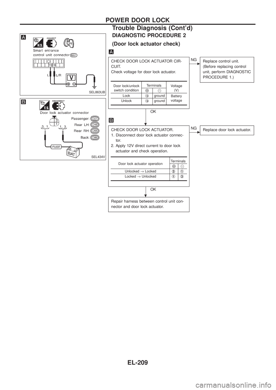
DIAGNOSTIC PROCEDURE 2
(Door lock actuator check)
CHECK DOOR LOCK ACTUATOR CIR-
CUIT.
Check voltage for door lock actuator.
OK
cNG
Replace control unit.
(Before replacing control
unit, perform DIAGNOSTIC
PROCEDURE 1.)
CHECK DOOR LOCK ACTUATOR.
1. Disconnect door lock actuator connec-
tor.
2. Apply 12V direct current to door lock
actuator and check operation.
OK
cNG
Replace door lock actuator.
Repair harness between control unit con-
nector and door lock actuator.
Door lock/unlock
switch conditionTerminals
Voltage
(V)
Å@
Lockj
15ground
Battery
voltage
Unlockj
16ground
Door lock actuator operationTerminalsÅ@
Unlocked®Lockedj
3j1
Locked®Unlockedj1j3
SEL863UB
SEL434V
.
.
POWER DOOR LOCK
Trouble Diagnosis (Cont'd)
EL-209
Page 576 of 1226
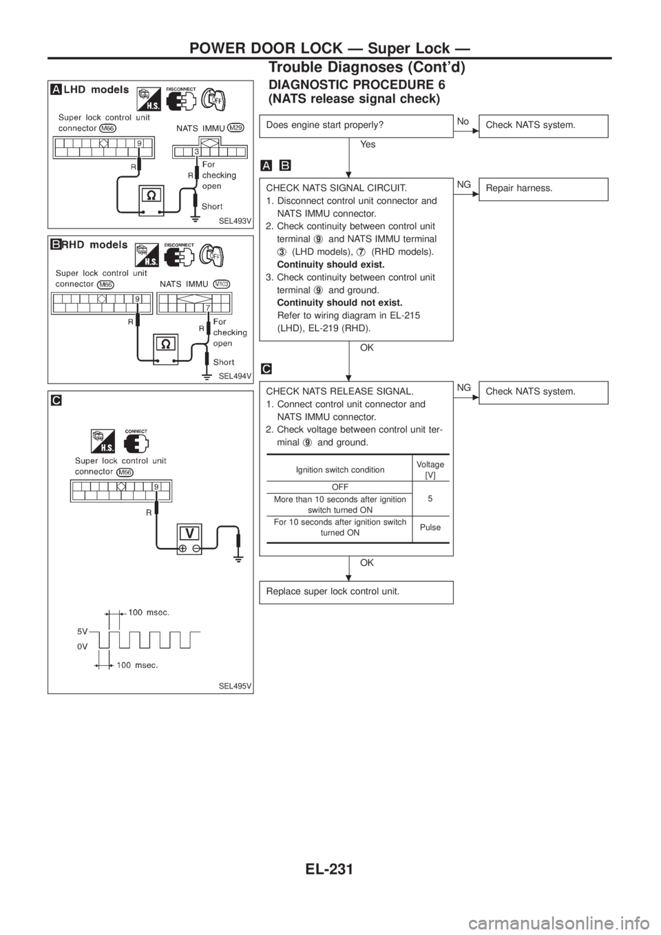
DIAGNOSTIC PROCEDURE 6
(NATS release signal check)
Does engine start properly?
Ye s
cNo
Check NATS system.
CHECK NATS SIGNAL CIRCUIT.
1. Disconnect control unit connector and
NATS IMMU connector.
2. Check continuity between control unit
terminalj
9and NATS IMMU terminal
j
3(LHD models),j7(RHD models).
Continuity should exist.
3. Check continuity between control unit
terminalj
9and ground.
Continuity should not exist.
Refer to wiring diagram in EL-215
(LHD), EL-219 (RHD).
OK
cNG
Repair harness.
CHECK NATS RELEASE SIGNAL.
1. Connect control unit connector and
NATS IMMU connector.
2. Check voltage between control unit ter-
minalj
9and ground.
OK
cNG
Check NATS system.
Replace super lock control unit.
Ignition switch conditionVoltage
[V]
OFF
5
More than 10 seconds after ignition
switch turned ON
For 10 seconds after ignition switch
turned ONPulse
SEL493V
SEL494V
SEL495V
.
.
.
POWER DOOR LOCK Ð Super Lock Ð
Trouble Diagnoses (Cont'd)
EL-231
Page 660 of 1226

Use the chart below to ®nd out what each wiring diagram code
stands for.
Code Section Wiring Diagram Name
A/C,A HA Auto Air Conditioner
A/C CUT EC Air Conditioner Cut Control
A/C,M HA Manual Air Conditioner
A/T AT A/T
AAC/V EC IACV-AAC Valve
ABS BR Anti-lock Brake System
ACC/SW EC Accelerator Switch (FC)
ACL/SW EC Accelerator Position Switch
ADJRES EC Adjustment Resistor
APS EC Accelerator Position Sensor
ASCD EL Automatic Speed Control Device
AT/C EC A/T Control
AUDIO EL Audio
BACK/L EL Back-up Lamp
BCDD EC BCDD System
CD/CHG EL CD Auto Changer
CHARGE EL Charging System
CHIME EL Warning Chime
CHOKE EC Automatic Choke
CIGAR EL Cigarette Lighter
CKPS EC Crankshaft Position Sensor (OBD)
CLOCK EL Clock
CMPS EC Camshaft Position Sensor
COMPAS EL Compass and Thermometer
COOL/B HA Cool Box
COOL/F EC Cooling Fan Control
CORNER EL Cornering Lamp
CSPS EC Control Sleeve Position Sensor
D/LOCK EL Power Door Lock
DEICER EL Wiper Deicer
DEF EL Rear Window Defogger
DIFF/L PD Differential Lock Control System
DTRL ELHeadlamp Ð With Daytime Light
System
ECTS EC Engine Coolant Temperature Sensor
EGRC/V EC EGRC-Solenoid Valve
F/FOG EL Front Fog Lamp
F/PUMP EC Fuel Pump
FCUT EC Fuel Cut Solenoid Valve
FICD EC IACV-FICD Solenoid Valve
FTS EC Fuel Temperature SensorCode Section Wiring Diagram Name
GLOW EC Quick Glow System
GOVNR EC Electric Governor
H/AIM EL Headlamp Aiming Control System
H/LAMP EL Headlamp
HEATUP EC Heat up Switch
HLC EL Headlamp Cleaner
HORN EL Horn
HSEAT EL Heated Seat
IATS EC Intake Air Temperature Sensor
IC/FAN EC Charge Air Cooler Fan
IGN EC Ignition System
IGN/SG EC Ignition Signal
ILL EL Illumination
INJECT EC Injector
INT/L EL Spot, Vanity Mirror Lamps
KS EC Knock Sensor
MAFS EC Mass Air Flow Sensor
MAIN ECMain Power Supply and Ground Cir-
cuit
METER ELSpeedometer, Tachometer, Temp.,
Oil and Fuel Gauges
MIL/DL EC Mil and Data Link Connectors
MIRROR EL Door Mirror
MULTI EL Multi-remote Control System
NATS EL Nissan Anti-Theft System
NLS EC Needle Lift Sensor
P/ANT EL Power Antenna
PLA EC Partial Load Advance Control
PNP/SW EC Park/Neutral Position Switch
POWER EL Power Supply Routing
PST/SW EC Power Steering Oil Pressure Switch
R/COOL HA Rear Cooler System
R/FOG EL Rear Fog Lamp
R/HEAT HA Rear Heater System
ROOM/L EL Interior Room Lamp
S/LOCK EL Power Door Lock Ð Super Lock
S/SIG EC Start Signal
S/TANK FE Sub Fuel Tank Control System
SEAT EL Power Seat
SROOF EL Sunroof
SRS RS Supplemental Restraint System
WIRING DIAGRAM CODES (CELL CODES)
EL-315
Page 676 of 1226
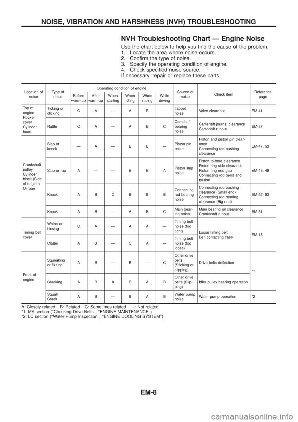
NVH Troubleshooting Chart Ð Engine Noise
Use the chart below to help you ®nd the cause of the problem.
1. Locate the area where noise occurs.
2. Con®rm the type of noise.
3. Specify the operating condition of engine.
4. Check speci®ed noise source.
If necessary, repair or replace these parts.
Location of
noiseType of
noiseOperating condition of engine
Source of
noiseCheck itemReference
page Before
warm-upAfter
warm-upWhen
startingWhen
idlingWhen
racingWhile
driving
To p o f
engine
Rocker
cover
Cylinder
headTicking or
clickingCAÐABÐTappet
noiseValve clearance EM-41
Rattle C A Ð A B CCamshaft
bearing
noiseCamshaft journal clearance
Camshaft runoutEM-37
Crankshaft
pulley
Cylinder
block (Side
of engine)
Oil panSlap or
knockÐAÐB BÐPiston pin
noisePiston and piston pin clear-
ance
Connecting rod bushing
clearanceEM-47, 53
Slap or rap A Ð Ð B B APiston slap
noisePiston-to-bore clearance
Piston ring side clearance
Piston ring end gap
Connecting rod bend and
torsionEM-48, 49
Knock A B C B B BConnecting
rod bearing
noiseConnecting rod bushing
clearance (Small end)
Connecting rod bearing
clearance (Big end)EM-52, 53
Knock A B Ð A B CMain bear-
ing noiseMain bearing oil clearance
Crankshaft runoutEM-51
Timing belt
coverWhine or
hissingCAÐAAÐTiming belt
noise (too
tight)
Loose timing belt
Belt contacting caseEM-18
Clatter A B Ð C A ÐTiming belt
noise (too
loose)
Front of
engineSqueaking
or ®zzingABÐBÐCOther drive
belts
(Sticking or
slipping)Drive belts de¯ection
*1
CreakingABABABOther drive
belts (Slip-
ping)Idler pulley bearing operation
Squall
CreakABÐBABWater pump
noiseWater pump operation *2
A: Closely related B: Related C: Sometimes related Ð: Not related
*1: MA section (``Checking Drive Belts'', ``ENGINE MAINTENANCE'')
*2: LC section (``Water Pump Inspection'', ``ENGINE COOLING SYSTEM'')
NOISE, VIBRATION AND HARSHNESS (NVH) TROUBLESHOOTING
EM-8
Page 713 of 1226
Removal
1. Remove engine, transmission and transfer's undercovers, oil
pan guard and hood.
2. Drain engine coolant.
3. Remove charge air cooler assembly.
4. Remove vacuum hoses, fuel tubes, harnesses, and connectors
and so on.
5. Remove radiator assembly.
6. Remove drive belts.
7. Remove power steering oil pump, alternator and air conditioner
compressor.
8. Remove starter motor assembly.
9. Remove front exhaust tube.
10. Remove transmission from vehicle.
Refer to MT section.
11. Hoist engine with engine slingers and remove engine mounting
bolts from both sides.
12. Remove engine from vehicle.
Installation
+Install in reverse order of removal.
ENGINE REMOVAL
EM-45
Page 773 of 1226
GENERAL INFORMATION
SECTION
GI
CONTENTS
PRECAUTIONS...............................................................1
Precaution for Supplemental Restraint System
(SRS) ``AIR BAG'' and ``SEAT BELT
PRE-TENSIONER'' ......................................................1
General Precautions ....................................................2
Precautions for Multiport Fuel Injection System
or ECCS Engine ..........................................................3
Precautions for Three Way Catalyst
(If so equipped)............................................................4
Precautions for Engine Oils .........................................4
Precautions for Fuel ....................................................5
Precautions for Air Conditioning ..................................5
HOW TO USE THIS MANUAL........................................6
HOW TO READ WIRING DIAGRAMS............................8
Sample/Wiring Diagram Ð EXAMPL Ð......................8
Description .................................................................10
HOW TO CHECK TERMINAL.......................................17
How to Probe Connectors .........................................17
How to Check Enlarged Contact Spring of
Terminal .....................................................................18
Waterproof Connector Inspection ..............................19
Terminal Lock Inspection ...........................................19
HOW TO PERFORM EFFICIENT DIAGNOSIS FOR
AN ELECTRICAL INCIDENT........................................20Work Flow ..................................................................20
Incident Simulation Tests ...........................................21
Circuit Inspection .......................................................24
HOW TO FOLLOW FLOW CHART IN TROUBLE
DIAGNOSES..................................................................30
How to Follow This Flow Chart .................................31
CONSULT CHECKING SYSTEM..................................33
Function and System Application ..............................33
Lithium Battery Replacement ....................................33
Checking Equipment..................................................33
Loading Procedure ....................................................34
CONSULT Data Link Connector (DLC) Circuit..........34
IDENTIFICATION INFORMATION.................................35
Model Variation ..........................................................35
Identi®cation Number .................................................36
Dimensions ................................................................38
Wheels & Tires ..........................................................38
LIFTING POINTS AND TOW TRUCK TOWING...........39
Screw Jack ................................................................39
Garage Jack and Safety Stand .................................39
2-pole Lift ...................................................................40
Tow Truck Towing ......................................................41
SAE J1930 TERMINOLOGY LIST................................43
SAE J1930 Terminology List .....................................43
GI
Page 778 of 1226
Dispose of used oil and used oil ®lters through authorized waste
disposal contractors to licensed waste disposal sites, or to the
waste oil reclamation trade. If in doubt, contact the local authority
for advice on disposal facilities.
It is illegal to pour used oil on to the ground, down sewers or drains,
or into water courses.
The regulations concerning the pollution of the environment
will vary from country to country.
Precautions for Fuel
GASOLINE ENGINE:
Three way catalyst equipped models ... unleaded gasoline of at
least 91 octane (RON)
CAUTION:
Do not use leaded gasoline. Using leaded gasoline will dam-
age the three way catalyst.
Except for the above models ... unleaded or leaded gasoline of
above 88 octane (RON)
Use unleaded fuel if instructed on the fuel ®ller lid.
DIESEL ENGINE*:
Diesel fuel of above 45 cetane for TD42 engine and above 50 cet-
ane for RD28ET engine
* If two types of diesel fuel are available, use summer or winter
fuel properly according to the following temperature conditions.
+Above þ7ÉC (20ÉF) ... Summer type diesel fuel.
+Below þ7ÉC (20ÉF) ... Winter type diesel fuel.
CAUTION:
+Do not use home heating oil, gasoline, or other alternate
fuels in your diesel engine. The use of those can cause
engine damage.
+Do not use summer fuel at temperature below þ7ÉC (20ÉF).
The cold temperature will cause wax to form in the fuel. As
a result, it may prevent the engine from running smoothly.
+Do not add gasoline or other alternate fuels to diesel fuel.
Precautions for Air Conditioning
Use an approved refrigerant recovery unit any time the air condi-
tioning system must be discharged. Refer to HA section (``HFC-
134a (R-134a) Service Procedure'', ``SERVICE PROCEDURES'')
for speci®c instructions.
PRECAUTIONS
Precautions for Engine Oils (Cont'd)
GI-5