Page 1164 of 1226

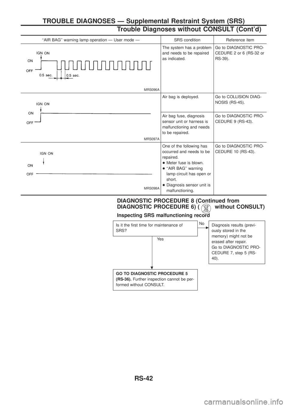
``AIR BAG'' warning lamp operation Ð User mode Ð SRS condition Reference item
MRS096A
The system has a problem
and needs to be repaired
as indicated.Go to DIAGNOSTIC PRO-
CEDURE 2 or 6 (RS-32 or
RS-39).
MRS097A
Air bag is deployed. Go to COLLISION DIAG-
NOSIS (RS-45).
Air bag fuse, diagnosis
sensor unit or harness is
malfunctioning and needs
to be repaired.Go to DIAGNOSTIC PRO-
CEDURE 9 (RS-43).
MRS098A
One of the following has
occurred and needs to be
repaired.
+Meter fuse is blown.
+``AIR BAG'' warning
lamp circuit has open or
short.
+Diagnosis sensor unit is
malfunctioning.Go to DIAGNOSTIC PRO-
CEDURE 10 (RS-43).
DIAGNOSTIC PROCEDURE 8 (Continued from
DIAGNOSTIC PROCEDURE 6) (
without CONSULT)
Inspecting SRS malfunctioning record
Is it the ®rst time for maintenance of
SRS?
Ye s
cNo
Diagnosis results (previ-
ously stored in the
memory) might not be
erased after repair.
Go to DIAGNOSTIC PRO-
CEDURE 7, step 5 (RS-
40).
GO TO DIAGNOSTIC PROCEDURE 5
(RS-36).Further inspection cannot be per-
formed without CONSULT.
.
TROUBLE DIAGNOSES Ð Supplemental Restraint System (SRS)
Trouble Diagnoses without CONSULT (Cont'd)
RS-42
Page 1166 of 1226
Trouble Diagnoses: SRS Does Not Enter
Diagnosis Mode Using Door Switch
DIAGNOSTIC PROCEDURE 11
Disconnect both battery cables and check
battery voltage using circuit tester.
+Is battery voltage more than 9V?
Ye s
cNo
Charge battery.
Remove driver's door switch and check
continuity between driver's door switch
connector terminals
V1andV3under the
following conditions.
Ye s
cNo
Replace driver's door
switch.
Check harness continuity between driver's
door switch connector terminal
V3and
body ground.
+Does continuity exist?
Ye s
cNo
Replace or repair harness.
Replace diagnosis sensor unit.
Go to SRS Operation Check (RS-30).
Condition Continuity
Door switch is depressed
(Door is closed).NO
Door switch is released
(Door is open).YES
SRS263
SRS470
SRS265-D
.
.
.
.
TROUBLE DIAGNOSES Ð Supplemental Restraint System (SRS)
RS-44
Page 1219 of 1226
AIR BREATHER
+Install as shown in illustration.
Thread locker:
Refer to TF-10.
Shift Control Components
INSPECTION
+Check contact surface and sliding surface for wear, scratches,
projections or other faulty conditions.
L & H SHIFT ROD & FORK
+Assemble as shown in illustration.
* This pin is the same size as the one for 2-4 shift rod.
2-4 SHIFT ROD & FORK
+Assemble as shown in illustration.
* These pins are the same size.
+Pay attention to the direction of fork guide collar.
SMT148B
SMT360A
SMT149B
SMT150B
SMT033B
REPAIR FOR COMPONENT PARTS
TF-26