2006 NISSAN PATROL air condition
[x] Cancel search: air conditionPage 780 of 1226
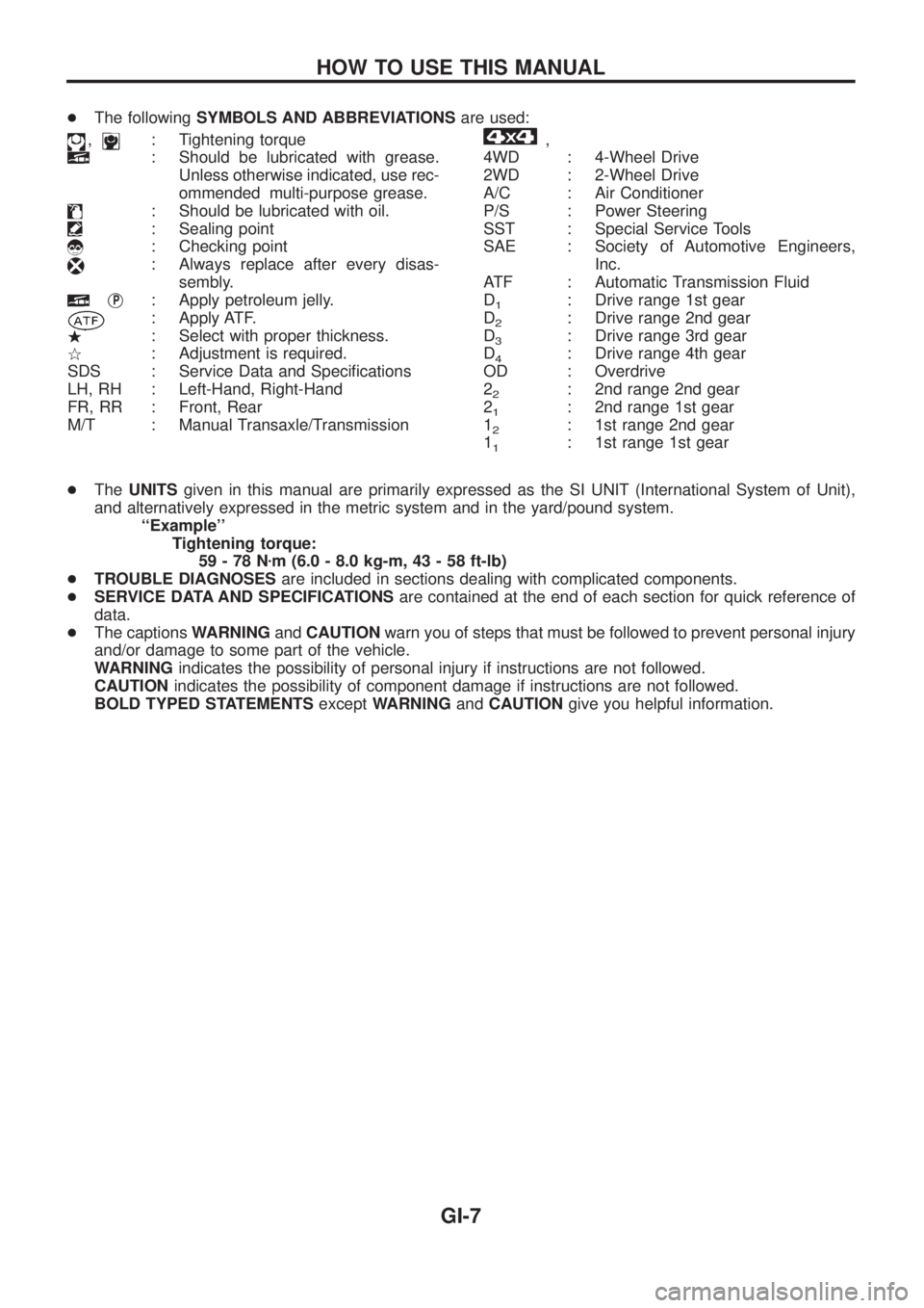
+The followingSYMBOLS AND ABBREVIATIONSare used:
,: Tightening torque
: Should be lubricated with grease.
Unless otherwise indicated, use rec-
ommended multi-purpose grease.
: Should be lubricated with oil.
: Sealing point
: Checking point
: Always replace after every disas-
sembly.
jP: Apply petroleum jelly.
: Apply ATF.
.: Select with proper thickness.
>: Adjustment is required.
SDS : Service Data and Speci®cations
LH, RH : Left-Hand, Right-Hand
FR, RR : Front, Rear
M/T : Manual Transaxle/Transmission
,
4WD : 4-Wheel Drive
2WD : 2-Wheel Drive
A/C : Air Conditioner
P/S : Power Steering
SST : Special Service Tools
SAE : Society of Automotive Engineers,
Inc.
ATF : Automatic Transmission Fluid
D
1: Drive range 1st gear
D
2: Drive range 2nd gear
D
3: Drive range 3rd gear
D
4: Drive range 4th gear
OD : Overdrive
2
2: 2nd range 2nd gear
2
1: 2nd range 1st gear
1
2: 1st range 2nd gear
1
1: 1st range 1st gear
+TheUNITSgiven in this manual are primarily expressed as the SI UNIT (International System of Unit),
and alternatively expressed in the metric system and in the yard/pound system.
``Example''
Tightening torque:
59-78Nzm (6.0 - 8.0 kg-m, 43 - 58 ft-lb)
+TROUBLE DIAGNOSESare included in sections dealing with complicated components.
+SERVICE DATA AND SPECIFICATIONSare contained at the end of each section for quick reference of
data.
+The captionsWARNINGandCAUTIONwarn you of steps that must be followed to prevent personal injury
and/or damage to some part of the vehicle.
WARNINGindicates the possibility of personal injury if instructions are not followed.
CAUTIONindicates the possibility of component damage if instructions are not followed.
BOLD TYPED STATEMENTSexceptWARNINGandCAUTIONgive you helpful information.
HOW TO USE THIS MANUAL
GI-7
Page 793 of 1226
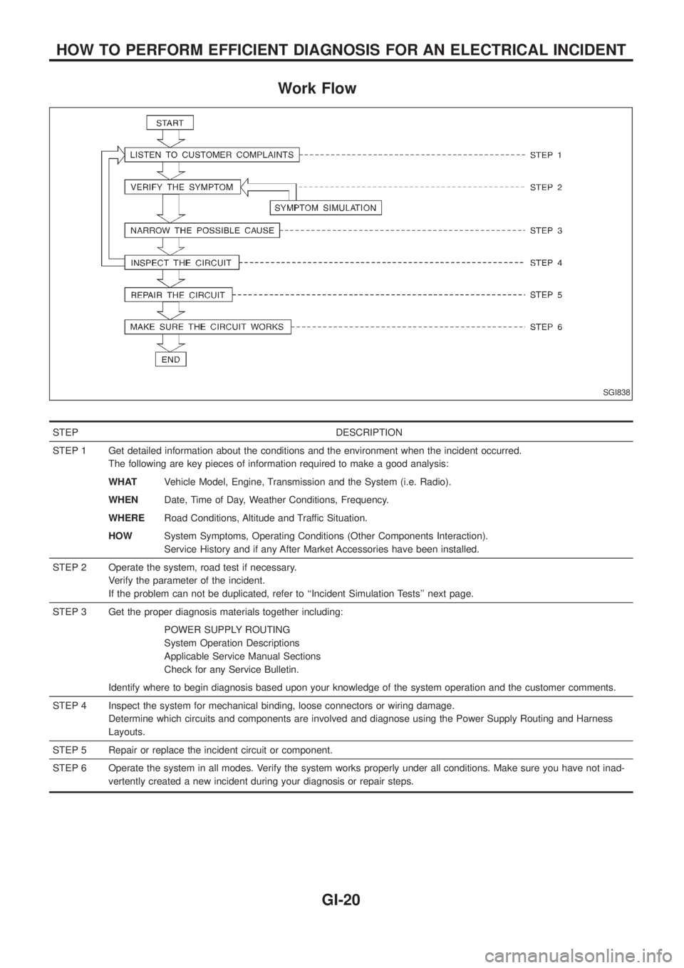
Work Flow
STEP DESCRIPTION
STEP 1 Get detailed information about the conditions and the environment when the incident occurred.
The following are key pieces of information required to make a good analysis:
WHATVehicle Model, Engine, Transmission and the System (i.e. Radio).
WHENDate, Time of Day, Weather Conditions, Frequency.
WHERERoad Conditions, Altitude and Traffic Situation.
HOWSystem Symptoms, Operating Conditions (Other Components Interaction).
Service History and if any After Market Accessories have been installed.
STEP 2 Operate the system, road test if necessary.
Verify the parameter of the incident.
If the problem can not be duplicated, refer to ``Incident Simulation Tests'' next page.
STEP 3 Get the proper diagnosis materials together including:
POWER SUPPLY ROUTING
System Operation Descriptions
Applicable Service Manual Sections
Check for any Service Bulletin.
Identify where to begin diagnosis based upon your knowledge of the system operation and the customer comments.
STEP 4 Inspect the system for mechanical binding, loose connectors or wiring damage.
Determine which circuits and components are involved and diagnose using the Power Supply Routing and Harness
Layouts.
STEP 5 Repair or replace the incident circuit or component.
STEP 6 Operate the system in all modes. Verify the system works properly under all conditions. Make sure you have not inad-
vertently created a new incident during your diagnosis or repair steps.
SGI838
HOW TO PERFORM EFFICIENT DIAGNOSIS FOR AN ELECTRICAL INCIDENT
GI-20
Page 820 of 1226
HEATER &
AIR CONDITIONER
SECTION
HA
CONTENTS
MANUAL AND AUTO
PRECAUTIONS AND PREPARATION............................1
Supplemental Restraint System (SRS) ``AIR
BAG'' and ``SEAT BELT PRE-TENSIONER'' ...............1
Precautions for Working with HFC-134a (R-134a) .....1
General Refrigerant Precautions .................................2
Precautions for Refrigerant Connection ......................2
Precautions for Servicing Compressor ........................6
Special Service Tools ..................................................6
HFC-134a (R-134a) Service Tools and
Equipment ....................................................................7
Precautions for Service Equipment .............................9
DESCRIPTION............................................................... 11
Refrigeration Cycle .................................................... 11
Component Layout ....................................................12
Discharge Air Flow.....................................................13
REAR HEATER
TROUBLE DIAGNOSES...............................................14
Wiring Diagram Ð R/HEAT Ð/LHD Models .............14
Wiring Diagram Ð R/HEAT Ð/RHD Models .............15
MANUAL
DESCRIPTION...............................................................16
System Description ....................................................16
Control Operation ......................................................16
TROUBLE DIAGNOSES...............................................17
Component Location..................................................17
Wiring Diagram Ð A/C, M Ð ....................................19
How to Perform Trouble Diagnoses for Quick
and Accurate Repair ..................................................21
Operational Check .....................................................22
Intake Door Motor ......................................................24
Blower Motor..............................................................28
Insufficient Cooling ....................................................32
Trouble Diagnoses for Abnormal Pressure ...............36
Insufficient Heating ....................................................39Air Outlet ....................................................................41
Magnet Clutch............................................................43
Noise ..........................................................................48
AUTO
DESCRIPTION...............................................................49
Introduction ................................................................49
Features .....................................................................49
Overview of Control System ......................................52
Control Operation ......................................................53
TROUBLE DIAGNOSES...............................................55
Component Location..................................................55
Circuit Diagram ..........................................................57
Wiring Diagram Ð A/C, A Ð .....................................58
Auto Amp. Terminals and Reference Value...............61
Self-diagnosis ............................................................63
How to Perform Trouble Diagnoses for Quick
and Accurate Repair ..................................................69
Operational Check .....................................................70
A/C System ................................................................73
Mode Door Motor.......................................................75
Air Mix Door Motor ....................................................79
Intake Door Motor ......................................................82
Blower Motor..............................................................86
Magnet Clutch............................................................92
Insufficient Cooling ....................................................98
Insufficient Heating ....................................................99
Noise ........................................................................100
Self-diagnosis ..........................................................101
Memory Function .....................................................102
Ambient Sensor .......................................................103
In-vehicle Sensor .....................................................105
Sunload Sensor .......................................................107
Intake Sensor........................................................... 110
HA
Page 823 of 1226
General Refrigerant Precautions
WARNING:
+Do not release refrigerant into the air. Use approved recovery/recycling equipment to capture the
refrigerant every time an air conditioning system is discharged.
+Always wear eye and hand protection (goggles and gloves) when working with any refrigerant or
air conditioning system.
+Do not store or heat refrigerant containers above 52ÉC.
+Do not heat a refrigerant container with an open ¯ame; if container warming is required, place the
bottom of the container in a warm pail of water.
+Do not intentionally drop, puncture, or incinerate refrigerant containers.
+Keep refrigerant away from open ¯ames: poisonous gas will be produced if refrigerant burns.
+Refrigerant will displace oxygen, therefore be certain to work in well ventilated areas to prevent
suffocation.
+Do not introduce compressed air to any refrigerant container or refrigerant component.
Precautions for Refrigerant Connection
A new type refrigerant connection has been introduced to all refrigerant lines except the following location.
+Expansion valve to cooling unit
+A part of high-pressure line
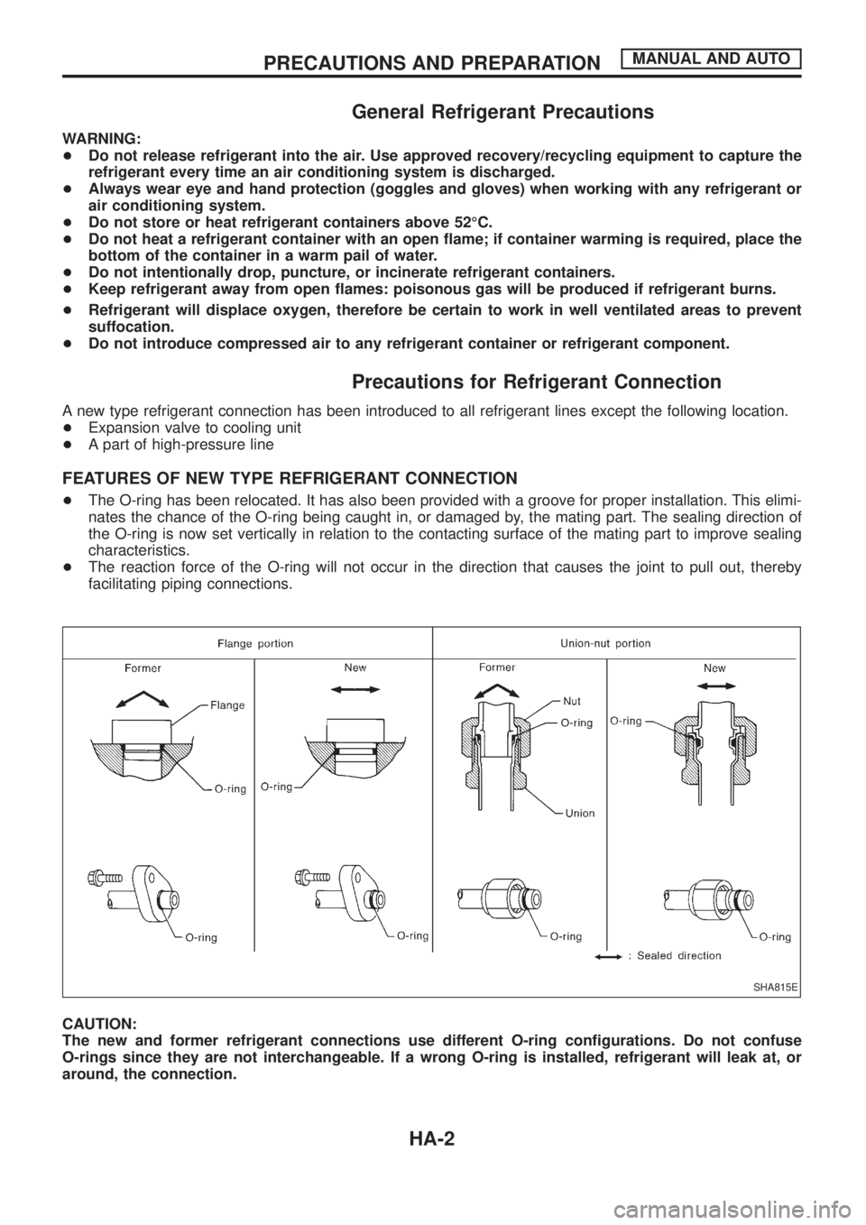
FEATURES OF NEW TYPE REFRIGERANT CONNECTION
+The O-ring has been relocated. It has also been provided with a groove for proper installation. This elimi-
nates the chance of the O-ring being caught in, or damaged by, the mating part. The sealing direction of
the O-ring is now set vertically in relation to the contacting surface of the mating part to improve sealing
characteristics.
+The reaction force of the O-ring will not occur in the direction that causes the joint to pull out, thereby
facilitating piping connections.
CAUTION:
The new and former refrigerant connections use different O-ring con®gurations. Do not confuse
O-rings since they are not interchangeable. If a wrong O-ring is installed, refrigerant will leak at, or
around, the connection.
SHA815E
PRECAUTIONS AND PREPARATIONMANUAL AND AUTO
HA-2
Page 826 of 1226
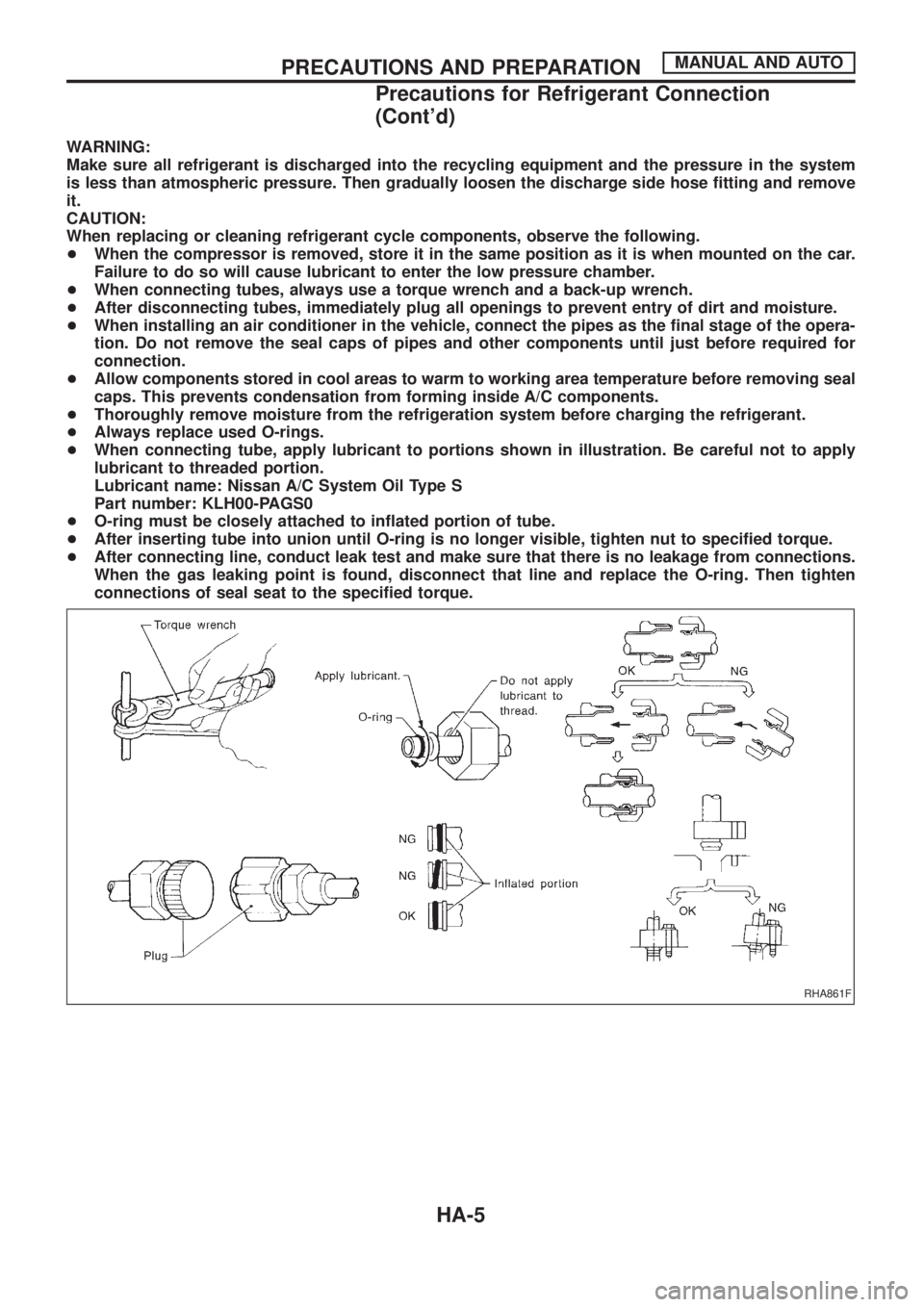
WARNING:
Make sure all refrigerant is discharged into the recycling equipment and the pressure in the system
is less than atmospheric pressure. Then gradually loosen the discharge side hose ®tting and remove
it.
CAUTION:
When replacing or cleaning refrigerant cycle components, observe the following.
+When the compressor is removed, store it in the same position as it is when mounted on the car.
Failure to do so will cause lubricant to enter the low pressure chamber.
+When connecting tubes, always use a torque wrench and a back-up wrench.
+After disconnecting tubes, immediately plug all openings to prevent entry of dirt and moisture.
+When installing an air conditioner in the vehicle, connect the pipes as the ®nal stage of the opera-
tion. Do not remove the seal caps of pipes and other components until just before required for
connection.
+Allow components stored in cool areas to warm to working area temperature before removing seal
caps. This prevents condensation from forming inside A/C components.
+Thoroughly remove moisture from the refrigeration system before charging the refrigerant.
+Always replace used O-rings.
+When connecting tube, apply lubricant to portions shown in illustration. Be careful not to apply
lubricant to threaded portion.
Lubricant name: Nissan A/C System Oil Type S
Part number: KLH00-PAGS0
+O-ring must be closely attached to in¯ated portion of tube.
+After inserting tube into union until O-ring is no longer visible, tighten nut to speci®ed torque.
+After connecting line, conduct leak test and make sure that there is no leakage from connections.
When the gas leaking point is found, disconnect that line and replace the O-ring. Then tighten
connections of seal seat to the speci®ed torque.
RHA861F
PRECAUTIONS AND PREPARATIONMANUAL AND AUTO
Precautions for Refrigerant Connection
(Cont'd)
HA-5
Page 837 of 1226
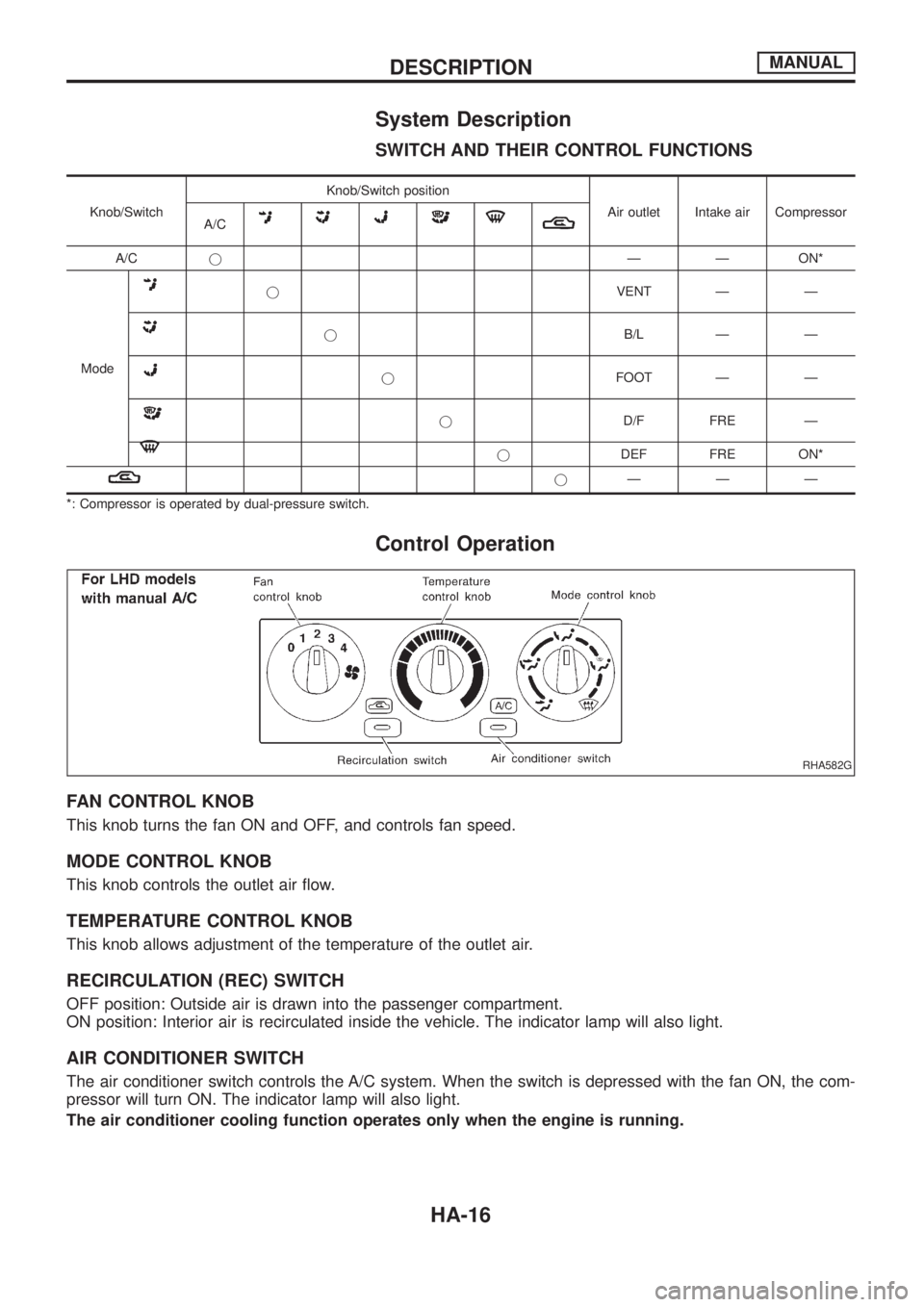
System Description
SWITCH AND THEIR CONTROL FUNCTIONS
Knob/SwitchKnob/Switch position
Air outlet Intake air Compressor
A/C
A/CjÐ Ð ON*
Mode
jVENT Ð Ð
jB/L Ð Ð
jFOOT Ð Ð
jD/F FRE Ð
jDEF FRE ON*
jÐÐÐ
*: Compressor is operated by dual-pressure switch.
Control Operation
FAN CONTROL KNOB
This knob turns the fan ON and OFF, and controls fan speed.
MODE CONTROL KNOB
This knob controls the outlet air ¯ow.
TEMPERATURE CONTROL KNOB
This knob allows adjustment of the temperature of the outlet air.
RECIRCULATION (REC) SWITCH
OFF position: Outside air is drawn into the passenger compartment.
ON position: Interior air is recirculated inside the vehicle. The indicator lamp will also light.
AIR CONDITIONER SWITCH
The air conditioner switch controls the A/C system. When the switch is depressed with the fan ON, the com-
pressor will turn ON. The indicator lamp will also light.
The air conditioner cooling function operates only when the engine is running.
RHA582G
DESCRIPTIONMANUAL
HA-16
Page 843 of 1226
Operational Check
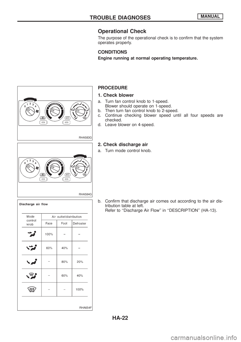
The purpose of the operational check is to con®rm that the system
operates properly.
CONDITIONS
Engine running at normal operating temperature.
PROCEDURE
1. Check blower
a. Turn fan control knob to 1-speed.
Blower should operate on 1-speed.
b. Then turn fan control knob to 2-speed.
c. Continue checking blower speed until all four speeds are
checked.
d. Leave blower on 4-speed.
2. Check discharge air
a. Turn mode control knob.
b. Con®rm that discharge air comes out according to the air dis-
tribution table at left.
Refer to ``Discharge Air Flow'' in ``DESCRIPTION'' (HA-13).
RHA583G
RHA584G
RHA654F
TROUBLE DIAGNOSESMANUAL
HA-22
Page 844 of 1226
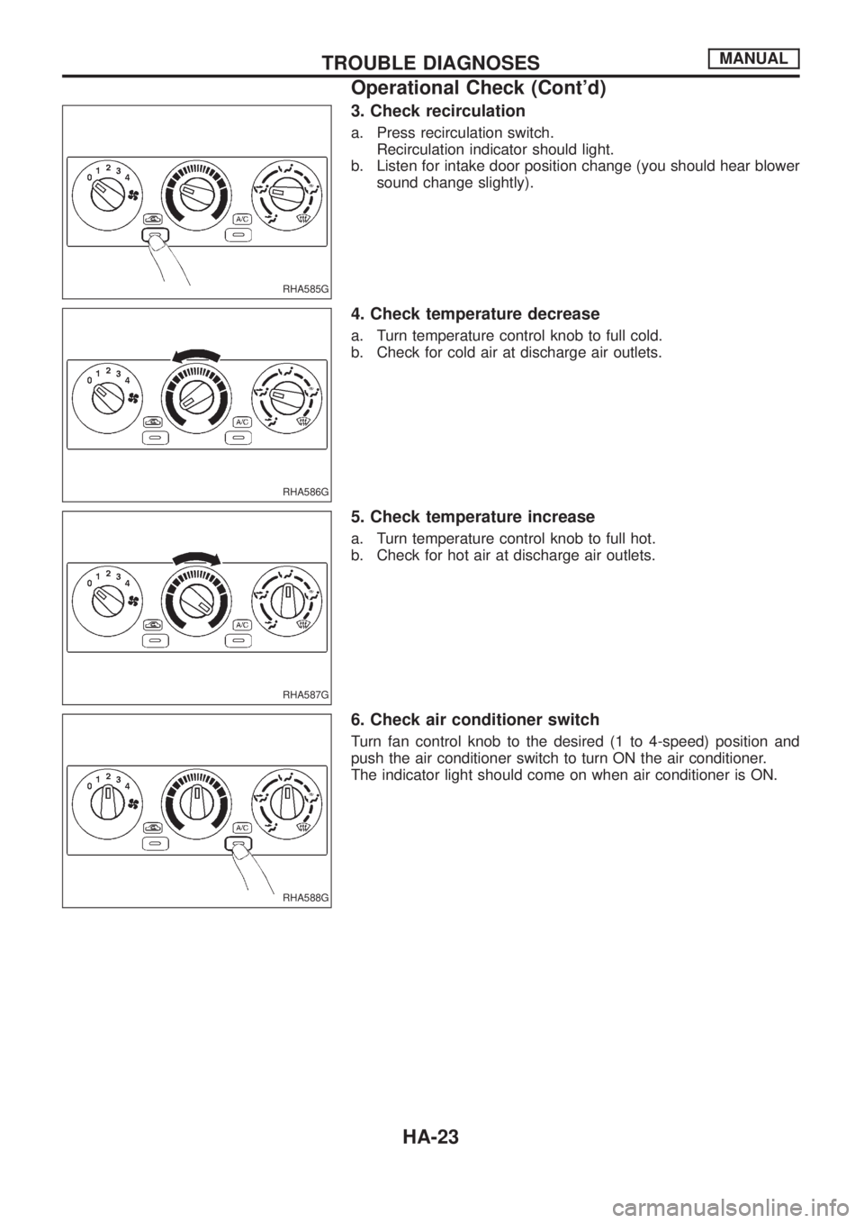
3. Check recirculation
a. Press recirculation switch.
Recirculation indicator should light.
b. Listen for intake door position change (you should hear blower
sound change slightly).
4. Check temperature decrease
a. Turn temperature control knob to full cold.
b. Check for cold air at discharge air outlets.
5. Check temperature increase
a. Turn temperature control knob to full hot.
b. Check for hot air at discharge air outlets.
6. Check air conditioner switch
Turn fan control knob to the desired (1 to 4-speed) position and
push the air conditioner switch to turn ON the air conditioner.
The indicator light should come on when air conditioner is ON.
RHA585G
RHA586G
RHA587G
RHA588G
TROUBLE DIAGNOSESMANUAL
Operational Check (Cont'd)
HA-23