Page 711 of 1226
+Select the closest size shim to the calculated thickness. Refer
to chart in SDS, EM-60.
8. Install new shim using a suitable tool.
+Install with the surface on which the thickness is stamped
facing down.
9. Place Tool (A) as explained in steps 2 and 3.
10. Remove Tool (B).
11. Remove Tool (A).
12. Recheck valve clearance.
Valve clearance:
Unit: mm (in)
For adjusting
Hot Cold* (reference data)
Intake0.28 - 0.38
(0.011 - 0.015)0.26 - 0.34
(0.010 - 0.013)
Exhaust0.32 - 0.42
(0.013 - 0.017)0.30 - 0.38
(0.012 - 0.015)
*: At a temperature of approximately 20ÉC (68ÉF)
Whenever valve clearances are adjusted to cold speci®cations, check that
the clearances satisfy hot speci®cations and adjust again if necessary.
AEM236
VALVE CLEARANCE
Adjusting (Cont'd)
EM-43
Page 713 of 1226
Removal
1. Remove engine, transmission and transfer's undercovers, oil
pan guard and hood.
2. Drain engine coolant.
3. Remove charge air cooler assembly.
4. Remove vacuum hoses, fuel tubes, harnesses, and connectors
and so on.
5. Remove radiator assembly.
6. Remove drive belts.
7. Remove power steering oil pump, alternator and air conditioner
compressor.
8. Remove starter motor assembly.
9. Remove front exhaust tube.
10. Remove transmission from vehicle.
Refer to MT section.
11. Hoist engine with engine slingers and remove engine mounting
bolts from both sides.
12. Remove engine from vehicle.
Installation
+Install in reverse order of removal.
ENGINE REMOVAL
EM-45
Page 726 of 1226

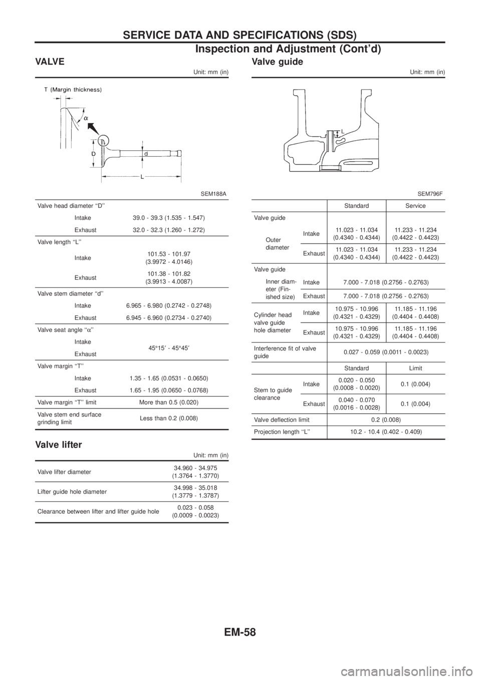
VA LV E
Unit: mm (in)
SEM188A
Valve head diameter ``D''
Intake 39.0 - 39.3 (1.535 - 1.547)
Exhaust 32.0 - 32.3 (1.260 - 1.272)
Valve length ``L''
Intake101.53 - 101.97
(3.9972 - 4.0146)
Exhaust101.38 - 101.82
(3.9913 - 4.0087)
Valve stem diameter ``d''
Intake 6.965 - 6.980 (0.2742 - 0.2748)
Exhaust 6.945 - 6.960 (0.2734 - 0.2740)
Valve seat angle ``a''
Intake
45É15¢- 45É45¢
Exhaust
Valve margin ``T''
Intake 1.35 - 1.65 (0.0531 - 0.0650)
Exhaust 1.65 - 1.95 (0.0650 - 0.0768)
Valve margin ``T'' limit More than 0.5 (0.020)
Valve stem end surface
grinding limitLess than 0.2 (0.008)
Valve lifter
Unit: mm (in)
Valve lifter diameter34.960 - 34.975
(1.3764 - 1.3770)
Lifter guide hole diameter34.998 - 35.018
(1.3779 - 1.3787)
Clearance between lifter and lifter guide hole0.023 - 0.058
(0.0009 - 0.0023)
Valve guide
Unit: mm (in)
SEM796F
Standard Service
Valve guide
Outer
diameterIntake11.023 - 11.034
(0.4340 - 0.4344)11.233 - 11.234
(0.4422 - 0.4423)
Exhaust11.023 - 11.034
(0.4340 - 0.4344)11.233 - 11.234
(0.4422 - 0.4423)
Valve guide
Inner diam-
eter (Fin-
ished size)Intake 7.000 - 7.018 (0.2756 - 0.2763)
Exhaust 7.000 - 7.018 (0.2756 - 0.2763)
Cylinder head
valve guide
hole diameterIntake10.975 - 10.996
(0.4321 - 0.4329)11.185 - 11.196
(0.4404 - 0.4408)
Exhaust10.975 - 10.996
(0.4321 - 0.4329)11.185 - 11.196
(0.4404 - 0.4408)
Interference ®t of valve
guide0.027 - 0.059 (0.0011 - 0.0023)
Standard Limit
Stem to guide
clearanceIntake0.020 - 0.050
(0.0008 - 0.0020)0.1 (0.004)
Exhaust0.040 - 0.070
(0.0016 - 0.0028)0.1 (0.004)
Valve de¯ection limit 0.2 (0.008)
Projection length ``L'' 10.2 - 10.4 (0.402 - 0.409)
SERVICE DATA AND SPECIFICATIONS (SDS)
Inspection and Adjustment (Cont'd)
EM-58
Page 727 of 1226
Valve seat
Unit: mm (in)
SEM788BASEM773BA
SEM790BASEM789BA
Cylinder head to valve distance
Unit: mm (in)
SEM724C
Standard
Intakeþ0.069 to 0.269
(þ0.0027 to 0.0106)
Exhaustþ0.069 to 0.269
(þ0.0027 to 0.0106)
Valve spring
Free height mm (in)
Outer 42.25 (1.6634)
Inner 36.57 (1.4398)
Pressure height/Load
mm/N (mm/kg, in/lb)
Outer25.7/437.69 (25.7/44.63,
1.012/98.41)
Inner22.2/233.21 (22.2/23.78,
0.874/52.43)
Out-of-square mm (in)
Outer 1.9 (0.075)
Inner 1.6 (0.063)
SERVICE DATA AND SPECIFICATIONS (SDS)
Inspection and Adjustment (Cont'd)
EM-59
Page 728 of 1226

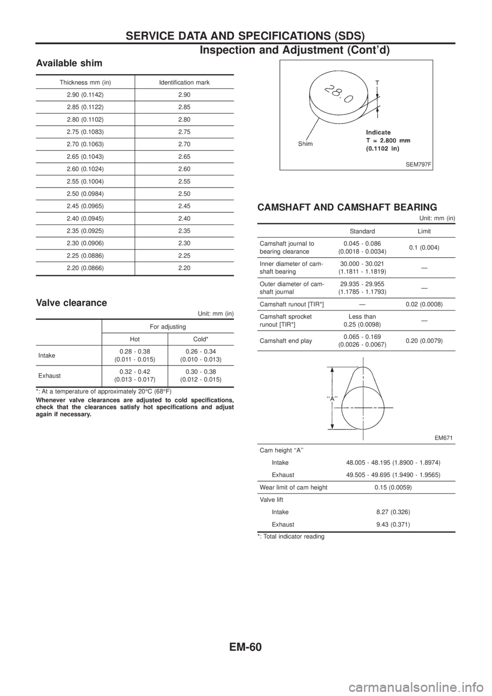
Available shim
Thickness mm (in) Identi®cation mark
2.90 (0.1142) 2.90
2.85 (0.1122) 2.85
2.80 (0.1102) 2.80
2.75 (0.1083) 2.75
2.70 (0.1063) 2.70
2.65 (0.1043) 2.65
2.60 (0.1024) 2.60
2.55 (0.1004) 2.55
2.50 (0.0984) 2.50
2.45 (0.0965) 2.45
2.40 (0.0945) 2.40
2.35 (0.0925) 2.35
2.30 (0.0906) 2.30
2.25 (0.0886) 2.25
2.20 (0.0866) 2.20
Valve clearance
Unit: mm (in)
For adjusting
Hot Cold*
Intake0.28 - 0.38
(0.011 - 0.015)0.26 - 0.34
(0.010 - 0.013)
Exhaust0.32 - 0.42
(0.013 - 0.017)0.30 - 0.38
(0.012 - 0.015)
*: At a temperature of approximately 20ÉC (68ÉF)
Whenever valve clearances are adjusted to cold speci®cations,
check that the clearances satisfy hot speci®cations and adjust
again if necessary.
CAMSHAFT AND CAMSHAFT BEARING
Unit: mm (in)
Standard Limit
Camshaft journal to
bearing clearance0.045 - 0.086
(0.0018 - 0.0034)0.1 (0.004)
Inner diameter of cam-
shaft bearing30.000 - 30.021
(1.1811 - 1.1819)Ð
Outer diameter of cam-
shaft journal29.935 - 29.955
(1.1785 - 1.1793)Ð
Camshaft runout [TIR*] Ð 0.02 (0.0008)
Camshaft sprocket
runout [TIR*]Less than
0.25 (0.0098)Ð
Camshaft end play0.065 - 0.169
(0.0026 - 0.0067)0.20 (0.0079)
EM671
Cam height ``A''
Intake 48.005 - 48.195 (1.8900 - 1.8974)
Exhaust 49.505 - 49.695 (1.9490 - 1.9565)
Wear limit of cam height 0.15 (0.0059)
Valve lift
Intake 8.27 (0.326)
Exhaust 9.43 (0.371)
*: Total indicator reading
SEM797F
SERVICE DATA AND SPECIFICATIONS (SDS)
Inspection and Adjustment (Cont'd)
EM-60
Page 762 of 1226
ACCELERATOR CONTROL, FUEL &
EXHAUST SYSTEMS
SECTION
FE
CONTENTS
ACCELERATOR CONTROL SYSTEM...........................1
Accelerator Control System .........................................1FUEL SYSTEM................................................................2
EXHAUST SYSTEM........................................................3
FE
Page 765 of 1226
CAUTION:
+Always replace exhaust gaskets with new ones when reas-
sembling. If gasket is left on ¯ange surface, scrape off
completely as shown at left.
+With engine running, check all tube connections for
exhaust gas leaks, and entire system for unusual noises.
+Ensure that mounting brackets and mounting insulators
are installed properly and free from undue stress. Improper
installation could result in excessive noise or vibration.
SFE180A
SFE516A
EXHAUST SYSTEM
FE-3
Page 775 of 1226

General Precautions
+Do not operate the engine for an extended period of time with-
out proper exhaust ventilation.
Keep the work area well ventilated and free of any in¯ammable
materials. Special care should be taken when handling any
in¯ammable or poisonous materials, such as gasoline, refriger-
ant gas, etc. When working in a pit or other enclosed area, be
sure to properly ventilate the area before working with hazard-
ous materials.
Do not smoke while working on the vehicle.
+Before jacking up the vehicle, apply wheel chocks or other tire
blocks to the wheels to prevent the vehicle from moving. After
jacking up the vehicle, support the vehicle weight with safety
stands at the points designated for proper lifting before work-
ing on the vehicle.
These operations should be done on a level surface.
+When removing a heavy component such as the engine or
transaxle/transmission, be careful not to lose your balance and
drop it. Also, do not allow it to strike adjacent parts, especially
the brake tubes and master cylinder.
+Before starting repairs which do not require battery power:
Turn off ignition switch.
Disconnect the negative battery terminal.
+To prevent serious burns:
Avoid contact with hot metal parts.
Do not remove the radiator cap when the engine is hot.
+Before servicing the vehicle:
Protect fenders, upholstery and carpeting with appropriate cov-
ers.
Take caution that keys, buckles or buttons do not scratch paint.
SGI285
SGI231
SEF289H
SGI233
SGI234
PRECAUTIONS
GI-2