Page 698 of 1226
CAUTION:
+When installing sliding parts such as camshaft and oil
seal, be sure to apply new engine oil on their sliding sur-
faces.
+When tightening cylinder head bolts, apply new engine oil
to thread portions and seat surfaces of bolts.
Removal
1. Remove charge air cooler assembly.
2. Set No. 1 cylinder at BDC on its expansion stroke.
3. Drain engine coolant from drain plugs on cylinder block and
radiator.
4. Remove air cleaner and/or air duct.
5. Remove timing belt.
6. Remove rocker cover securing bolts/nuts in numerical order
shown in ®gure.
To install rocker cover, tighten bolts/nuts in reverse order of
removal. Tighten in two or three stages.
7. Remove camshaft sprocket, injection pump drive sprocket and
back cover.
8. Disconnect exhaust manifold from exhaust tube.
9. Remove intake and exhaust manifold.
To install manifolds, tighten bolts/nuts in reverse order of
removal. Tighten in two or three stages.
SEM786F
SEM711B
SEM431C
CYLINDER HEAD
EM-30
Page 702 of 1226
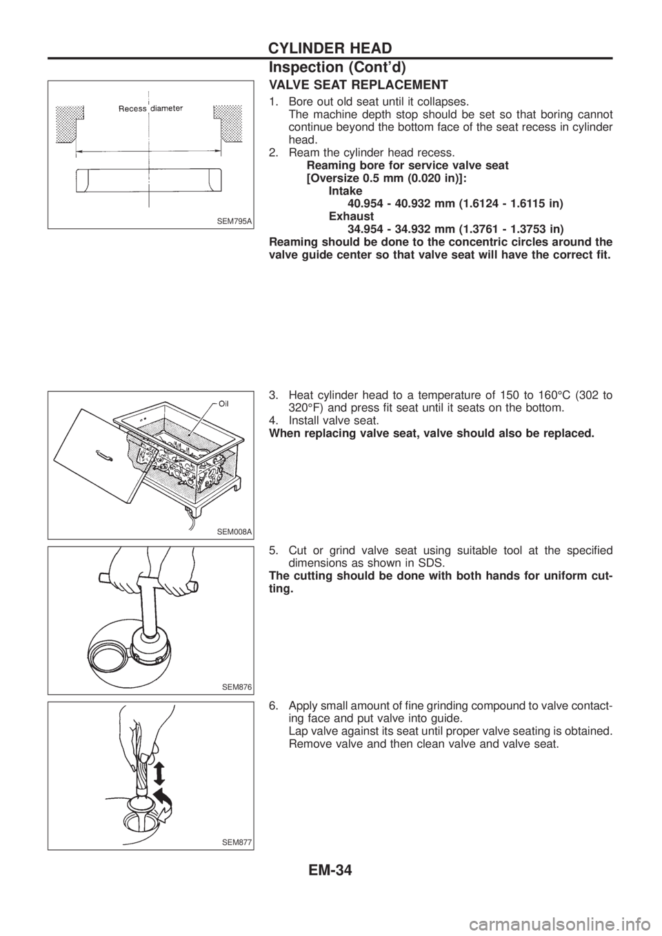
VALVE SEAT REPLACEMENT
1. Bore out old seat until it collapses.
The machine depth stop should be set so that boring cannot
continue beyond the bottom face of the seat recess in cylinder
head.
2. Ream the cylinder head recess.
Reaming bore for service valve seat
[Oversize 0.5 mm (0.020 in)]:
Intake
40.954 - 40.932 mm (1.6124 - 1.6115 in)
Exhaust
34.954 - 34.932 mm (1.3761 - 1.3753 in)
Reaming should be done to the concentric circles around the
valve guide center so that valve seat will have the correct ®t.
3. Heat cylinder head to a temperature of 150 to 160ÉC (302 to
320ÉF) and press ®t seat until it seats on the bottom.
4. Install valve seat.
When replacing valve seat, valve should also be replaced.
5. Cut or grind valve seat using suitable tool at the speci®ed
dimensions as shown in SDS.
The cutting should be done with both hands for uniform cut-
ting.
6. Apply small amount of ®ne grinding compound to valve contact-
ing face and put valve into guide.
Lap valve against its seat until proper valve seating is obtained.
Remove valve and then clean valve and valve seat.
SEM795A
SEM008A
SEM876
SEM877
CYLINDER HEAD
Inspection (Cont'd)
EM-34
Page 703 of 1226
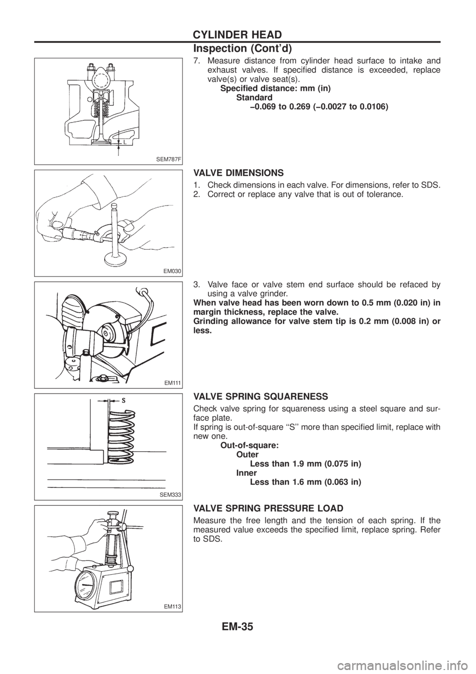
7. Measure distance from cylinder head surface to intake and
exhaust valves. If speci®ed distance is exceeded, replace
valve(s) or valve seat(s).
Speci®ed distance: mm (in)
Standard
þ0.069 to 0.269 (þ0.0027 to 0.0106)
VALVE DIMENSIONS
1. Check dimensions in each valve. For dimensions, refer to SDS.
2. Correct or replace any valve that is out of tolerance.
3. Valve face or valve stem end surface should be refaced by
using a valve grinder.
When valve head has been worn down to 0.5 mm (0.020 in) in
margin thickness, replace the valve.
Grinding allowance for valve stem tip is 0.2 mm (0.008 in) or
less.
VALVE SPRING SQUARENESS
Check valve spring for squareness using a steel square and sur-
face plate.
If spring is out-of-square ``S'' more than speci®ed limit, replace with
new one.
Out-of-square:
Outer
Less than 1.9 mm (0.075 in)
Inner
Less than 1.6 mm (0.063 in)
VALVE SPRING PRESSURE LOAD
Measure the free length and the tension of each spring. If the
measured value exceeds the speci®ed limit, replace spring. Refer
to SDS.
SEM787F
EM030
E M 111
SEM333
EM113
CYLINDER HEAD
Inspection (Cont'd)
EM-35
Page 705 of 1226
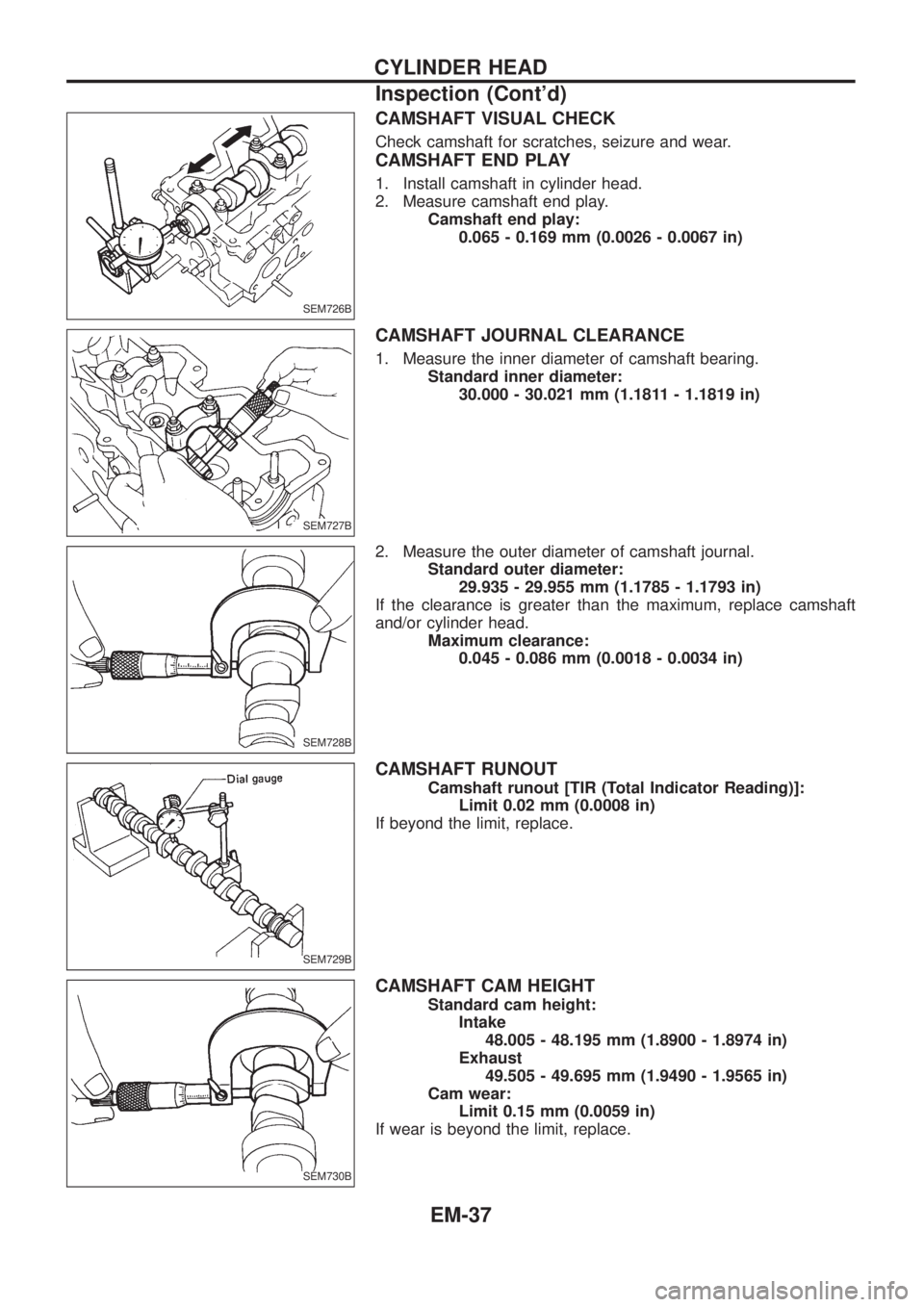
CAMSHAFT VISUAL CHECK
Check camshaft for scratches, seizure and wear.
CAMSHAFT END PLAY
1. Install camshaft in cylinder head.
2. Measure camshaft end play.
Camshaft end play:
0.065 - 0.169 mm (0.0026 - 0.0067 in)
CAMSHAFT JOURNAL CLEARANCE
1. Measure the inner diameter of camshaft bearing.
Standard inner diameter:
30.000 - 30.021 mm (1.1811 - 1.1819 in)
2. Measure the outer diameter of camshaft journal.
Standard outer diameter:
29.935 - 29.955 mm (1.1785 - 1.1793 in)
If the clearance is greater than the maximum, replace camshaft
and/or cylinder head.
Maximum clearance:
0.045 - 0.086 mm (0.0018 - 0.0034 in)
CAMSHAFT RUNOUT
Camshaft runout [TIR (Total Indicator Reading)]:
Limit 0.02 mm (0.0008 in)
If beyond the limit, replace.
CAMSHAFT CAM HEIGHT
Standard cam height:
Intake
48.005 - 48.195 mm (1.8900 - 1.8974 in)
Exhaust
49.505 - 49.695 mm (1.9490 - 1.9565 in)
Cam wear:
Limit 0.15 mm (0.0059 in)
If wear is beyond the limit, replace.
SEM726B
SEM727B
SEM728B
SEM729B
SEM730B
CYLINDER HEAD
Inspection (Cont'd)
EM-37
Page 706 of 1226
Assembly
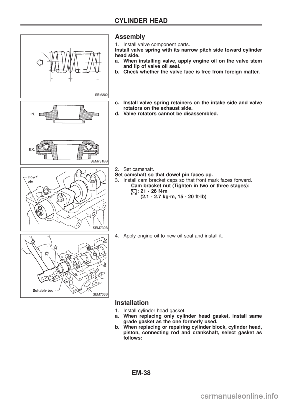
1. Install valve component parts.
Install valve spring with its narrow pitch side toward cylinder
head side.
a. When installing valve, apply engine oil on the valve stem
and lip of valve oil seal.
b. Check whether the valve face is free from foreign matter.
c. Install valve spring retainers on the intake side and valve
rotators on the exhaust side.
d. Valve rotators cannot be disassembled.
2. Set camshaft.
Set camshaft so that dowel pin faces up.
3. Install cam bracket caps so that front mark faces forward.
Cam bracket nut (Tighten in two or three stages):
:21-26Nzm
(2.1 - 2.7 kg-m, 15 - 20 ft-lb)
4. Apply engine oil to new oil seal and install it.
Installation
1. Install cylinder head gasket.
a. When replacing only cylinder head gasket, install same
grade gasket as the one formerly used.
b. When replacing or repairing cylinder block, cylinder head,
piston, connecting rod and crankshaft, select gasket as
follows:
SEM202
SEM731BB
SEM732B
SEM733B
CYLINDER HEAD
EM-38
Page 708 of 1226
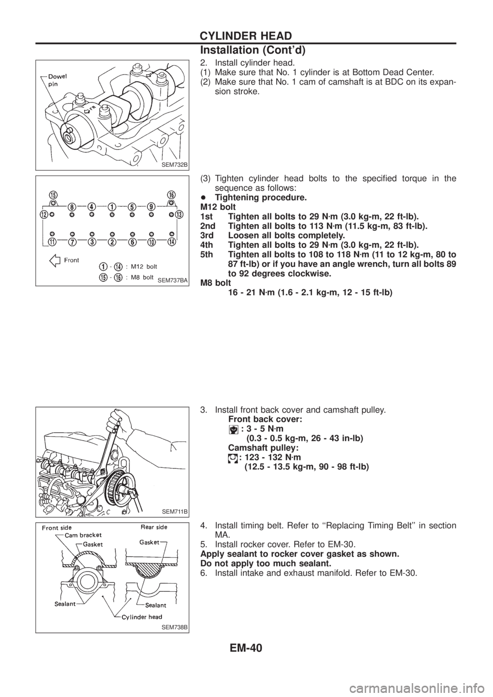
2. Install cylinder head.
(1) Make sure that No. 1 cylinder is at Bottom Dead Center.
(2) Make sure that No. 1 cam of camshaft is at BDC on its expan-
sion stroke.
(3) Tighten cylinder head bolts to the speci®ed torque in the
sequence as follows:
+Tightening procedure.
M12 bolt
1st Tighten all bolts to 29 Nzm (3.0 kg-m, 22 ft-lb).
2nd Tighten all bolts to 113 Nzm (11.5 kg-m, 83 ft-lb).
3rd Loosen all bolts completely.
4th Tighten all bolts to 29 Nzm (3.0 kg-m, 22 ft-lb).
5th Tighten all bolts to 108 to 118 Nzm (11 to 12 kg-m, 80 to
87 ft-lb) or if you have an angle wrench, turn all bolts 89
to 92 degrees clockwise.
M8 bolt
16-21Nzm (1.6 - 2.1 kg-m, 12 - 15 ft-lb)
3. Install front back cover and camshaft pulley.
Front back cover:
:3-5Nzm
(0.3 - 0.5 kg-m, 26 - 43 in-lb)
Camshaft pulley:
: 123 - 132 Nzm
(12.5 - 13.5 kg-m, 90 - 98 ft-lb)
4. Install timing belt. Refer to ``Replacing Timing Belt'' in section
MA.
5. Install rocker cover. Refer to EM-30.
Apply sealant to rocker cover gasket as shown.
Do not apply too much sealant.
6. Install intake and exhaust manifold. Refer to EM-30.
SEM732B
SEM737BA
SEM711B
SEM738B
CYLINDER HEAD
Installation (Cont'd)
EM-40
Page 709 of 1226

Checking
Check valve clearance while engine is warm and not running.
1. Remove rocker cover.
2. Set No. 1 cylinder at TDC on its compression stroke.
+Align pointer with TDC mark on crankshaft pulley.
+Check that valve lifters on No. 1 cylinder are loose and valve
lifters on No. 6 are tight.
If not, turn crankshaft one revolution (360É) and align as
described above.
3. Check only those valves shown in the ®gure.
No. 1 No. 2 No. 3 No. 4 No. 5 No. 6
INT EXH INT EXH INT EXH INT EXH INT EXH INT EXH
No. 1 cylin-
der at TDCjjj jj j
+Using a feeler gauge, measure clearance between valve lifter
and camshaft.
+Record any valve clearance measurements which are out of
speci®cation. They will be used later to determine the required
replacement adjusting shim.
Valve clearance for checking (Hot):
Intake
0.28 - 0.38 mm (0.011 - 0.015 in)
Exhaust
0.32 - 0.42 mm (0.013 - 0.017 in)
4. Turn crankshaft one revolution (360É) and align mark on crank-
shaft pulley with pointer.
5. Check only those valves shown in the ®gure.
No. 1 No. 2 No. 3 No. 4 No. 5 No. 6
INT EXH INT EXH INT EXH INT EXH INT EXH INT EXH
No. 6 cylin-
der at TDCjj jj jj
+Use the same procedure as mentioned in step 4.
6. If all valve clearances are within speci®cation, install the follow-
ing parts:
+Rocker cover
SEM790F
SEM799F
SEM634F
SEM800F
VALVE CLEARANCE
EM-41
Page 710 of 1226
Adjusting
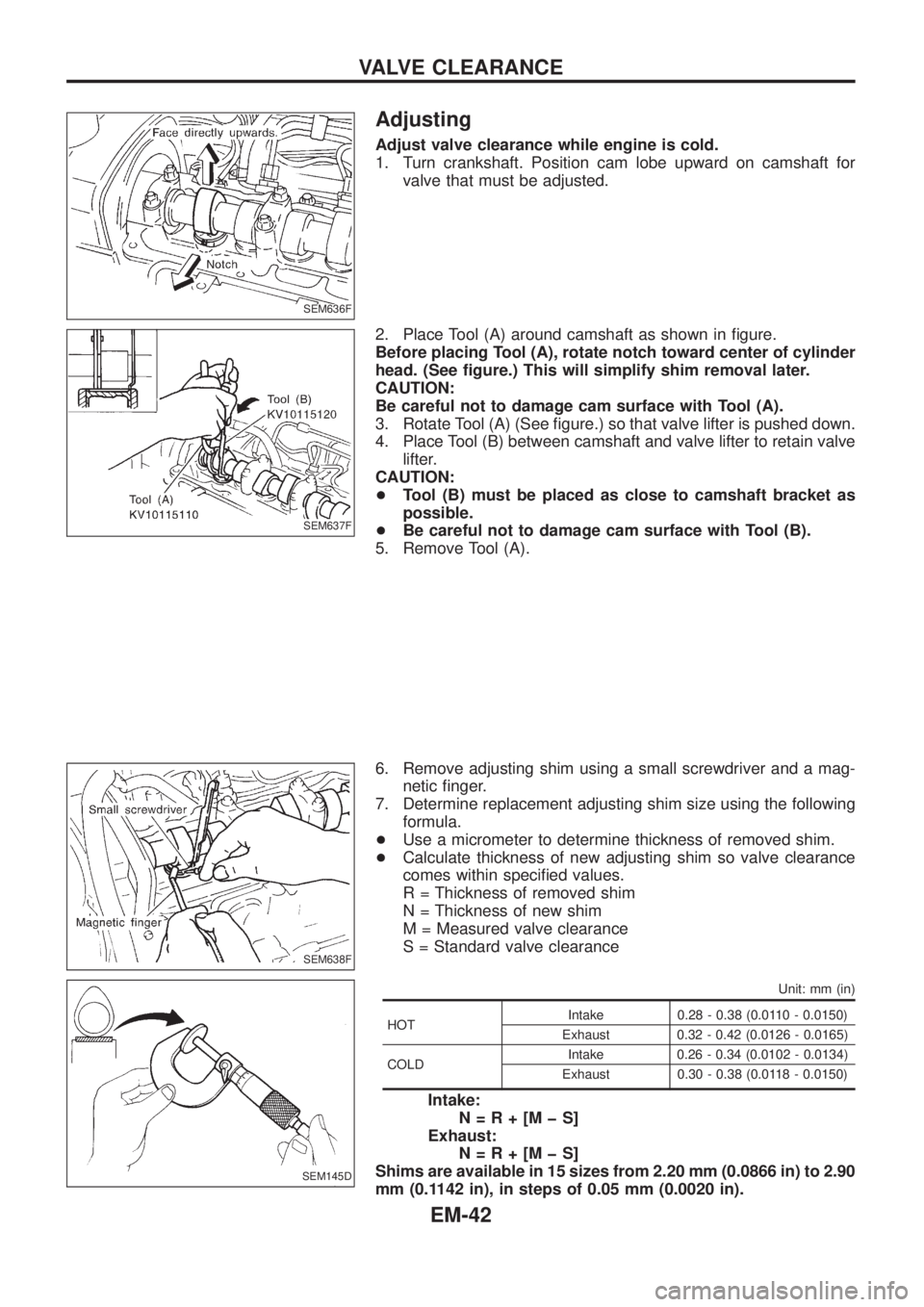
Adjust valve clearance while engine is cold.
1. Turn crankshaft. Position cam lobe upward on camshaft for
valve that must be adjusted.
2. Place Tool (A) around camshaft as shown in ®gure.
Before placing Tool (A), rotate notch toward center of cylinder
head. (See ®gure.) This will simplify shim removal later.
CAUTION:
Be careful not to damage cam surface with Tool (A).
3. Rotate Tool (A) (See ®gure.) so that valve lifter is pushed down.
4. Place Tool (B) between camshaft and valve lifter to retain valve
lifter.
CAUTION:
+Tool (B) must be placed as close to camshaft bracket as
possible.
+Be careful not to damage cam surface with Tool (B).
5. Remove Tool (A).
6. Remove adjusting shim using a small screwdriver and a mag-
netic ®nger.
7. Determine replacement adjusting shim size using the following
formula.
+Use a micrometer to determine thickness of removed shim.
+Calculate thickness of new adjusting shim so valve clearance
comes within speci®ed values.
R = Thickness of removed shim
N = Thickness of new shim
M = Measured valve clearance
S = Standard valve clearance
Unit: mm (in)
HOTIntake 0.28 - 0.38 (0.0110 - 0.0150)
Exhaust 0.32 - 0.42 (0.0126 - 0.0165)
COLDIntake 0.26 - 0.34 (0.0102 - 0.0134)
Exhaust 0.30 - 0.38 (0.0118 - 0.0150)
Intake:
N=R+[MþS]
Exhaust:
N=R+[MþS]
Shims are available in 15 sizes from 2.20 mm (0.0866 in) to 2.90
mm (0.1142 in), in steps of 0.05 mm (0.0020 in).
SEM636F
SEM637F
SEM638F
SEM145D
VALVE CLEARANCE
EM-42