Page 605 of 1226

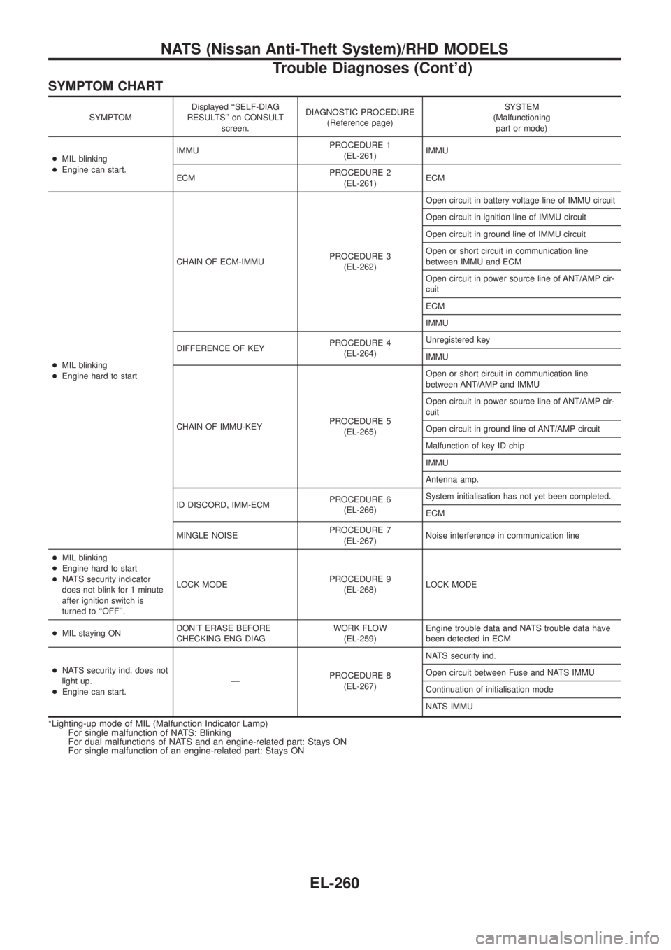
SYMPTOM CHART
SYMPTOMDisplayed ``SELF-DIAG
RESULTS'' on CONSULT
screen.DIAGNOSTIC PROCEDURE
(Reference page)SYSTEM
(Malfunctioning
part or mode)
+MIL blinking
+Engine can start.IMMUPROCEDURE 1
(EL-261)IMMU
ECMPROCEDURE 2
(EL-261)ECM
+MIL blinking
+Engine hard to startCHAIN OF ECM-IMMUPROCEDURE 3
(EL-262)Open circuit in battery voltage line of IMMU circuit
Open circuit in ignition line of IMMU circuit
Open circuit in ground line of IMMU circuit
Open or short circuit in communication line
between IMMU and ECM
Open circuit in power source line of ANT/AMP cir-
cuit
ECM
IMMU
DIFFERENCE OF KEYPROCEDURE 4
(EL-264)Unregistered key
IMMU
CHAIN OF IMMU-KEYPROCEDURE 5
(EL-265)Open or short circuit in communication line
between ANT/AMP and IMMU
Open circuit in power source line of ANT/AMP cir-
cuit
Open circuit in ground line of ANT/AMP circuit
Malfunction of key ID chip
IMMU
Antenna amp.
ID DISCORD, IMM-ECMPROCEDURE 6
(EL-266)System initialisation has not yet been completed.
ECM
MINGLE NOISEPROCEDURE 7
(EL-267)Noise interference in communication line
+MIL blinking
+Engine hard to start
+NATS security indicator
does not blink for 1 minute
after ignition switch is
turned to ``OFF''.LOCK MODEPROCEDURE 9
(EL-268)LOCK MODE
+MIL staying ONDON'T ERASE BEFORE
CHECKING ENG DIAGWORK FLOW
(EL-259)Engine trouble data and NATS trouble data have
been detected in ECM
+NATS security ind. does not
light up.
+Engine can start.ÐPROCEDURE 8
(EL-267)NATS security ind.
Open circuit between Fuse and NATS IMMU
Continuation of initialisation mode
NATS IMMU
*Lighting-up mode of MIL (Malfunction Indicator Lamp)
For single malfunction of NATS: Blinking
For dual malfunctions of NATS and an engine-related part: Stays ON
For single malfunction of an engine-related part: Stays ON
NATS (Nissan Anti-Theft System)/RHD MODELS
Trouble Diagnoses (Cont'd)
EL-260
Page 610 of 1226

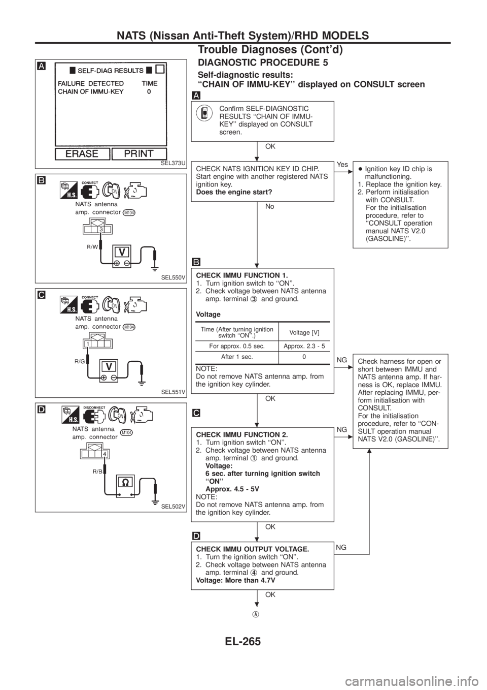
DIAGNOSTIC PROCEDURE 5
Self-diagnostic results:
``CHAIN OF IMMU-KEY'' displayed on CONSULT screen
Con®rm SELF-DIAGNOSTIC
RESULTS ``CHAIN OF IMMU-
KEY'' displayed on CONSULT
screen.
OK
CHECK NATS IGNITION KEY ID CHIP.
Start engine with another registered NATS
ignition key.
Does the engine start?
No
cYe s
+Ignition key ID chip is
malfunctioning.
1. Replace the ignition key.
2. Perform initialisation
with CONSULT.
For the initialisation
procedure, refer to
``CONSULT operation
manual NATS V2.0
(GASOLINE)''.
CHECK IMMU FUNCTION 1.
1. Turn ignition switch to ``ON''.
2. Check voltage between NATS antenna
amp. terminalj
3and ground.
Voltage
NOTE:
Do not remove NATS antenna amp. from
the ignition key cylinder.
OK
cNG
Check harness for open or
short between IMMU and
NATS antenna amp. If har-
ness is OK, replace IMMU.
After replacing IMMU, per-
form initialisation with
CONSULT.
For the initialisation
procedure, refer to ``CON-
SULT operation manual
NATS V2.0 (GASOLINE)''.
CHECK IMMU FUNCTION 2.
1. Turn ignition switch ``ON''.
2. Check voltage between NATS antenna
amp. terminalj
1and ground.
Voltage:
6 sec. after turning ignition switch
``ON''
Approx. 4.5 - 5V
NOTE:
Do not remove NATS antenna amp. from
the ignition key cylinder.
OK
cNG
CHECK IMMU OUTPUT VOLTAGE.
1. Turn the ignition switch ``ON''.
2. Check voltage between NATS antenna
amp. terminalj
4and ground.
Voltage: More than 4.7V
OK
m
NG
j
A
Time (After turning ignition
switch ``ON''.)Voltage [V]
For approx. 0.5 sec. Approx. 2.3 - 5
After 1 sec. 0
SEL373U
SEL550V
SEL551V
SEL502V
.
.
.
.
.
NATS (Nissan Anti-Theft System)/RHD MODELS
Trouble Diagnoses (Cont'd)
EL-265
Page 612 of 1226

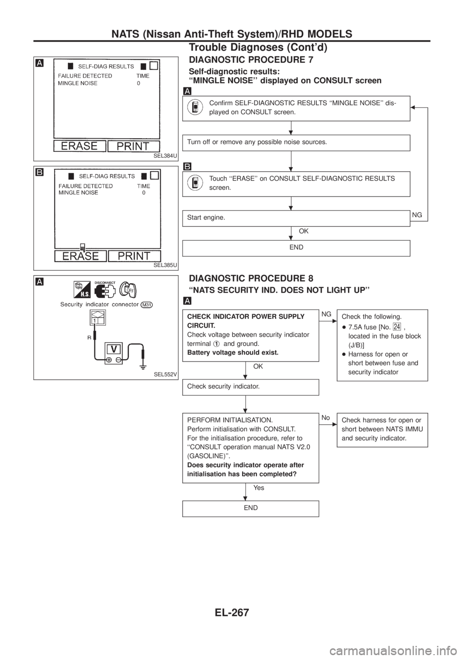
DIAGNOSTIC PROCEDURE 7
Self-diagnostic results:
``MINGLE NOISE'' displayed on CONSULT screen
Con®rm SELF-DIAGNOSTIC RESULTS ``MINGLE NOISE'' dis-
played on CONSULT screen.b
Turn off or remove any possible noise sources.
Touch ``ERASE'' on CONSULT SELF-DIAGNOSTIC RESULTS
screen.
Start engine.
OKNG
END
DIAGNOSTIC PROCEDURE 8
``NATS SECURITY IND. DOES NOT LIGHT UP''
CHECK INDICATOR POWER SUPPLY
CIRCUIT.
Check voltage between security indicator
terminalj
1and ground.
Battery voltage should exist.
OK
cNG
Check the following.
+7.5A fuse [No.
24,
located in the fuse block
(J/B)]
+Harness for open or
short between fuse and
security indicator
Check security indicator.
PERFORM INITIALISATION.
Perform initialisation with CONSULT.
For the initialisation procedure, refer to
``CONSULT operation manual NATS V2.0
(GASOLINE)''.
Does security indicator operate after
initialisation has been completed?
Ye s
cNo
Check harness for open or
short between NATS IMMU
and security indicator.
END
SEL384U
SEL385U
SEL552V
.
.
.
.
.
.
.
NATS (Nissan Anti-Theft System)/RHD MODELS
Trouble Diagnoses (Cont'd)
EL-267
Page 613 of 1226

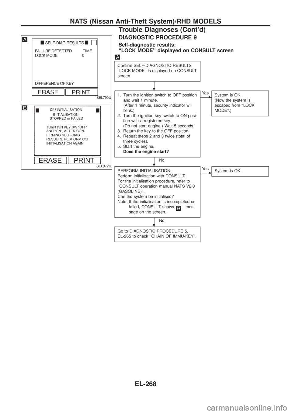
DIAGNOSTIC PROCEDURE 9
Self-diagnostic results:
``LOCK MODE'' displayed on CONSULT screen
Con®rm SELF-DIAGNOSTIC RESULTS
``LOCK MODE'' is displayed on CONSULT
screen.
1. Turn the ignition switch to OFF position
and wait 1 minute.
(After 1 minute, security indicator will
blink.)
2. Turn the ignition key switch to ON posi-
tion with a registered key.
(Do not start engine.) Wait 5 seconds.
3. Return the key to the OFF position.
4. Repeat steps 2 and 3 twice (total of
three cycles).
5. Start the engine.
Does the engine start?
No
cYe s
System is OK.
(Now the system is
escaped from ``LOCK
MODE''.)
PERFORM INITIALISATION.
Perform initialisation with CONSULT.
For the initialisation procedure, refer to
``CONSULT operation manual NATS V2.0
(GASOLINE)''.
Can the system be initialised?
Note: If the initialisation is incompleted or
failed, CONSULT shows
mes-
sage on the screen.
No
cYe s
System is OK.
Go to DIAGNOSTIC PROCEDURE 5,
EL-265 to check ``CHAIN OF IMMU-KEY''.
SEL790U
SEL372U
.
.
.
NATS (Nissan Anti-Theft System)/RHD MODELS
Trouble Diagnoses (Cont'd)
EL-268
Page 614 of 1226
Engine Compartment
CEL750
LOCATION OF ELECTRICAL UNITS
EL-269
Page 620 of 1226
How to Read Harness Layout
Example:
G2E1B/6: ASCD ACTUATOR
Connector color / Cavity
Connector number
Grid reference
The following Harness Layouts use a map style grid to help locate connectors on the drawings:
+Main Harness
+Engine Room Harness (Engine Compartment)
To use the grid reference
1) Find the desired connector number on the connector list.
2) Find the grid reference.
3) On the drawing, ®nd the crossing of the grid reference letter column and number row.
4) Find the connector number in the crossing zone.
5) Follow the line (if used) to the connector.
CONNECTOR SYMBOL
Main symbols of connector (in Harness Layout) are indicated in the below.
Connector typeWater proof type Standard type
Male Female Male Female
+Cavity: Less than 4
+Relay connector
+Cavity: From 5 to 8
+Cavity: More than 9
ÐÐ
+Ground terminal etc.
Ð
HARNESS LAYOUT
EL-275
Page 631 of 1226
Engine Room Harness/LHD Models
CEL822
HARNESS LAYOUT
EL-286
Page 632 of 1226
CEL823
HARNESS LAYOUT
Engine Room Harness/LHD Models (Cont'd)
EL-287