Page 680 of 1226

6. Fit compression gauge adapter to cylinder head.
7. Crank engine and read gauge indication.
Crank speed: 200 rpm
Compression pressure:
Standard
3,040 kPa (30.4 bar, 31 kg/cm
2, 441 psi)
Limit
2,452 kPa (24.5 bar, 25 kg/cm
2, 356 psi)
Differential limit between cylinders
490 kPa (4.9 bar, 5 kg/cm
2, 71 psi)
8. If the pressure appears low, pour about 3 m!(0.11 Imp ¯ oz)
of engine oil through nozzle holes and repeat test.
For indications of test, refer to the following table.
Gauge indication during tests Trouble diagnosis
SEM857
+Piston rings are worn or
damaged.
SEM858
+If two adjacent cylinders
are low, gasket is dam-
aged.
+Valve is sticking.
+Valve seat or valve con-
tact surface is incorrected.
9. Replace nozzle gaskets and install injection nozzles.
New nozzle gasket installation direction is as shown.
Nozzle to cylinder head:
:59-69Nzm
(6.0 - 7.0 kg-m, 43 - 51 ft-lb)
SEM706B
SEM708B
COMPRESSION PRESSURE
Measurement of Compression Pressure
(Cont'd)
EM-12
First readingSecond
reading
Increased
reading
Same reading
maintained
Page 682 of 1226
Removal
1. Remove oil pan guard.
2. Drain engine oil.
+When installing drain plug washer, ensure it faces in correct
direction.
+Discard oil drain plug washer and install a new one.
Drain plug:
:29-39Nzm (3.0 - 4.0 kg-m, 22 - 29 ft-lb)
SEM782F
SEM783F
SEM063B
OIL PAN
EM-14
Page 683 of 1226
3. Remove engine gussets and oil pan bolts.
+Remove bolts/nuts in numerical order shown in ®gure, alternat-
ing left and right ones toward the center.
4. Remove oil pump assembly.
Installation
Always install with new oil seal.
1. Install oil pump assembly.
Location Bolt length mm (in)
V120 (0.79)
V235 (1.38)
V345 (1.77)
V455 (2.17)
2. Install oil pan. Tighten bolts in the order shown in the ®gure.
+Always replace oil pan gaskets with new ones when reas-
sembling.
+Install oil pan gasket after cleaning the contacting surface.
+Oil pan bolts/nuts:
Bolt
:8-12Nzm (0.8 - 1.2 kg-m, 69 - 104 in-lb)
Nut
:10-14Nzm (1.0 - 1.4 kg-m, 87 - 122 in-lb)
3. Install engine gusset and oil pan guard.
SEM739B
SEM432C
SEM794F
SEM739BA
OIL PAN
Removal (Cont'd)
EM-15
Page 684 of 1226
CAUTION:
+Do not bend or twist timing belt.
+After removing timing belt, do not turn crankshaft and
camshaft separately because valves will strike piston
heads.
+Make sure that timing belt, camshaft sprocket, crankshaft
sprocket, idler pulley, injection pump pulley and belt ten-
sioner are clean and free from oil and water.
+Align white lines on timing belt with punch mark on cam-
shaft sprocket, crankshaft sprocket and injection pump
pulley.
+Installation should be carried out when engine is cold.
Removal
1. Remove radiator shroud.
2. Remove the following belts.
+Power steering drive belt
+A/C compressor drive belt
+Alternator drive belt
3. Remove cooling fan coupling and water pump pulley.
SMA767BA
TIMING BELT
EM-16
Page 686 of 1226

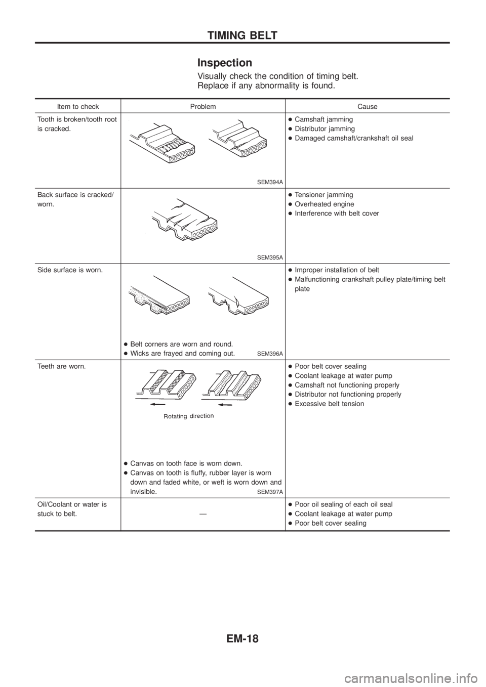
Inspection
Visually check the condition of timing belt.
Replace if any abnormality is found.
Item to check Problem Cause
Tooth is broken/tooth root
is cracked.
SEM394A
+Camshaft jamming
+Distributor jamming
+Damaged camshaft/crankshaft oil seal
Back surface is cracked/
worn.
SEM395A
+Tensioner jamming
+Overheated engine
+Interference with belt cover
Side surface is worn.
+Belt corners are worn and round.
+Wicks are frayed and coming out.
SEM396A
+Improper installation of belt
+Malfunctioning crankshaft pulley plate/timing belt
plate
Teeth are worn.
+Canvas on tooth face is worn down.
+Canvas on tooth is ¯uffy, rubber layer is worn
down and faded white, or weft is worn down and
invisible.
SEM397A
+Poor belt cover sealing
+Coolant leakage at water pump
+Camshaft not functioning properly
+Distributor not functioning properly
+Excessive belt tension
Oil/Coolant or water is
stuck to belt. Ð+Poor oil sealing of each oil seal
+Coolant leakage at water pump
+Poor belt cover sealing
TIMING BELT
EM-18
Page 690 of 1226
CAMSHAFT AND CRANKSHAFT OIL SEAL INSTALLING
DIRECTION AND MANNER
+When installing camshaft and crankshaft oil seals, be care-
ful to install them correctly, as shown in the ®gure.
+Apply engine oil to oil seal lip, outer face, camshaft and
bracket.
+Wipe off excess oil after installing oil seal.
CAMSHAFT OIL SEALS
1. Remove timing belts, sprockets and back covers.
2. Pull out oil seal with a suitable tool.
3. Install new oil seals with a suitable tool.
CRANKSHAFT FRONT OIL SEAL
1. Remove valve timing belt and crankshaft sprocket.
2. Remove oil pan and oil pan gasket.
3. Remove oil pump assembly.
4. Remove front oil seal with a suitable tool.
5. Apply engine oil to new oil seal and install oil seal using a suit-
able tool.
SEM715A
SEM743B
SEM733B
SEM893A
SEM894A
OIL SEAL REPLACEMENT
EM-22
Page 691 of 1226
CRANKSHAFT REAR OIL SEAL
1. Remove transmission assembly. (Refer to ``REMOVAL AND
INSTALLATION'' in MT section.)
2. Remove clutch cover assembly.
3. Remove ¯ywheel and rear plate.
4. Remove oil pan and oil pan gasket.
5. Remove oil seal retainer assembly.
6. Remove traces of liquid gasket using a scraper.
7. Remove rear oil seal from retainer.
8. Apply engine oil to new oil seal and install oil seal using a suit-
able tool.
9. Apply a continuous bead of liquid gasket to rear oil seal
retainer.
a. Coat of liquid gasket should be maintained within 2.0 to 3.0
mm (0.079 to 0.118 in) dia. range.
b. Attach oil seal retainer to cylinder block within ®ve min-
utes after coating.
c. Wait at least 30 minutes before re®lling engine oil or start-
ing engine.
d. Use Genuine Liquid Gasket or equivalent.
SEM896A
SEM895A
SEM897A
SLC822
SEM144B
OIL SEAL REPLACEMENT
EM-23
Page 692 of 1226
Removal and Installation
1. Drain engine coolant.
2. Remove the following:
+Air duct and hoses
+Air intake pipe
+EGR pipe
+Heat shield plates
+Intake manifold
+Front (exhaust) tube
+Oil tube and water tube
3. Remove exhaust manifold with turbocharger from cylinder
head.
4. When installing turbocharger to exhaust manifold, securely
tighten nuts and lock the nuts.
+Turbocharger should not be disassembled.
SEM784F
TURBOCHARGER
EM-24