Page 1062 of 1226
CAUTION:
Do not run engine when one wheel (rear) is off the ground.
Preparation for Disassembly
CHECKING DIFFERENTIAL TORQUE
Measure differential torque with Tool.
If it is not within the speci®cations, inspect components of limited
slip differential.
Differential torque:
108 - 137 Nzm (11 - 14 kg-m, 80 - 101 ft-lb)
Tool number: KV38106400
SPD439A
SPD508
LIMITED SLIP DIFFERENTIAL
PD-20
Page 1093 of 1226

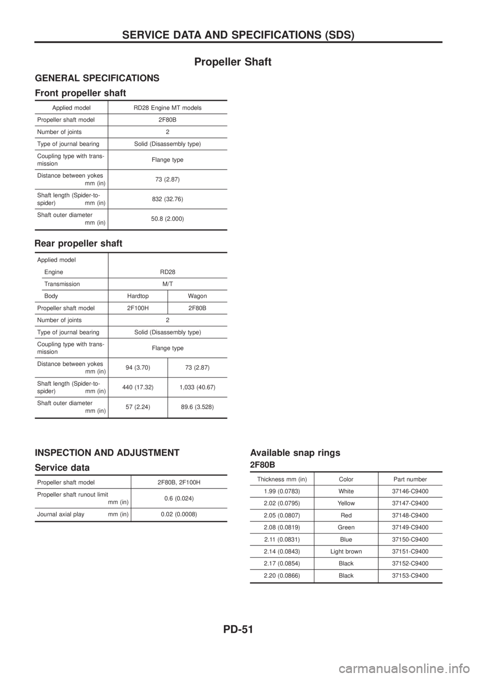
Propeller Shaft
GENERAL SPECIFICATIONS
Front propeller shaft
Applied model RD28 Engine MT models
Propeller shaft model 2F80B
Number of joints 2
Type of journal bearing Solid (Disassembly type)
Coupling type with trans-
missionFlange type
Distance between yokes
mm (in)73 (2.87)
Shaft length (Spider-to-
spider) mm (in)832 (32.76)
Shaft outer diameter
mm (in)50.8 (2.000)
Rear propeller shaft
Applied model
Engine RD28
Transmission M/T
Body Hardtop Wagon
Propeller shaft model 2F100H 2F80B
Number of joints 2
Type of journal bearing Solid (Disassembly type)
Coupling type with trans-
missionFlange type
Distance between yokes
mm (in)94 (3.70) 73 (2.87)
Shaft length (Spider-to-
spider) mm (in)440 (17.32) 1,033 (40.67)
Shaft outer diameter
mm (in)57 (2.24) 89.6 (3.528)
INSPECTION AND ADJUSTMENT
Service data
Propeller shaft model 2F80B, 2F100H
Propeller shaft runout limit
mm (in)0.6 (0.024)
Journal axial play mm (in) 0.02 (0.0008)
Available snap rings
2F80B
Thickness mm (in) Color Part number
1.99 (0.0783) White 37146-C9400
2.02 (0.0795) Yellow 37147-C9400
2.05 (0.0807) Red 37148-C9400
2.08 (0.0819) Green 37149-C9400
2.11 (0.0831) Blue 37150-C9400
2.14 (0.0843) Light brown 37151-C9400
2.17 (0.0854) Black 37152-C9400
2.20 (0.0866) Black 37153-C9400
SERVICE DATA AND SPECIFICATIONS (SDS)
PD-51
Page 1094 of 1226

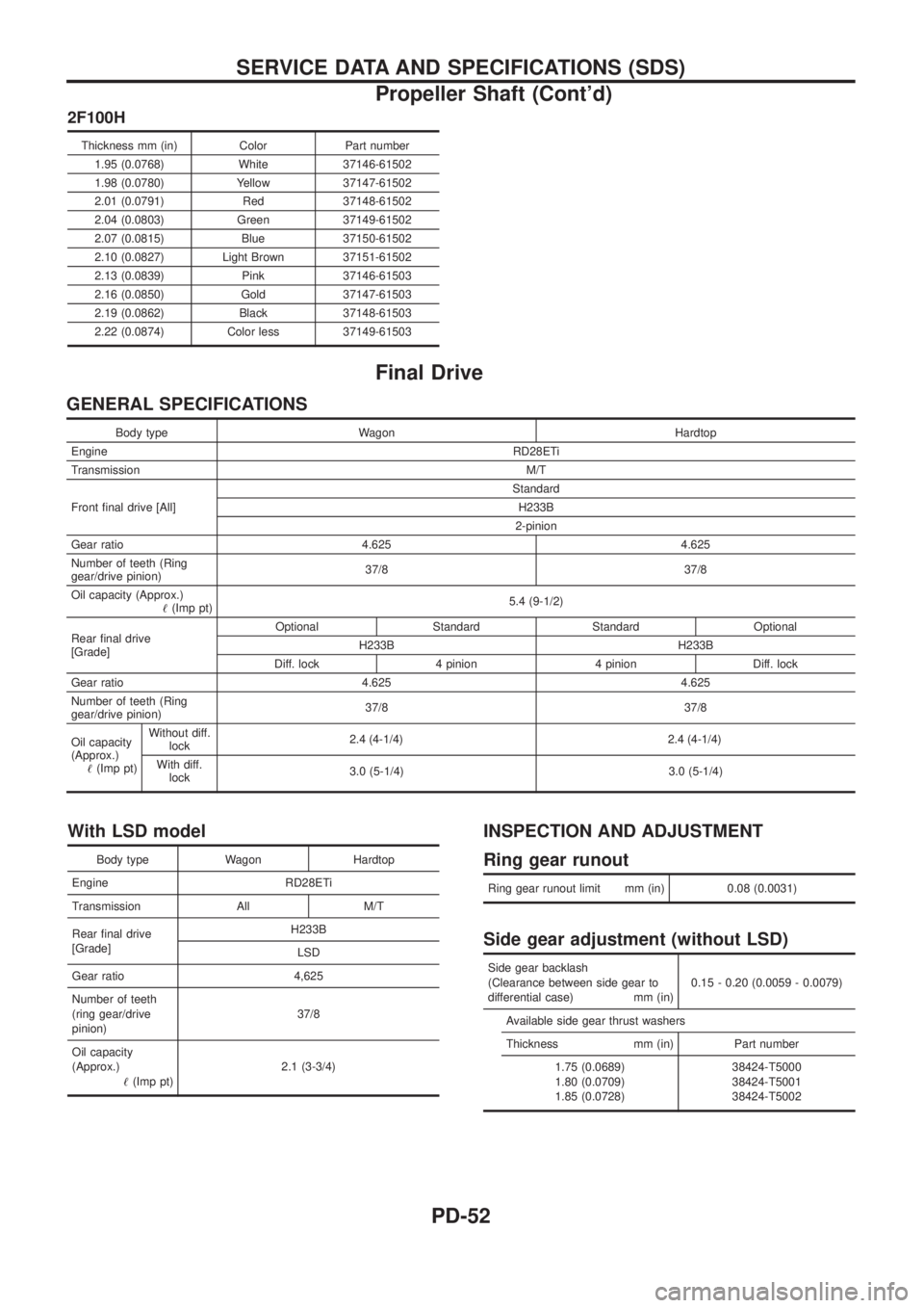
2F100H
Thickness mm (in) Color Part number1.95 (0.0768) White 37146-61502
1.98 (0.0780) Yellow 37147-61502
2.01 (0.0791) Red 37148-61502
2.04 (0.0803) Green 37149-61502
2.07 (0.0815) Blue 37150-61502
2.10 (0.0827) Light Brown 37151-61502
2.13 (0.0839) Pink 37146-61503
2.16 (0.0850) Gold 37147-61503
2.19 (0.0862) Black 37148-61503
2.22 (0.0874) Color less 37149-61503
Final Drive
GENERAL SPECIFICATIONS
Body type Wagon Hardtop
Engine RD28ETi
Transmission M/T
Front ®nal drive [All] Standard
H233B
2-pinion
Gear ratio 4.625 4.625
Number of teeth (Ring
gear/drive pinion) 37/8 37/8
Oil capacity (Approx.) !(Imp pt) 5.4 (9-1/2)
Rear ®nal drive
[Grade] Optional Standard Standard Optional
H233B H233B
Diff. lock 4 pinion 4 pinion Diff. lock
Gear ratio 4.625 4.625
Number of teeth (Ring
gear/drive pinion) 37/8 37/8
Oil capacity
(Approx.) !(Imp pt) Without diff.
lock 2.4 (4
-1/4)2.4 (4-1/4)
With diff.lock 3.0 (5-1/4) 3.0 (5-1/4)
With LSD model
Body type Wagon Hardtop
Engine RD28ETi
Transmission All M/T
Rear ®nal drive
[Grade] H233B
LSD
Gear ratio 4,625
Number of teeth
(ring gear/drive
pinion) 37/8
Oil capacity
(Approx.) !(Imp pt) 2.1 (3-3/4)
INSPECTION AND ADJUSTMENT
Ring gear runout
Ring gear runout limit mm (in) 0.08 (0.0031)
Side gear adjustment (without LSD)
Side gear backlash
(Clearance between side gear to
differential case) mm (in) 0.15 - 0.20 (0.0059 - 0.0079)
Available side gear thrust washers
Thickness mm (in) Part number 1.75 (0.0689)
1.80 (0.0709)
1.85 (0.0728) 38424-T5000
38424-T5001
38424-T5002
SERVICE DATA AND SPECIFICATIONS (SDS)
Propeller Shaft (Cont'd)
PD-52
Page 1097 of 1226
Precautions
+When installing rubber parts, ®nal tightening must be car-
ried out under unladen condition* with tires on ground.
*: Fuel, radiator coolant and engine oil full. Spare tire, jack,
hand tools and mats in designated positions.
+Use ¯are nut wrench when removing and installing brake
tubes.
+After installing removed suspension parts, check wheel
alignment and adjust if necessary.
+Always torque brake lines when installing.
Special Service Tools
Tool number
Tool nameDescription
KV40101000
Axle stand
NT159
Removing rear axle shaft
ST36230000
Sliding hammer
NT126
Removing rear axle shaft
ST38080001
Bearing lock nut wrench
NT507
Removing wheel bearing lock nut
a: 58 mm (2.28 in)
KV40106500
Wheel bearing puller
NT724
Removing wheel bearing
GG94310000
Flare nut torque
wrench
NT406
Removing and installing brake piping
a: 10 mm (0.39 in)
SBR820BA
PRECAUTIONS AND PREPARATION
RA-1
Page 1174 of 1226

Checking and Adjusting Drive Belts
Refer to MA section (``Checking Drive Belts'', ``ENGINE MAINTE-
NANCE'').
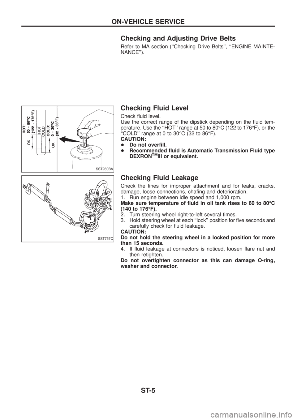
Checking Fluid Level
Check ¯uid level.
Use the correct range of the dipstick depending on the ¯uid tem-
perature. Use the ``HOT'' range at 50 to 80ÉC (122 to 176ÉF), or the
``COLD'' range at 0 to 30ÉC (32 to 86ÉF).
CAUTION:
+Do not over®ll.
+Recommended ¯uid is Automatic Transmission Fluid type
DEXRON
TMIII or equivalent.
Checking Fluid Leakage
Check the lines for improper attachment and for leaks, cracks,
damage, loose connections, cha®ng and deterioration.
1. Run engine between idle speed and 1,000 rpm.
Make sure temperature of ¯uid in oil tank rises to 60 to 80ÉC
(140 to 176ÉF).
2. Turn steering wheel right-to-left several times.
3. Hold steering wheel at each ``lock'' position for ®ve seconds and
carefully check for ¯uid leakage.
CAUTION:
Do not hold the steering wheel in a locked position for more
than 15 seconds.
4. If ¯uid leakage at connectors is noticed, loosen ¯are nut and
then retighten.
Do not overtighten connector as this can damage O-ring,
washer and connector.
SST280BA
SST757C
ON-VEHICLE SERVICE
ST-5
Page 1175 of 1226

Bleeding Hydraulic System
1. Raise front end of vehicle until wheels are clear of the ground.
2. Add ¯uid into oil tank to speci®ed level. Then, quickly turn steer-
ing wheel fully to right and left and lightly touch steering stop-
pers.
Repeat steering wheel operation until ¯uid level no longer
decreases.
3. Start engine.
Repeat step 2 above.
+Incomplete air bleeding will cause the following to occur. When
this happens, bleed air again.
a. Air bubbles in reservoir tank
b. Clicking noise in oil pump
c. Excessive buzzing in oil pump
Fluid noise may occur in the valve or oil pump. This is common
when the vehicle is stationary or while turning steering wheel
slowly. This does not affect performance or durability of the system.
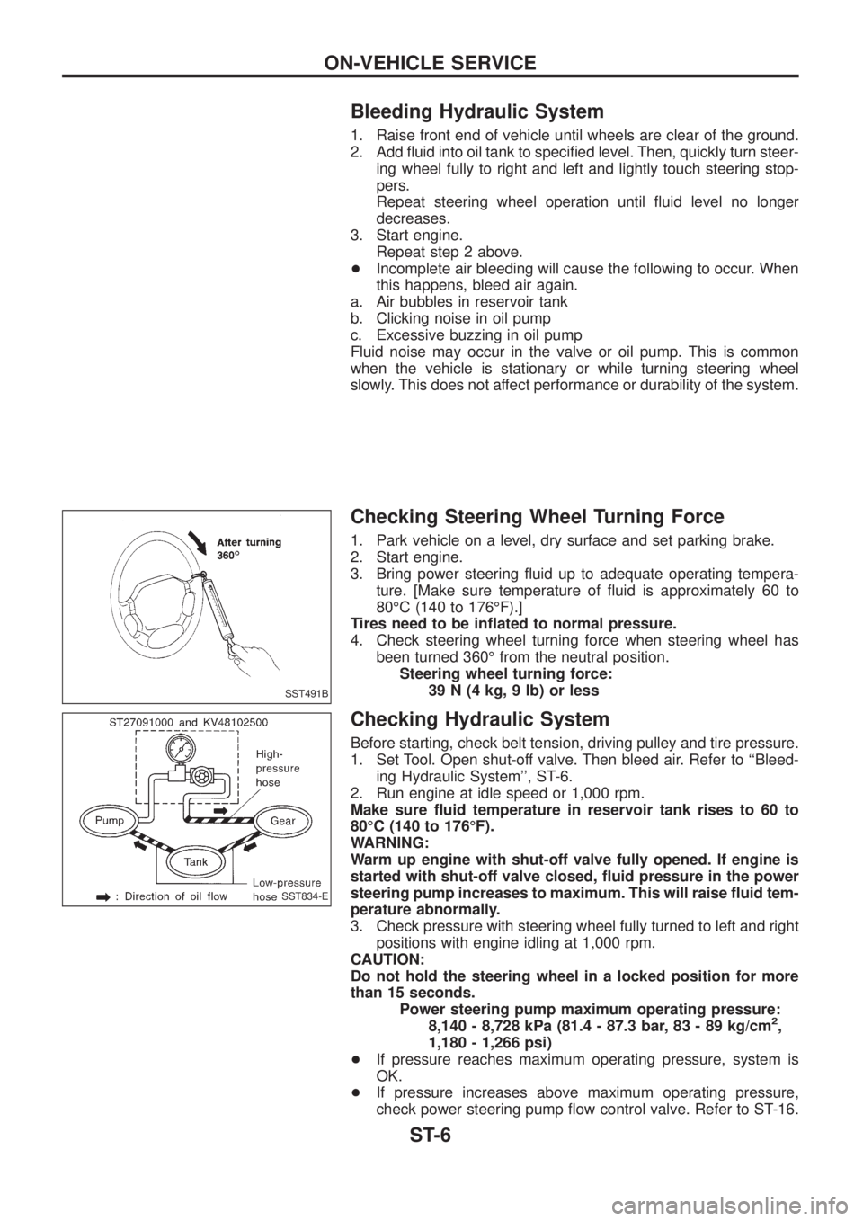
Checking Steering Wheel Turning Force
1. Park vehicle on a level, dry surface and set parking brake.
2. Start engine.
3. Bring power steering ¯uid up to adequate operating tempera-
ture. [Make sure temperature of ¯uid is approximately 60 to
80ÉC (140 to 176ÉF).]
Tires need to be in¯ated to normal pressure.
4. Check steering wheel turning force when steering wheel has
been turned 360É from the neutral position.
Steering wheel turning force:
39 N (4 kg, 9 lb) or less
Checking Hydraulic System
Before starting, check belt tension, driving pulley and tire pressure.
1. Set Tool. Open shut-off valve. Then bleed air. Refer to ``Bleed-
ing Hydraulic System'', ST-6.
2. Run engine at idle speed or 1,000 rpm.
Make sure ¯uid temperature in reservoir tank rises to 60 to
80ÉC (140 to 176ÉF).
WARNING:
Warm up engine with shut-off valve fully opened. If engine is
started with shut-off valve closed, ¯uid pressure in the power
steering pump increases to maximum. This will raise ¯uid tem-
perature abnormally.
3. Check pressure with steering wheel fully turned to left and right
positions with engine idling at 1,000 rpm.
CAUTION:
Do not hold the steering wheel in a locked position for more
than 15 seconds.
Power steering pump maximum operating pressure:
8,140 - 8,728 kPa (81.4 - 87.3 bar, 83 - 89 kg/cm
2,
1,180 - 1,266 psi)
+If pressure reaches maximum operating pressure, system is
OK.
+If pressure increases above maximum operating pressure,
check power steering pump ¯ow control valve. Refer to ST-16.
SST491B
SST834-E
ON-VEHICLE SERVICE
ST-6