Page 1174 of 1226

Checking and Adjusting Drive Belts
Refer to MA section (``Checking Drive Belts'', ``ENGINE MAINTE-
NANCE'').
Checking Fluid Level
Check ¯uid level.
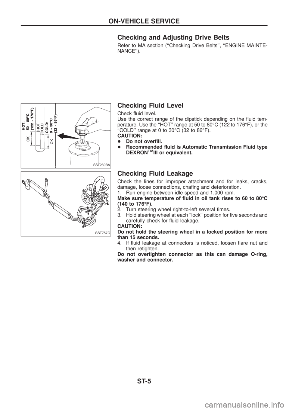
Use the correct range of the dipstick depending on the ¯uid tem-
perature. Use the ``HOT'' range at 50 to 80ÉC (122 to 176ÉF), or the
``COLD'' range at 0 to 30ÉC (32 to 86ÉF).
CAUTION:
+Do not over®ll.
+Recommended ¯uid is Automatic Transmission Fluid type
DEXRON
TMIII or equivalent.
Checking Fluid Leakage
Check the lines for improper attachment and for leaks, cracks,
damage, loose connections, cha®ng and deterioration.
1. Run engine between idle speed and 1,000 rpm.
Make sure temperature of ¯uid in oil tank rises to 60 to 80ÉC
(140 to 176ÉF).
2. Turn steering wheel right-to-left several times.
3. Hold steering wheel at each ``lock'' position for ®ve seconds and
carefully check for ¯uid leakage.
CAUTION:
Do not hold the steering wheel in a locked position for more
than 15 seconds.
4. If ¯uid leakage at connectors is noticed, loosen ¯are nut and
then retighten.
Do not overtighten connector as this can damage O-ring,
washer and connector.
SST280BA
SST757C
ON-VEHICLE SERVICE
ST-5
Page 1176 of 1226
4. If power steering pressure is below the maximum operating
pressure, slowly close shut-off valve and check pressure again.
CAUTION:
Do not close shut-off valve for more than 15 seconds.
+If pressure increases to maximum operating pressure, gear is
damaged. Refer to ``Removal and Installation'', ST-13.
+If pressure remains below maximum operating pressure, pump
is damaged. Refer to ``Disassembly'', ST-17.
5. After checking hydraulic system, remove Tool and add ¯uid as
necessary. Then completely bleed air out of system. Refer to
ST-6.
ON-VEHICLE SERVICE
Checking Hydraulic System (Cont'd)
ST-7
Page 1193 of 1226

TRANSFER
SECTION
TF
CONTENTS
PREPARATION................................................................1
Special Service Tools ..................................................1
Commercial Service Tools ...........................................2
NOISE, VIBRATION AND HARSHNESS (NVH)
TROUBLESHOOTING.....................................................3
NVH Troubleshooting Chart.........................................3
DESCRIPTION.................................................................4
Cross-sectional View ...................................................4
ON-VEHICLE SERVICE..................................................5
Replacing Oil Seal .......................................................5
Checking Position Switch ............................................7
REMOVAL AND INSTALLATION....................................8
Removal .......................................................................8
Installation ....................................................................8
TRANSFER GEAR CONTROL.......................................9
MAJOR OVERHAUL.....................................................10
Case Components .....................................................10
Gear Components ..................................................... 11Shift Control Components .........................................12
DISASSEMBLY..............................................................13
REPAIR FOR COMPONENT PARTS............................19
Mainshaft ...................................................................19
Front Drive Shaft .......................................................20
Counter Gear .............................................................21
Main Gear ..................................................................22
Front Case .................................................................24
Front Case Cover ......................................................24
Center Case...............................................................24
Bearing Retainer ........................................................25
Rear Case..................................................................25
Shift Control Components .........................................26
ASSEMBLY....................................................................27
SERVICE DATA AND SPECIFICATIONS (SDS)..........33
General Speci®cations ...............................................33
Inspection and Adjustment ........................................33
TF
Page 1194 of 1226

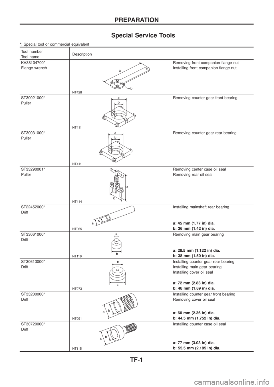
Special Service Tools
*: Special tool or commercial equivalent
Tool number
Tool nameDescription
KV38104700*
Flange wrench
NT428
Removing front companion ¯ange nut
Installing front companion ¯ange nut
ST30021000*
Puller
NT411
Removing counter gear front bearing
ST30031000*
Puller
NT411
Removing counter gear rear bearing
ST33290001*
Puller
NT414
Removing center case oil seal
Removing rear oil seal
ST22452000*
Drift
NT065
Installing mainshaft rear bearing
a: 45 mm (1.77 in) dia.
b: 36 mm (1.42 in) dia.
ST33061000*
Drift
NT116
Removing main gear bearing
a: 28.5 mm (1.122 in) dia.
b: 38 mm (1.50 in) dia.
ST30613000*
Drift
NT073
Installing counter gear rear bearing
Installing main gear bearing
Installing cover oil seal
a: 72 mm (2.83 in) dia.
b: 48 mm (1.89 in) dia.
ST33200000*
Drift
NT091
Installing counter gear front bearing
Removing cover oil seal
a: 60 mm (2.36 in) dia.
b: 44.5 mm (1.752 in) dia.
ST30720000*
Drift
NT115
Installing counter case oil seal
a: 77 mm (3.03 in) dia.
b: 55.5 mm (2.185 in) dia.
PREPARATION
TF-1
Page 1195 of 1226
Commercial Service Tools
Tool name Description
Puller
NT077
Removing front and rear companion ¯anges
Removing mainshaft rear bearing and clutch
gear
Removing L & H hub
Removing front drive shaft front bearing
Removing front drive shaft rear bearing
Removing main gear bearing
Drift
NT117
Installing shift shaft oil seal
a: 26 mm (1.02 in) dia.
b: 20 mm (0.79 in) dia.
c: 40 mm (1.57 in)
Drift
NT117
Installing L & H hub
a: 60 mm (2.36 in) dia.
b: 50 mm (1.97 in) dia.
c: 60 mm (2.36 in)
Drift
NT117
Installing clutch gear
a: 55 mm (2.17 in) dia.
b: 45 mm (1.77 in) dia.
c: 160 mm (6.30 in)
Drift
NT117
Installing rear oil seal
a: 75 mm (2.95 in) dia.
b: 67 mm (2.64 in) dia.
c: 60 mm (2.36 in)
PREPARATION
TF-2
Page 1196 of 1226
NVH Troubleshooting Chart
Use the chart below to help you ®nd the cause of the problem. The numbers indicate the order of the inspec-
tion. If necessary, repair or replace these parts.
TRANSFER
Reference page
Refer to MA section (``Checking Transfer Fluid'',
``CHASSIS AND BODY MAINTENANCE'').
TF-10
TF-10
TF-10, TF-12
TF-12
TF-11
TF-11
TF-11
TF-11
SUSPECTED PARTS (Possible cause)
FLUID (Level low)
FLUID (Wrong)
FLUID (Level too high)
LIQUID GASKET (Damaged)
OIL SEAL (Worn or damaged)
CHECK SPRING AND CHECK BALL (Worn or damaged)
SHIFT FORK (Worn)
GEAR (Worn or damaged)
BEARING (Worn or damaged)
BAULK RING (Worn or damaged)
SHIFTING INSERT (Damaged)
SymptomNoise 1 2 3 3
Fluid leakage3122
Hard to shift or will not shift 1 1 2 2
Jumps out of gear 1 2 2
NOISE, VIBRATION AND HARSHNESS (NVH) TROUBLESHOOTING
TF-3
Page 1208 of 1226
9. Pull out clutch gear and mainshaft rear bearing.
10. Remove 2-4 coupling sleeve with 2-4 shift fork.
11. Remove front drive shaft assembly, drive chain and front drive
sprocket by tapping front end of front drive shaft.
12. Remove bolts securing bearing retainer and then remove bear-
ing retainer.
SMT111B
SMT112B
SMT113B
SMT115B
DISASSEMBLY
TF-15
Page 1209 of 1226
13. Remove bolts securing center case to front case and then
separate center case and front case.
14. Measure end play of low gear.
Standard:
0.20 - 0.35 mm (0.0079 - 0.0138 in)
Refer to SDS, TF-33.
+If end play is beyond the maximum value, check low gear and
L & H hub for wear.
15. Disassemble center case assembly.
a. Remove snap ring from mainshaft.
b. Pull out low gear with L & H hub.
c. Remove mainshaft by tapping front end of mainshaft.
SMT116B
SMT117B
SMT118B
SMT119B
SMT120B
DISASSEMBLY
TF-16