2006 NISSAN PATROL main
[x] Cancel search: mainPage 1103 of 1226
Removal
CAUTION:
+Before removing the rear axle, disconnect the ABS wheel
sensor from the assembly. Then move it away from the
axle. Failure to do so may result in damage to the sensor
wires and the sensor becoming inoperative.
+Wheel bearing does not require maintenance.
+If growling noise is emitted from wheel bearing during
operation, replace wheel bearing assembly.
+If the wheel bearing assembly is removed, it must be renewed.
The old assembly must not be re-used.
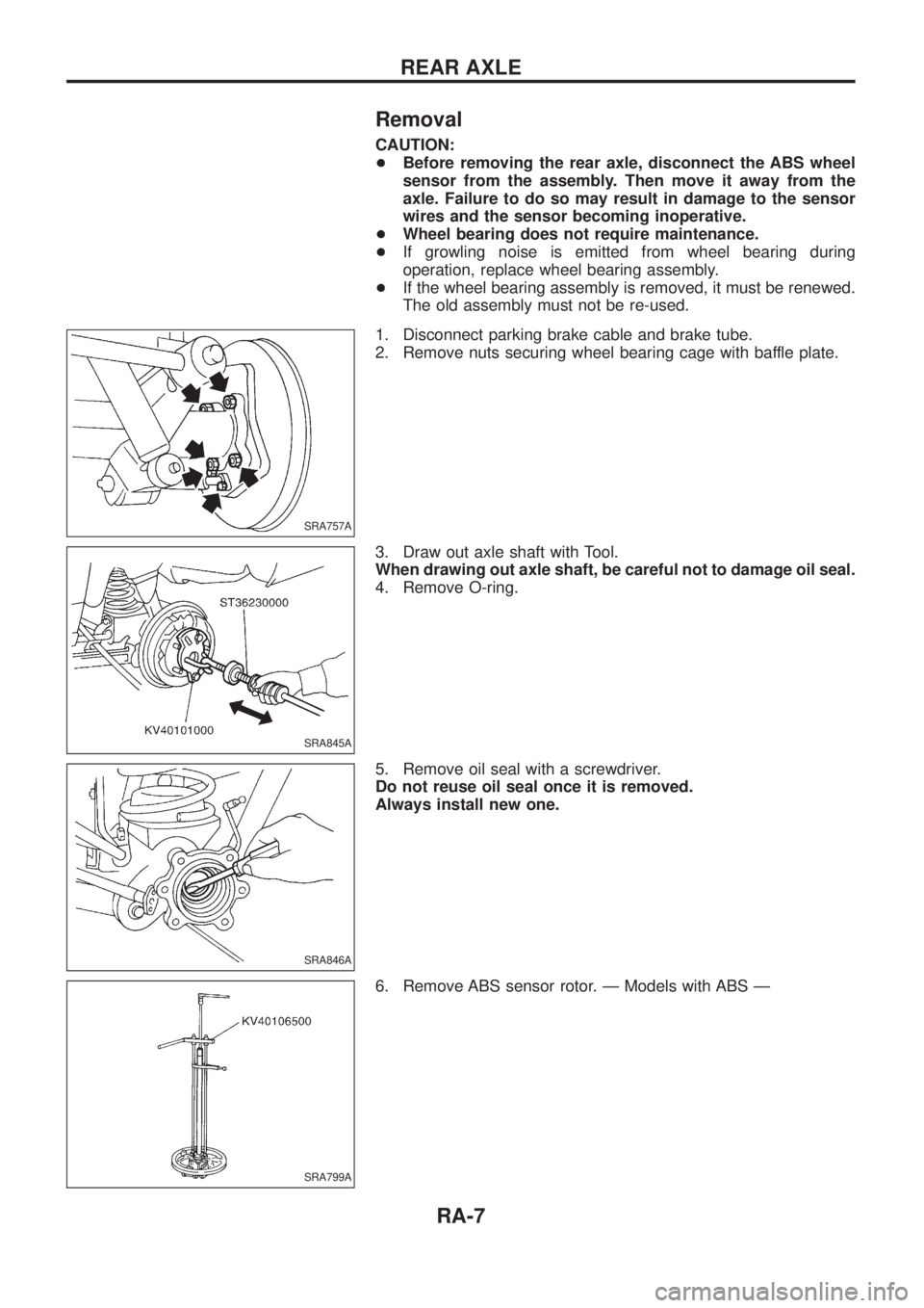
1. Disconnect parking brake cable and brake tube.
2. Remove nuts securing wheel bearing cage with baffle plate.
3. Draw out axle shaft with Tool.
When drawing out axle shaft, be careful not to damage oil seal.
4. Remove O-ring.
5. Remove oil seal with a screwdriver.
Do not reuse oil seal once it is removed.
Always install new one.
6. Remove ABS sensor rotor. Ð Models with ABS Ð
SRA757A
SRA845A
SRA846A
SRA799A
REAR AXLE
RA-7
Page 1112 of 1226
System Components
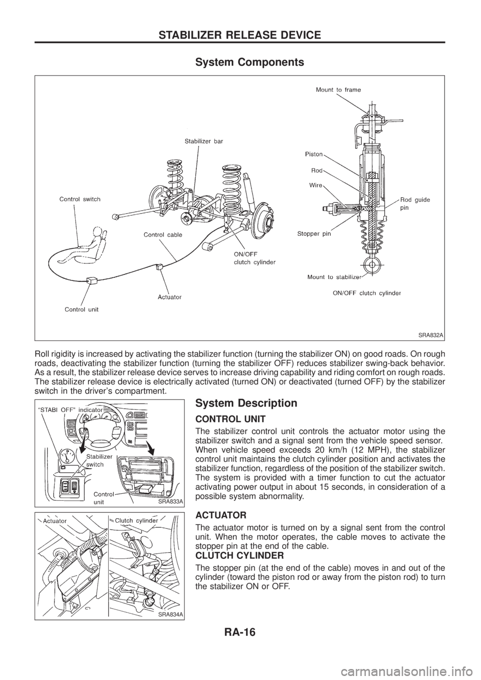
Roll rigidity is increased by activating the stabilizer function (turning the stabilizer ON) on good roads. On rough
roads, deactivating the stabilizer function (turning the stabilizer OFF) reduces stabilizer swing-back behavior.
As a result, the stabilizer release device serves to increase driving capability and riding comfort on rough roads.
The stabilizer release device is electrically activated (turned ON) or deactivated (turned OFF) by the stabilizer
switch in the driver's compartment.
System Description
CONTROL UNIT
The stabilizer control unit controls the actuator motor using the
stabilizer switch and a signal sent from the vehicle speed sensor.
When vehicle speed exceeds 20 km/h (12 MPH), the stabilizer
control unit maintains the clutch cylinder position and activates the
stabilizer function, regardless of the position of the stabilizer switch.
The system is provided with a timer function to cut the actuator
activating power output in about 15 seconds, in consideration of a
possible system abnormality.
ACTUATOR
The actuator motor is turned on by a signal sent from the control
unit. When the motor operates, the cable moves to activate the
stopper pin at the end of the cable.
CLUTCH CYLINDER
The stopper pin (at the end of the cable) moves in and out of the
cylinder (toward the piston rod or away from the piston rod) to turn
the stabilizer ON or OFF.
SRA832A
SRA833A
SRA834A
STABILIZER RELEASE DEVICE
RA-16
Page 1122 of 1226
RESTRAINT SYSTEM
SECTION
RS
CONTENTS
PRECAUTION..................................................................1
Supplemental Restraint System (SRS) ``AIR
BAG'' and ``SEAT BELT PRE-TENSIONER''...............1
SEAT BELTS...................................................................2
Front Seat Belt.............................................................3
Rear Seat Belt .............................................................5
3rd Seat Belt ................................................................7
SUPPLEMENTAL RESTRAINT SYSTEM (SRS)............8
Precautions for SRS ``AIR BAG'' and ``Seat Belt
Pre-tensioner'' Service.................................................8
Special Service Tools ..................................................8
Description .................................................................10
SRS Component Parts Location ...............................10
Maintenance Items .................................................... 11
Removal and Installation Ð Diagnosis Sensor
Unit and Seat Belt Pre-tensioner...............................12
Removal and Installation Ð Air Bag Module and
Spiral Cable ...............................................................13
Removal Ð Air Bag Module and Spiral Cable ..........13
Removal Ð Front Passenger Air Bag Module ..........14
Installation Ð Air Bag Module and Spiral Cable .......16Installation Ð Front Passenger Air Bag Module .......16
Disposal of Air Bag Module and Seat Belt Pre-
tensioner ....................................................................17
TROUBLE DIAGNOSES Ð Supplemental
Restraint System (SRS)...............................................22
Trouble Diagnoses Introduction.................................22
How to Perform Trouble Diagnoses for Quick
and Accurate Repair ..................................................24
Schematic ..................................................................26
Wiring Diagram Ð SRS Ð ........................................27
SRS Operation Check ...............................................30
Trouble Diagnoses with CONSULT ...........................32
Trouble Diagnoses without CONSULT ......................39
Trouble Diagnoses: ``AIR BAG'' Warning Lamp
Does Not Turn Off .....................................................43
Trouble Diagnoses: ``AIR BAG'' Warning Lamp
Does Not Turn On .....................................................43
Trouble Diagnoses: SRS Does Not Enter
Diagnosis Mode Using Door Switch ..........................44
COLLISION DIAGNOSIS...............................................45
When you read wiring diagrams:
+Read GI section, ``HOW TO READ WIRING DIAGRAMS''.
+See EL section, ``POWER SUPPLY ROUTING'' for power distribution circuit.
When you perform trouble diagnoses, read GI section, ``HOW TO FOLLOW FLOW
CHART IN TROUBLE DIAGNOSES'' and ``HOW TO PERFORM EFFICIENT DIAGNOSIS
FOR AN ELECTRICAL INCIDENT''.
RS
Page 1123 of 1226
Supplemental Restraint System (SRS) ``AIR
BAG'' and ``SEAT BELT PRE-TENSIONER''
The Supplemental Restraint System such as ``AIR BAG'' and ``SEAT BELT PRE-TENSIONER'' used along with
a seat belt, helps to reduce the risk or severity of injury to the driver and front passenger in a frontal collision.
The SRS composition which is available to NISSAN MODEL Y61 is as follows (The composition varies
according to the destination.):
Driver air bag module (located in the center of the steering wheel), front passenger air bag module (located
on the instrument panel on passenger side), seat belt pre-tensioner, a diagnosis sensor unit, warning lamp,
wiring harness and spiral cable.
WARNING:
+To avoid rendering the SRS inoperative, which could increase the risk of personal injury or death
in the event of a collision which would result in air bag in¯ation, all maintenance must be performed
by an authorized NISSAN dealer.
+Improper maintenance, including incorrect removal and installation of the SRS, can lead to per-
sonal injury caused by unintentional activation of the system.
+Do not use electrical test equipment on any circuit related to the SRS unless instructed to in this
Service Manual. Spiral cable and wiring harnesses covered with yellow insulation either just before
the harness connectors or for the complete harness are related to the SRS.
PRECAUTION
RS-1
Page 1133 of 1226
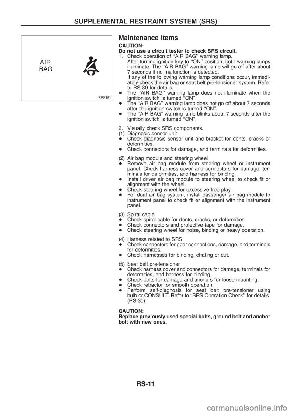
Maintenance Items
CAUTION:
Do not use a circuit tester to check SRS circuit.
1. Check operation of ``AIR BAG'' warning lamp.
After turning ignition key to ``ON'' position, both warning lamps
illuminate. The ``AIR BAG'' warning lamp will go off after about
7 seconds if no malfunction is detected.
If any of the following warning lamp conditions occur, immedi-
ately check the air bag or seat belt pre-tensioner system. Refer
to RS-30 for details.
+The ``AIR BAG'' warning lamp does not illuminate when the
ignition switch is turned ``ON''.
+The ``AIR BAG'' warning lamp does not go off about 7 seconds
after the ignition switch is turned ``ON''.
+The ``AIR BAG'' warning lamp blinks about 7 seconds after the
ignition switch is turned ``ON''.
2. Visually check SRS components.
(1) Diagnosis sensor unit
+Check diagnosis sensor unit and bracket for dents, cracks or
deformities.
+Check connectors for damage, and terminals for deformities.
(2) Air bag module and steering wheel
+Remove air bag module from steering wheel or instrument
panel. Check harness cover and connectors for damage, ter-
minals for deformities, and harness for binding.
+Install driver air bag module to steering wheel to check ®t or
alignment with the wheel.
+Check steering wheel for excessive free play.
+For dual air bag system, install passenger air bag module to
instrument panel to check ®t or alignment with the instrument
panel.
(3) Spiral cable
+Check spiral cable for dents, cracks, or deformities.
+Check connectors and protective tape for damage.
+Check steering wheel for noise, binding or heavy operation.
(4) Harness related to SRS
+Check connectors for poor connections, damage, and terminals
for deformities.
+Check harnesses for binding, cha®ng or cut.
(5) Seat belt pre-tensioner
+Check harness cover and connectors for damage, terminals for
deformities, and harness for binding.
+Check belts for damage and anchors for loose mounting.
+Check retractor for smooth operation.
+Perform self-diagnosis for seat belt pre-tensioner using
bulb or CONSULT. Refer to ``SRS Operation Check'' for details.
(RS-30)
CAUTION:
Replace previously used special bolts, ground bolt and anchor
bolt with new ones.
SRS451
SUPPLEMENTAL RESTRAINT SYSTEM (SRS)
RS-11
Page 1158 of 1226
![NISSAN PATROL 2006 Service Manual 10. Check that no self-diagnostic failure is detected on ``SELF-
DIAG [PAST].
NOTE:
Past malfunction for seat belt pre-tensioner system will not be
displayed on ``SELF-DIAG [PAST].
11. Touch ``BAC NISSAN PATROL 2006 Service Manual 10. Check that no self-diagnostic failure is detected on ``SELF-
DIAG [PAST].
NOTE:
Past malfunction for seat belt pre-tensioner system will not be
displayed on ``SELF-DIAG [PAST].
11. Touch ``BAC](/manual-img/5/57368/w960_57368-1157.png)
10. Check that no self-diagnostic failure is detected on ``SELF-
DIAG [PAST]''.
NOTE:
Past malfunction for seat belt pre-tensioner system will not be
displayed on ``SELF-DIAG [PAST]''.
11. Touch ``BACK'' key of CONSULT until ``SELECT SYSTEM''
appears in order to return to User mode from Diagnosis mode,
turn off CONSULT, then disconnect CONSULT.
12. Turn ignition switch ``OFF''.
13. Go to ``SRS Operation Check'', page RS-30 to check SRS
operation by using ``AIR BAG'' warning lamp with User mode.
DIAGNOSTIC PROCEDURE 4 (Continued from
DIAGNOSTIC PROCEDURE 2) (
with CONSULT)
Inspecting SRS malfunctioning record
Is it the ®rst time for maintenance of
SRS?
Ye s
cNo
Self-diagnostic failure
``SELF-DIAG [PAST]'' (pre-
viously stored in the
memory) might not be
erased after repair.
Go to DIAGNOSTIC PRO-
CEDURE 3, step 8 (RS-
34).
GO TO DIAGNOSTIC PROCEDURE 5
(RS-36).
DIAGNOSTIC PROCEDURE 5
Inspecting SRS intermittent problem by using CONSULT Ð
Diagnosis mode
1. Turn ignition switch ``OFF''.
2. Connect ``CONSULT'' to Data link connector.
3. Turn ignition switch ``ON''.
4. Touch ``START''.
SRS062
SRS468
SRS046
.
TROUBLE DIAGNOSES Ð Supplemental Restraint System (SRS)
Trouble Diagnoses with CONSULT (Cont'd)
RS-36
Page 1164 of 1226
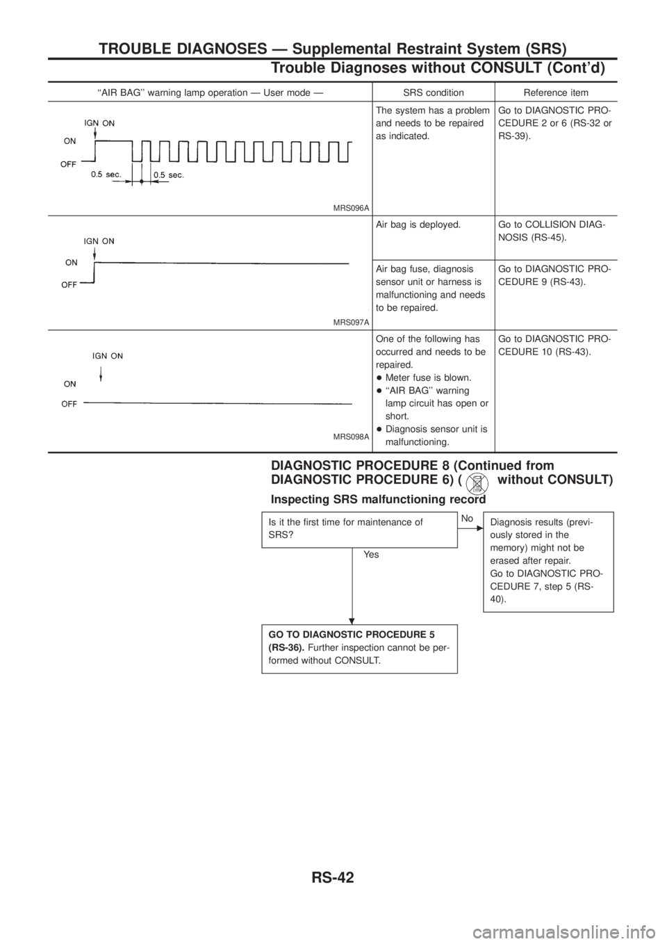
``AIR BAG'' warning lamp operation Ð User mode Ð SRS condition Reference item
MRS096A
The system has a problem
and needs to be repaired
as indicated.Go to DIAGNOSTIC PRO-
CEDURE 2 or 6 (RS-32 or
RS-39).
MRS097A
Air bag is deployed. Go to COLLISION DIAG-
NOSIS (RS-45).
Air bag fuse, diagnosis
sensor unit or harness is
malfunctioning and needs
to be repaired.Go to DIAGNOSTIC PRO-
CEDURE 9 (RS-43).
MRS098A
One of the following has
occurred and needs to be
repaired.
+Meter fuse is blown.
+``AIR BAG'' warning
lamp circuit has open or
short.
+Diagnosis sensor unit is
malfunctioning.Go to DIAGNOSTIC PRO-
CEDURE 10 (RS-43).
DIAGNOSTIC PROCEDURE 8 (Continued from
DIAGNOSTIC PROCEDURE 6) (
without CONSULT)
Inspecting SRS malfunctioning record
Is it the ®rst time for maintenance of
SRS?
Ye s
cNo
Diagnosis results (previ-
ously stored in the
memory) might not be
erased after repair.
Go to DIAGNOSTIC PRO-
CEDURE 7, step 5 (RS-
40).
GO TO DIAGNOSTIC PROCEDURE 5
(RS-36).Further inspection cannot be per-
formed without CONSULT.
.
TROUBLE DIAGNOSES Ð Supplemental Restraint System (SRS)
Trouble Diagnoses without CONSULT (Cont'd)
RS-42
Page 1170 of 1226
Supplemental Restraint System (SRS) ``AIR
BAG'' and ``SEAT BELT PRE-TENSIONER''
The Supplemental Restraint System such as ``AIR BAG'' and ``SEAT BELT PRE-TENSIONER'' used along with
a seat belt, helps to reduce the risk or severity of injury to the driver and front passenger in a frontal collision.
The SRS system composition which is available to NISSAN MODEL Y61 is as follows (The composition var-
ies according to the destination.):
Driver air bag module (located in the center of the steering wheel), front passenger air bag module (located
on the instrument panel on passenger side), seat belt pre-tensioner, a diagnosis sensor unit, warning lamp,
wiring harness and spiral cable.
Information necessary to service the system safely is included in theRS sectionof this Service Manual.
WARNING:
+To avoid rendering the SRS inoperative, which could increase the risk of personal injury or death
in the event of a collision which would result in air bag in¯ation, all maintenance must be performed
by an authorized NISSAN dealer.
+Improper maintenance, including incorrect removal and installation of the SRS, can lead to per-
sonal injury caused by unintentional activation of the system. For removal of Spiral Cable and Air
Bag Module, see the RS section.
+Do not use electrical test equipment on any circuit related to the SRS unless instructed to in this
Service Manual. Spiral cable and wiring harnesses covered with yellow insulation either just before
the harness connectors or for the complete harness are related to the SRS.
Precautions for Steering System
+Before disassembly, thoroughly clean the outside of the unit.
+Disassembly should be done in a clean work area. It is important to prevent the internal parts from
becoming contaminated by dirt or other foreign matter.
+Place disassembled parts in order, on a parts rack, for easier and proper assembly.
+Use nylon cloths or paper towels to clean the parts; common shop rags can leave lint that might
interfere with their operation.
+Before inspection or reassembly, carefully clean all parts with a general purpose, non-¯ammable
solvent.
+Before assembly, apply a coat of recommended ATF* to hydraulic parts. Vaseline may be applied
to O-rings and seals. Do not use any grease.
+Replace all gaskets, seals and O-rings. Avoid damaging O-rings, seals and gaskets during instal-
lation. Perform functional tests whenever designated.
*: Automatic Transmission Fluid type DEXRON
TMIII or equivalent
Special Service Tools
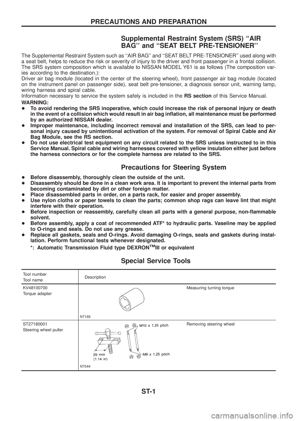
Tool number
Tool nameDescription
KV48100700
Torque adapter
NT169
Measuring turning torque
ST27180001
Steering wheel puller
NT544
Removing steering wheel
PRECAUTIONS AND PREPARATION
ST-1