Page 1032 of 1226
b. Place dial indicator on front end of reverse idler shaft.
c. Put straightedge on front surface of OD gear case as a stop-
per of reverse idler shaft.
d. Move reverse idler shaft up and down and measure reverse
idler gear end play.
Reverse idler gear end play:
0.30 - 0.53 mm (0.0118 - 0.0209 in)
e. If not within speci®cation, replace reverse idler rear thrust
washer with the other (A or B) and check again.
7. Install mainshaft and counter gear on adapter plate and main
drive gear on mainshaft.
a. Mount adapter plate on vise and apply multi-purpose grease to
counter gear rear bearing.
b. Install mainshaft a little on mainshaft front bearing.
+To allow for installation of counter gear, do not install
mainshaft completely.
c. Install counter gear on counter gear rear bearing and install
main drive gear, pilot bearing and spacer on mainshaft.
SMT433A
SMT438A
SMT440A
SMT441A
ASSEMBLY
Gear Components (Cont'd)
MT-25
Page 1033 of 1226
+When installing counter gear into counter gear rear
bearing, push up on upper roller of counter gear rear bear-
ing with screwdriver.
d. Install mainshaft and counter gear completely by tapping rear
side of adapter plate and pulling mainshaft.
8. Install rear side components on mainshaft and counter gear.
a. Install OD gear bushing while pushing on the front of counter
gear.
b. Install OD main gear.
+Pay attention to direction of OD main gear. (B is wider than
A as shown at left.)
c. Install adapter plate with gear assembly onto transmission
case.
d. Install OD gear needle bearing and then install OD counter gear
and reverse idler shaft.
e. Install reverse cone.
SMT442A
SMT443A
SMT444AA
SMT580AB
SMT582AA
ASSEMBLY
Gear Components (Cont'd)
MT-26
Page 1034 of 1226
f. Install insert springs and reverse baulk ring on OD coupling
sleeve. Then install them and OD baulk ring on OD counter
gear.
+Pay attention to direction of OD coupling sleeve.
g. Install reverse counter gear.
h. Install reverse gear needle bearing and then install reverse
main gear, reverse idler gear and reverse idler thrust washers.
i. Install reverse hub and mainshaft spacer.
+Pay attention to direction of reverse hub.
j. Install counter gear rear end bearing.
k. Separate adapter plate from transmission case and mount
adapter plate on vice again.
SMT571AA
SMT583A
SMT584AA
SMT585AA
SMT828C
ASSEMBLY
Gear Components (Cont'd)
MT-27
Page 1035 of 1226
l. Select proper mainshaft C-ring to minimize clearance of
groove.
Allowable clearance of groove:
0 - 0.1 mm (0 - 0.004 in)
Mainshaft C-ring:
Refer to SDS, MT-34.
m. Install selected C-ring, C-ring holder and mainshaft rear snap
ring.
n. Select proper counter gear rear snap ring to minimize clear-
ance of groove.
Allowable clearance of groove:
0 - 0.1 mm (0 - 0.004 in)
Counter gear rear snap ring:
Refer to SDS, MT-34.
o. Install selected counter gear rear snap ring.
p. Install reverse coupling sleeve.
+Pay attention to its direction.
q. Measure each gear end play as a ®nal check. Refer to
``DISASSEMBLY'', MT-15.
SMT829C
SMT830C
SMT831C
SMT832C
SMT833C
ASSEMBLY
Gear Components (Cont'd)
MT-28
Page 1037 of 1226
7. Install stopper ring and main drive bearing snap ring.
8. Install front cover and gasket.
+Apply sealant to thread of 3 bolts shown left.
9. Apply sealant to mating surface of adapter plate.
10. Install OD gear case together with striking arm.
11. Install retaining pin into striking arm.
12. Install return spring and check ball and then install control hous-
ing.
+Apply sealant to mating surface of OD gear case.
SMT371A
SMT459A
SMT444B
SMT439B
SMT445B
ASSEMBLY
Case Components (Cont'd)
MT-30
Page 1039 of 1226
General Speci®cations
Applied modelRD28ETi
4WD
Transmission FS5R30A
Number of speed 5
Transmission control Floor direct
Shift pattern
Synchromesh type Warner
Gear ratio
1st 4.061
2nd 2.357
3rd 1.490
4th 1.000
OD 0.862
Reverse 4.125
Number of teeth
Mainshaft
Drive 20
1st 32
2nd 30
3rd 28
OD 23
Reverse 30
Countershaft
Drive 33
1st 13
2nd 21
3rd 31
OD 44
Reverse 12
Reverse idler gear 22
Oil capacity!(Imp pt) 5.1 (9)
Remarks2nd & 3rd double baulk ring
type synchronizer
Reverse breaking mechanism type
SERVICE DATA AND SPECIFICATIONS (SDS)
MT-32
Page 1040 of 1226

Inspection and Adjustment
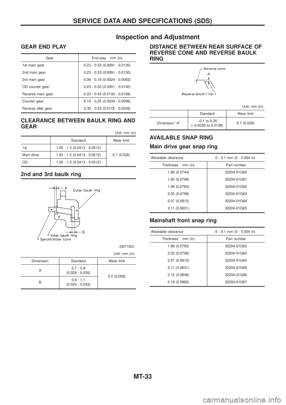
GEAR END PLAY
Gear End play mm (in)
1st main gear 0.23 - 0.33 (0.0091 - 0.0130)
2nd main gear 0.23 - 0.33 (0.0091 - 0.0130)
3rd main gear 0.06 - 0.16 (0.0024 - 0.0063)
OD counter gear 0.23 - 0.33 (0.0091 - 0.0130)
Reverse main gear 0.33 - 0.43 (0.0130 - 0.0169)
Counter gear 0.10 - 0.25 (0.0039 - 0.0098)
Reverse idler gear 0.30 - 0.53 (0.0118 - 0.0209)
CLEARANCE BETWEEN BAULK RING AND
GEAR
Unit: mm (in)
Standard Wear limit
1st 1.05 - 1.3 (0.0413 - 0.0512)
0.7 (0.028) Main drive 1.05 - 1.3 (0.0413 - 0.0512)
OD 1.05 - 1.3 (0.0413 - 0.0512)
2nd and 3rd baulk ring
SMT742C
Unit: mm (in)
Dimension Standard Wear limit
A0.7 - 0.9
(0.028 - 0.035)
0.2 (0.008)
B0.6 - 1.1
(0.024 - 0.043)
DISTANCE BETWEEN REAR SURFACE OF
REVERSE CONE AND REVERSE BAULK
RING
Unit: mm (in)
Standard Wear limit
Dimension ``A''þ0.1 to 0.35
(þ0.0039 to 0.0138)0.7 (0.028)
AVAILABLE SNAP RING
Main drive gear snap ring
Allowable clearance 0 - 0.1 mm (0 - 0.004 in)
Thickness mm (in) Part number
1.89 (0.0744) 32204-01G60
1.95 (0.0768) 32204-01G61
1.99 (0.0783) 32204-01G62
2.03 (0.0799) 32204-01G63
2.07 (0.0815) 32204-01G64
2.11 (0.0831) 32204-01G65
Mainshaft front snap ring
Allowable clearance 0 - 0.1 mm (0 - 0.004 in)
Thickness mm (in) Part number
1.99 (0.0783) 32204-01G62
2.03 (0.0799) 32204-01G63
2.07 (0.0815) 32204-01G64
2.11 (0.0831) 32204-01G65
2.15 (0.0846) 32204-01G66
2.19 (0.0862) 32204-01G67
SERVICE DATA AND SPECIFICATIONS (SDS)
MT-33
Page 1041 of 1226

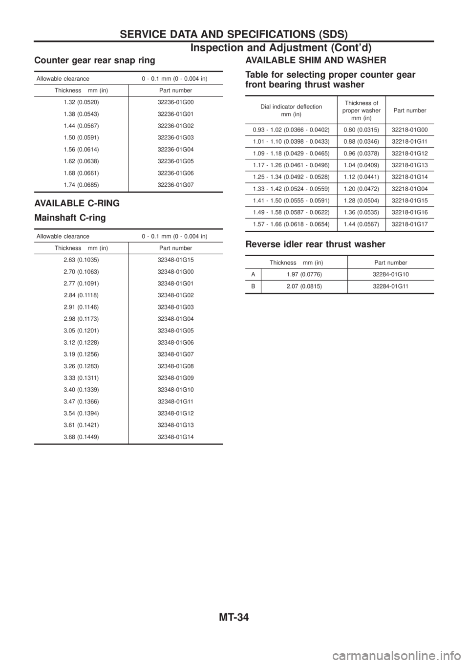
Counter gear rear snap ring
Allowable clearance 0 - 0.1 mm (0 - 0.004 in)
Thickness mm (in) Part number
1.32 (0.0520) 32236-01G00
1.38 (0.0543) 32236-01G01
1.44 (0.0567) 32236-01G02
1.50 (0.0591) 32236-01G03
1.56 (0.0614) 32236-01G04
1.62 (0.0638) 32236-01G05
1.68 (0.0661) 32236-01G06
1.74 (0.0685) 32236-01G07
AVAILABLE C-RING
Mainshaft C-ring
Allowable clearance 0 - 0.1 mm (0 - 0.004 in)
Thickness mm (in) Part number
2.63 (0.1035) 32348-01G15
2.70 (0.1063) 32348-01G00
2.77 (0.1091) 32348-01G01
2.84 (0.1118) 32348-01G02
2.91 (0.1146) 32348-01G03
2.98 (0.1173) 32348-01G04
3.05 (0.1201) 32348-01G05
3.12 (0.1228) 32348-01G06
3.19 (0.1256) 32348-01G07
3.26 (0.1283) 32348-01G08
3.33 (0.1311) 32348-01G09
3.40 (0.1339) 32348-01G10
3.47 (0.1366) 32348-01G11
3.54 (0.1394) 32348-01G12
3.61 (0.1421) 32348-01G13
3.68 (0.1449) 32348-01G14
AVAILABLE SHIM AND WASHER
Table for selecting proper counter gear
front bearing thrust washer
Dial indicator de¯ection
mm (in)Thickness of
proper washer
mm (in)Part number
0.93 - 1.02 (0.0366 - 0.0402) 0.80 (0.0315) 32218-01G00
1.01 - 1.10 (0.0398 - 0.0433) 0.88 (0.0346) 32218-01G11
1.09 - 1.18 (0.0429 - 0.0465) 0.96 (0.0378) 32218-01G12
1.17 - 1.26 (0.0461 - 0.0496) 1.04 (0.0409) 32218-01G13
1.25 - 1.34 (0.0492 - 0.0528) 1.12 (0.0441) 32218-01G14
1.33 - 1.42 (0.0524 - 0.0559) 1.20 (0.0472) 32218-01G04
1.41 - 1.50 (0.0555 - 0.0591) 1.28 (0.0504) 32218-01G15
1.49 - 1.58 (0.0587 - 0.0622) 1.36 (0.0535) 32218-01G16
1.57 - 1.66 (0.0618 - 0.0654) 1.44 (0.0567) 32218-01G17
Reverse idler rear thrust washer
Thickness mm (in) Part number
A 1.97 (0.0776) 32284-01G10
B 2.07 (0.0815) 32284-01G11
SERVICE DATA AND SPECIFICATIONS (SDS)
Inspection and Adjustment (Cont'd)
MT-34