Page 237 of 364
AC405884AB
Steering wheel
Steering column assembly
Electric power
steering-ECU
Motor
Torque sensor
Tie-rod end
Yoke bearing
Steering gearDash panel cover
GENER
A L IN FORMA T ION
POWER ST E E RING37-4
Page 238 of 364

CONSTRUCTION DESCRIPTION
POWER STEERING37-5
CONSTRUCTION DESCRIPTION
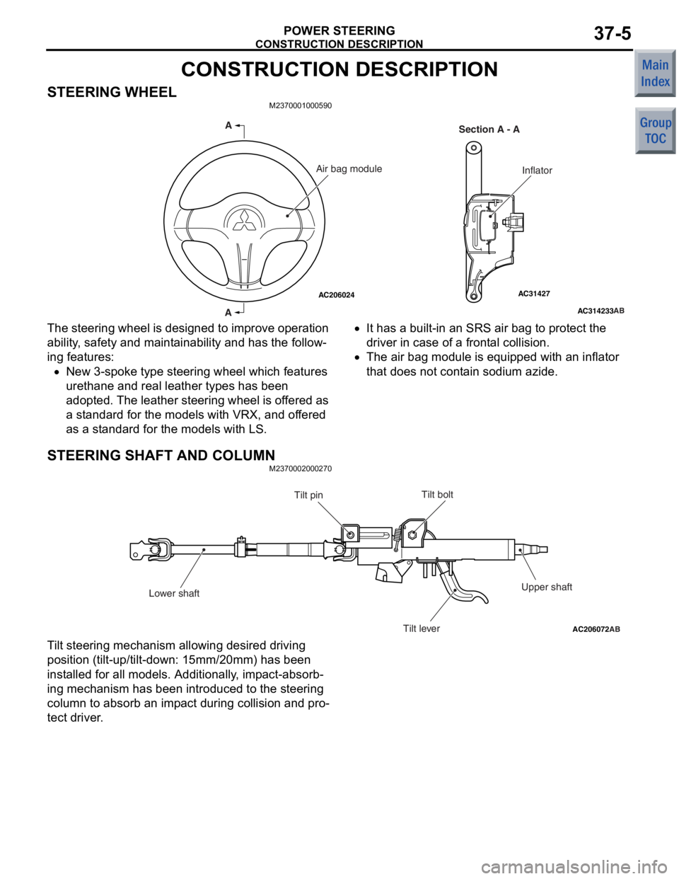
STEERING WHEELM2370001000590
AC314233
AC31427AC206024AB
A
A Section A - A
InflatorAir bag module
The steering wh
eel is de sig ned to impro v e operat ion
ability
, safety and main t a inabilit y and has the follow
-
ing features:
•New 3-spoke type stee ring whe e l which fe atures
uret
hane a nd real lea t her types has been
ado
pted. The leather stee ring wh eel is o f fere d as
a st
a ndard f o r the models with VRX, and of fered
as a st
an dard for the models with LS.
•It ha s a built-in a n SRS a i r ba g to pro t ect t he
driv
er in c a s e of a front a l c o ll is i o n.
•The air b ag mo dule is equip ped wit h an inflat or
tha
t does not cont ain sod i um azide.
STEERING SHAFT AND COLUMN
M23700020 0027 0
AC206072AB
Tilt bolt
Tilt pin
Lower shaft Tilt leverUpper shaft
T
i lt steering mecha n ism allowing desired d r iving
position
(tilt -up/tilt-down: 1 5 mm/20mm) ha s be en
inst
alled for all mo dels. Additiona lly , imp a ct-absorb
-
ing mechanism h a s be en in troduced to the steering
colu
mn t o absorb an imp a ct during collision an d pro
-
te c t dri v er .
Page 240 of 364

ELECTRICAL POWER STEERING
POWER STEERING37-7
ELECTRICAL POWER STEERING
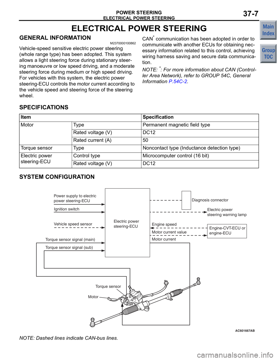
GENERAL INFORMATIONM2370000100862
Vehicle-speed sensitive electric power steering
(whole range type) has been adopted. This system
allows a light steering force during stationary steer
-
ing manoeuvre or low speed driving, and a moderate
steering force during medium or high speed driving.
For vehicles with this system, the electric power
steering-ECU controls the motor current according to
the vehicle speed and steering force of the steering
wheel.
CAN* communication has been adopted in order to
communicate with another ECUs for obtaining nec
-
essary information related to this control, achieving
wiring harness saving and secure data communica
-
tion.
NOTE: *: For more information about CAN (Control-
ler Area Network), refer to GROUP 54C, General
Information
P.54C-2.
SPECIFICATIONS
ItemSpecification
MotorTy p ePermanent magnetic field type
Rated voltage (V)DC12
Rated current (A)50
Torque sensorTy p eNoncontact type (Inductance detection type)
Electric power
steering-ECUControl typeMicrocomputer control (16 bit)
Rated voltage (V)DC12
SYSTEM CONFIGURATION
AC601667AB
Electric power
steering-ECU
Ignition switch
Power supply to electric
power steering-ECU
Vehicle speed sensor
Motor Motor current value Engine speed
Torque sensor signal (main) Electric power
steering warning lamp
Diagnosis connector
Motor current
Torque sensor
Torque sensor signal (sub) Engine-CVT-ECU or
engine-ECU
NO
TE: Dash ed lines indicat e CAN-bu s lines.
Page 242 of 364
ELECTRICAL POWER STEERING
POWER STEERING37-9
STEERING GEAR
M2370003000239
AC208175
AC208174AC206443AC
NeutralSub
Torque sensor
Steered to leftMain
Steered to right
Output voltage (V)
Torque sensor characteristic chart
52.5
The torqu e sensor which detect s a opera t ed force of
the steerin
g wheel is inst alled in the stee ring g ear .
Whe
n th e st eer in g whe e l is tu rn ed , t h e ste e ring f o rce
is d
e tected by the to rque sensor . At the same time,
2-way supp
ly volt a ge signa l (main and sub ) are input
to the e
l ectric power steerin g-ECU.
MOT O RM237000 1 1 0003 6
AC208523
AC206443
AC207634
AB
View AMotor
Motor
View A
The mot
o r is inst alled in th e steering gea r . The ste e r-
ing motor is applied with a con t rol current sent from
the electric po
we r stee ring-ECU and genera t es t he
assist
torque to the steering ge ar according to the
steering op
eratio n.
Page 244 of 364

ELECTRICAL POWER STEERING
POWER STEERING37-11
OPERATION
M2370000700110
IGNITION SWITCH ON
Ignition supply voltage is applied to the electric
power steering-ECU, and the ECU enters standby
mode.
IGNITION SWITCH ON
AC601668AC207635 AB
Electric power
steering-ECU
OFF
OFF MotorMotor current signal
Maximum limit value (50A)
Engine speed
Engine speed
ON
500 r/min or 15 km/h
max 0.5s 0.7s
Motor output Determination of motor
control start Temporary increase of motor
assist limit value
Engine-CVT-ECU or
engine-ECU
1.
Whe n th e e ngine is st arted, the en gine sp eed sig-
nal sent from the en gine -CVT -ECU or
eng
ine-ECU is inp u t to th e ele c tric power steer
-
ing-ECU.
2. Af ter st a r ting the engine, the electric power ste e r-
ing-ECU judges the engin e st atu s "ENGINE
SPEED ON"
when the engine speed reaches 500
r/min or
the vehicle speed reaches 1 5 km/h or
more, the
n the p o wer assist functio n is ready .
STEERING WHEEL OPERAT ION
AC400096
AC206443AB
Electric power
steering-ECU
Torque
sensor
Torque sensor
Motor Motor
Motor current
Torque sensor signal (main)
Torque sensor signal (sub)
F A IL- S AFE FUNCTION OPERA T ION
Duri ng t h e f a il -s af e m o d e , t h e el ect r ic powe r st ee rin g
operate
s as a manual ste e ring system.
Page 302 of 364
SYSTEM CONSTRUCTION
SUPPLEMENTAL RESTRAINT SYSTEM (SRS)52B-10
SYSTEM CONSTRUCTION
DRIVER'S SIDE AIR BAG MODULEM2521002000216
Refer to GROUP 37, Steering wheel P.37-5.
PASSENGER'S (FRONT) AIR BAG MODULE
M2521003000349
AC206612
AC206613
AC207778
AE
A
A
Section A - A
Passenger's (front)
air bag module
Air bag
Inflator
Passeng er ’ s (f ron t ) air ba g mo du le co nsist s o f t h e a i r
bag, inflat
or , and fixing b r acket s .
The air bag is made of nylon an d inf l ated by th e gas
supp
lied from the in flato r . As th e driver ’ s b ody sin ks
into t
he in flated air b ag, the air b ag deflates while dis
-
chargi ng th e gas from two side vent s to abso r b the
imp
a ct.
SIDE-AIRBAG M O DULE
M25210040 0022 3
The sid e -airbag mo dule structure is the sa me as that
for 200
1 P A JERO.
Page 312 of 364

GENERAL
ACTIVE STABILITY CONTROL SYSTEM (ASC)35C-2
GENERAL
M2357000200040
The active stability control system (ASC) has been
installed to the M/T vehicle.
•The active stability control system (ASC) has the
stability control and the traction control (TCL)
functions. By the integrated control with the
anti-lock brake system, the system stabilises the
vehicle attitude and at the same time secures the
driving force.
•When the stability control function determines
that the vehicle is in a dangerous condition, it
reduces the engine output and applies brake
force to four wheels independently to control the
vehicle behaviour, avoiding the critical state.
•The traction control (TCL) function prevents the
driving wheel slip on a slippery road surface,
ensuring easy startup, and at the same time,
secures proper driving force and improves steer
-
ing performance during cornering acceleration.
•Fail-safe function assures the security.
•Serviceability improvement
•For wiring harness saving and secure data com-
munication, the CAN* communication has been
adopted as a tool of communication with another
ECU.
NOTE: .
•*For more information about CAN (Controller
Area Network), refer to GROUP 54C
P.54C-2.
•ABS and ASC are controlled by ASC-ECU.
CONSTRUCTION DIAGRAM
AC600849AB
1 12
2
3
46
5
7
8
9, 10, 17
14
12
11
13
15
16
Page 313 of 364

ComponentNo.Function
SensorWheel speed sensor1Sends alternating current signals at frequencies which are
proportional to the rotation speeds of each wheel to the
active stability control system-ECU
Magnetic encoder for wheel
speed detection2The wheel speed sensor is a pulse generator. When the
magnetic encoder for wheel speed detection (a plate on
which north and south pole sides of the magnets are
arranged alternately) rotates, it outputs frequency pulse
signal in proportion to each wheel speed.
Stop lamp switch3Sends a signal to the active stability control system-ECU
to indicate whether the brake pedal is depressed or not.
Parking brake switch4Outputs the signal indicating whether the parking brake
lever is pulled or not to ASC-ECU.
Brake fluid level switch5Outputs the signal indicating whether the brake fluid is
filled to the lowest limit level or not to ASC-ECU.
G and yaw rate sensor6Detects the lateral acceleration and the yaw rate for the
vehicle. Then it sends a signal through the CAN bus line to
the active stability control system-ECU.
Steering wheel sensor7Detects the steering wheel angle, and sends a signal to
the active stability control system-ECU through the CAN
bus line.
ASC OFF switch8Outputs the ASC ON/OFF signal to ASC-ECU.
Pressure sensor9Is incorporated in the hydraulic unit, and informs the active
stability control system-ECU of the brake fluid pressure in
the master cylinder.
ActuatorHydraulic unit10Drives the solenoid valves and pump motor according to
signals from the ABS/active stability control system-ECU in
order to control the brake hydraulic pressure for each wheel.
ABS warning lamp11Illuminates in response to signals from the active stability
control system-ECU when a problem develops in the
system.
Brake warning lamp12Illuminates in response to signals from the active stability
control system-ECU when a problem develops in the EBD
system or the brake fluid level is low.
Active stability control system
(ASC) indicator lamp 13Receives a signal from the active stability control
system-ECU, and flashes to inform the driver that the
system is operating, or illuminates to inform the driver of
system shutdown.
ASC OFF indicator lamp14Informs the driver of the ASC shutdown by illuminating
with the signal from ASC-ECU.
Diagnosis connector15Sets the diagnosis codes and allows communication with
the M.U.T.-III.
Engine-ECU16Receives a signal from the active stability control
system-ECU to control the engine output.
Anti-skid Brake/Active Stability Control
System control unit (ABS/active stability
control system-ECU)17Controls actuators (described above) based on the signals
coming from each sensor.
Controls the self-diagnostics and fail-safe functions.
Controls the diagnostic function (M.U.T.-III compatible).
GENERAL
ACTIVE STABILITY CONTROL SYSTEM (ASC)35C-3