Page 205 of 364
TECHNICAL FEATURES
GENERAL00-20
ELECTRONIC BRAKE FORCE DISTRIBU-
TION SYSTEM (EBD) CONTROL
In ABS, electronic control is used so the rear wheel
brake hydraulic pressure during braking is regulated
by rear wheel control solenoid valves in accordance
with the vehicle's rate of deceleration, and the front
and rear wheel slippage which are calculated from
the signals received from the various wheel speed
sensors. EBD control provides a high level of control
for both vehicle braking force and vehicle stability.
Page 206 of 364

TECHNICAL FEATURES
GENERAL00-21
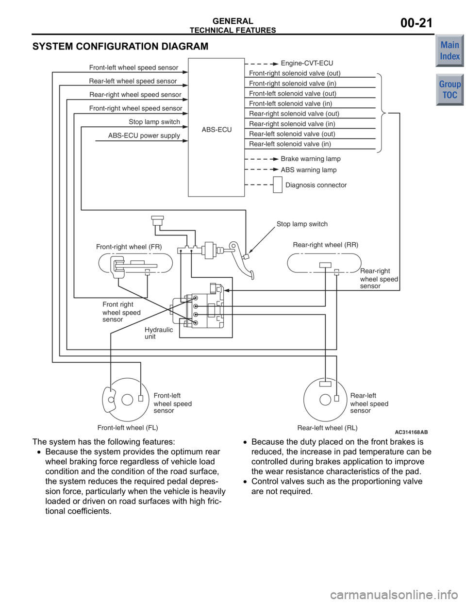
SYSTEM CONFIGURATION DIAGRAM
AC314168
Stop lamp switch
Front-right wheel speed sensor Rear-right wheel speed sensor
Rear-left wheel speed sensor Front-left wheel speed sensor
ABS-ECU power supply Engine-CVT-ECU
Front-right solenoid valve (out)
Front-right solenoid valve (in)
Front-left solenoid valve (out)
Front-left solenoid valve (in)
Rear-right solenoid valve (out)
Rear-right solenoid valve (in)
Rear-left solenoid valve (out)
Rear-left solenoid valve (in)
ABS-ECU
Hydraulic
unit Rear-right
wheel speed
sensor
Front right
wheel speed
sensor
Front-left
wheel speed
sensor Rear-left
wheel speed
sensor
Front-right wheel (FR)
Front-left wheel (FL) Rear-right wheel (RR)
Rear-left wheel (RL)
Stop lamp switch
AB
Brake warning lamp
ABS warning lamp
Diagnosis connector
The syst em has the following features:
•Because the system p rovides t he optimum rea r
wheel braking force regardless of vehicle load
co ndition a nd the condition of the road surface,
the system reduces the required pedal depre s
-
sion fo rce, particularly wh en th e veh icle is h eavily
lo aded o r driven on road surfaces with high fric
-
tional coef ficients.
•Because the duty place d on th e front brakes is
redu ced, th e increase in p ad tempe rature can be
controlled d uring brake s ap plication to impro ve
the we ar resist ance characteristics of the pad.
•Contro l valves such as the propo rtioning valve
are not required.
Page 207 of 364

TECHNICAL FEATURES
GENERAL00-22
ACTIVE STABILITY CONTROL SYSYEM
(ASC)
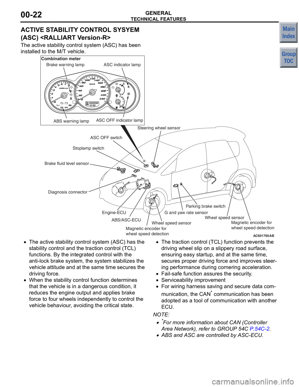
The active stability control system (ASC) has been
installed to the M/T vehicle.
AC601760AB
ABS warning lamp
Diagnosis connector Stoplamp switch
Steering wheel sensor
Wheel speed sensor Wheel speed sensor
G and yaw rate sensorParking brake switch
ASC OFF switch ASC indicator lamp
ASC OFF indicator lamp
Brake warning lamp
Combination meter
Brake fluid level sensor ABS/ASC-ECU
Engine-ECU
Magnetic encoder for
wheel speed detection Magnetic encoder for
wheel speed detection
•The
active st ability control syst em (ASC) has the
st ab ility control and t he traction control (TCL)
fun ctio ns. By the integra ted control with th e
ant i-lock b rake system, the system stabilizes th e
ve hicle attitu de and at the same time secures the
drivin g force.
•When the st ability control fun ction dete rmin es
tha t the vehicle is in a dangerou s condition, it
redu ces the e ngine outpu t and a pplies b rake
force to f our wheels indepe ndently to control th e
ve hicle be haviour, avoiding the critical state.
•The tract ion control (TCL) fun ction prevent s the
drivin g wheel slip on a slippery road sur face,
ensurin g easy st artup, an d at the same time,
secure s proper drivin g force and improves ste er
-
in g perfo rmance du ring cornering acce leration.
•Fail-safe functio n assures the security.
•Serviceability imp rovement
•For wiring h arness saving an d secure data com-
municatio n, the CAN* co mmunicatio n has been
ado pted a s a t ool o f commun ication with ano ther
ECU.
NO TE: .
•*For more informatio n about CAN (Con troller
Area Net wor k), refe r to GROUP 54C
P.54C-2.
•ABS and ASC are controlled by ASC-ECU.
Page 208 of 364

TECHNICAL FEATURES
GENERAL00-23
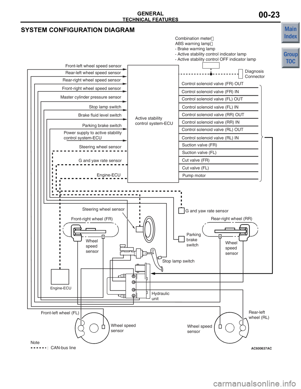
SYSTEM CONFIGURATION DIAGRAM
AC600637AC
Combination meter�
ABS warning lamp �
· Brake warning lamp
· Active stability control indicator lamp
· Active stability control OFF indicator lamp
Diagnosis
Connector
Control solenoid valve (FR) OUT
Control solenoid valve (FR) IN
Control solenoid valve (FL) OUT
Control solenoid valve (FL) IN
Control solenoid valve (RR) OUT
Control solenoid valve (RR) IN
Control solenoid valve (RL) OUT
Control solenoid valve (RL) IN Suction valve (FR)
Suction valve (FL)
Cut valve (FR)
Cut valve (FL) Pump motor
Active stability
control system-ECU
Front-left wheel speed sensor
Rear-left wheel speed sensor
Front-right wheel speed sensor Rear-right wheel speed sensor
Master cylinder pressure sensor Stop lamp switch
Parking brake switch
Brake fluid level switch
Power supply to active stability
control system-ECU Steering wheel sensor
G and yaw rate sensor
Engine-ECU
Steering wheel sensor
Front-right wheel (FR)
Wheel
speed
sensor
Engine-ECU
G and yaw rate sensor
Parking
brake
switch Rear-right wheel (RR)
Wheel
speed
sensor
Stop lamp switch
Hydraulic
unit Wheel speed
sensor Rear-left
wheel (RL)
Wheel speed
sensor
Front-left wheel (FL)
Note
: CAN-bus line
Page 211 of 364

TECHNICAL FEATURES
GENERAL00-26
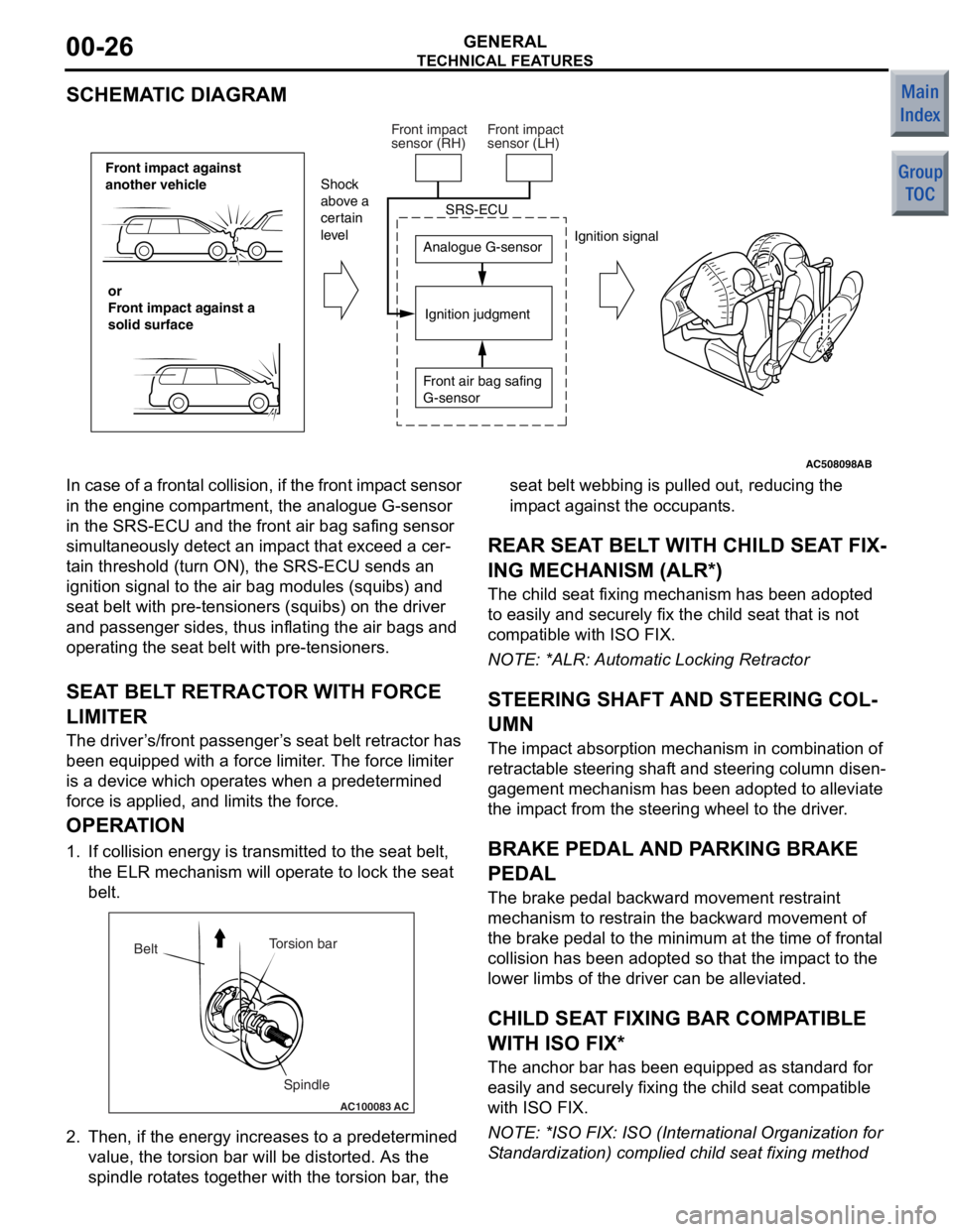
SCHEMATIC DIAGRAM
AC508098
Front impact against
another vehicleor
Front impact against a
solid surface Analogue G-sensor
Ignition judgment
Shock
above a
certain
level
Ignition signal
SRS-ECU
Front air bag safing
G-sensor
Front impact
sensor (RH)
Front impact
sensor (LH)
AB
In case of a
frontal collision, if the front imp act sensor
in the engine comp artment, the analogue G-sensor
in the SRS-ECU and t he front air bag safing sensor
simult aneously de tect an imp act th at excee d a cer
-
ta in threshold (turn ON), the SRS-ECU sen ds an
ignition signal to the air bag modules (squ ibs) and
seat belt with pre-te nsioners (squibs) on the driver
and p asseng er sides, thus inflating the air bag s and
operating the seat belt with pre -tensioner s.
SEAT BEL T RETRACT OR WITH FORCE
LIMITE R
The driver ’s /front p asseng er’s seat belt retractor has
been e quipped with a force limit er. The force limiter
is a device which operat es when a predetermined
force is applied, an d limits the for ce.
OPERA TION
1. If collision energy is transmit ted to the seat belt,
th e ELR mechanism will oper ate to lock the seat
be lt.
AC100083
Torsion bar
Spindle
Belt
AC
2.
Then, if the en ergy increase s to a prede termined
value , the to rsion bar will b e distorted . As th e
spind le rot ate s tog ether with the t orsion bar , the seat b
elt webb ing is p ulle d out, reducing th e
imp act against t he occupants.
REAR SEA T BELT WITH CHILD SEA T FIX-
ING MECHANISM (ALR*)
The child seat fixing mechanism h as b een ad opted
to easily and securely fix the child seat that is not
comp atible with ISO FIX.
NO TE: *ALR: Automatic Lockin g Retractor
STEERING SHAFT AND STEERING COL-
UMN
The impact ab sorption mech anism in combin ation of
retract able steerin g shaft and steering co lumn disen
-
gagement mecha nism has been ad opted t o alle viate
the imp act from th e steering wheel to the d rive r.
BRAKE PEDAL AND PA RKING BRAKE
PEDAL
The bra ke pe dal b ackward mo vement restraint
mechanism to restrain the backward movement of
the brake p edal to the minimum at the time o f f ront al
collision h as b een ad opted so that the impact to th e
lower limb s of the driver can be alleviated.
CHILD SEAT FIXING BAR COMP ATIBLE
WITH ISO FIX*
The an chor bar has been equipped a s st andard fo r
easily and secu rely fixing the child seat comp atible
with ISO FIX.
NO TE: *ISO F IX: ISO (In ternational Orga nization for
S tand ardizatio n) complied child se at fixing method
Page 215 of 364
VEHICLE IDENTIFICATION
GENERAL00-30
VEHICLE IDENTIFICATION
M2000001002264
MODELS
Model codePrice classEngine modelTransmission modelFuel supply
system
Z23AXNMHR8LS4A91 DOHC MIVEC
(1,499 mL)F5MGA (5-speed M/T, floor
shift) MPI
XNXHR8VR-X
XSMHR8LSF1C1A (INVECS-III CVT,
smart shift)
XSXHR8VR-X
Z27AXNGFR8RALLIART
Version-R4G15 DOHC MIVEC with
Intercooler Turbocharger
(1,468 mL ) F5MGB (5-speed M/T, floor
shift)
MODEL CODE
AC601074
1 23456789
AB
No.ItemConten t
1Develop mentZ2MITSUB ISHI COL T
2Engine type31, 499 mL petro l engine
(4A91)
71, 468 mL petro l engine
(4G15)
3SortAPassenger car
4Body styleX4-door hatchback
5Transmission
typeNFloor shift M/T
SSmart shift CVT
6Trim levelGRALLIART Version-R
MLS
XVR-X
7Specification
engine featureFDOHC-MPI-MIVEC with
Intercooler Turbocharger
HDOHC-MPI-MIVEC
8Steering wheel
locationRRight hand drive
9Destination8For Australia and New
Zealand
No. Item Content
Page 216 of 364
MAJOR SPECIFICATIONS
GENERAL00-31
MAJOR SPECIFICATIONS
M2000030000837
AC401657AB
1
2 34
658
97
ItemZ23A
XSMHR8XSXHR8
LSVR-X
Vehicle dimensions mmFront track11,460
Overall width21,680
Front overhang3790
Wheel base42,500
Rear overhang5595
Overall length63,885
Ground clearance
(unladen)7150
Overall height (unladen)81,550
Rear track91,445
Vehicle weight kgKerb weight1,0501,065
Max. gross vehicle weight1,490
Max. axle weight rating-front810
Max. axle weight rating-rear700
Seating capacity5
EngineModel code4A91
Total displacement mL1,499
TransmissionModel codeF1C1A
Ty p eSmart shift CVT
Fuel systemFuel supply systemMPI
Page 217 of 364
MAJOR SPECIFICATIONS
GENERAL00-32
M2000030000848
AC401657AB
1
2 34
658
97
ItemZ23AZ27A
XNMHR8XNXHR8XNGFR8
LSVR-XRALLIART Version-R
Vehicle dimensions
mmFront track11,4601,465
Overall width21,6801,695
Front overhang3790815
Wheel base42,500
Rear overhang5595610
Overall length63,8853,925
Ground clearance
(unladen)7150
Overall height (unladen)81,550
Rear track91,4451,450
Vehicle weight kgKerb weight1,0201,0351,130
Max. gross vehicle weight1,4601,470
Max. axle weight rating-front780850
Max. axle weight rating-rear700640
Seating capacity54
EngineModel code4A914G15 (with intercooler,
turbocharger)
Total displacement mL1,4991,468
TransmissionModel codeF5MGAF5MGB
Ty p eFloor shift M/T
Fuel systemFuel supply systemMPI