2006 MERCEDES-BENZ SPRINTER engine
[x] Cancel search: enginePage 2120 of 2305
(12) Install the plastic routing clip retainer onto
the A/C suction line.
(13) Reconnect the negative battery cable.
(14) Evacuate the refrigerant system (Refer to 24 -
HEATING & AIR CONDITIONING/PLUMBING -
STANDARD PROCEDURE - REFRIGERANT SYS-
TEM EVACUATE).
(15) Charge the refrigerant system (Refer to 24 -
HEATING & AIR CONDITIONING/PLUMBING -
STANDARD PROCEDURE - REFRIGERANT SYS-
TEM CHARGE).
WATER VALVE
REMOVAL
(1) Disconnect and isolate the negative battery
cable.
(2) Partially drain the engine cooling system
(Refer to 7 - COOLING/ENGINE/COOLANT - STAN-
DARD PROCEDURE - DRAINING COOLING SYS-
TEM).
(3) Disconnect the wire harness connector from the
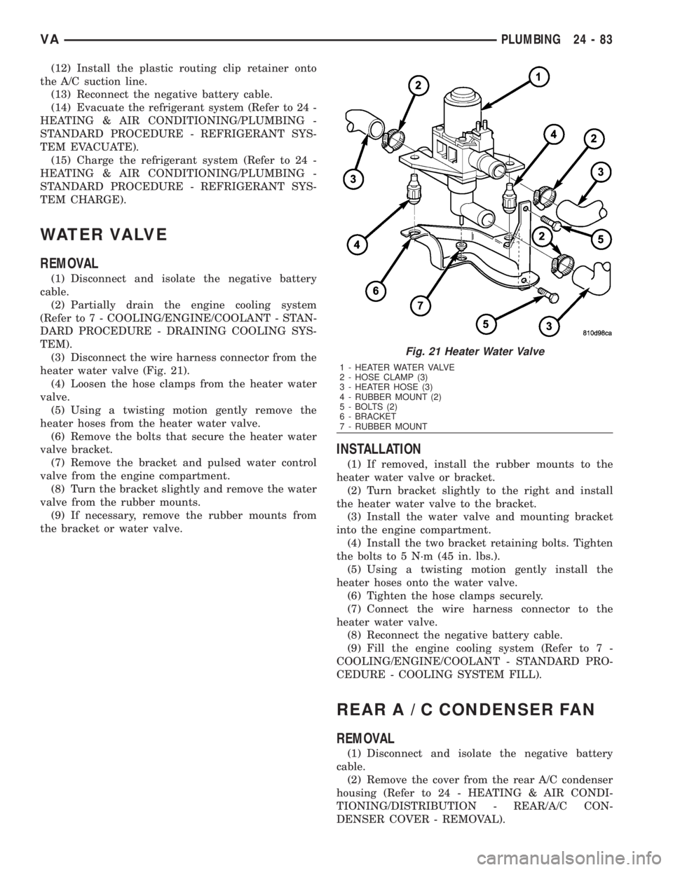
heater water valve (Fig. 21).
(4) Loosen the hose clamps from the heater water
valve.
(5) Using a twisting motion gently remove the
heater hoses from the heater water valve.
(6) Remove the bolts that secure the heater water
valve bracket.
(7) Remove the bracket and pulsed water control
valve from the engine compartment.
(8) Turn the bracket slightly and remove the water
valve from the rubber mounts.
(9) If necessary, remove the rubber mounts from
the bracket or water valve.
INSTALLATION
(1) If removed, install the rubber mounts to the
heater water valve or bracket.
(2) Turn bracket slightly to the right and install
the heater water valve to the bracket.
(3) Install the water valve and mounting bracket
into the engine compartment.
(4) Install the two bracket retaining bolts. Tighten
the bolts to 5 N´m (45 in. lbs.).
(5) Using a twisting motion gently install the
heater hoses onto the water valve.
(6) Tighten the hose clamps securely.
(7) Connect the wire harness connector to the
heater water valve.
(8) Reconnect the negative battery cable.
(9) Fill the engine cooling system (Refer to 7 -
COOLING/ENGINE/COOLANT - STANDARD PRO-
CEDURE - COOLING SYSTEM FILL).
REARA/CCONDENSER FAN
REMOVAL
(1) Disconnect and isolate the negative battery
cable.
(2) Remove the cover from the rear A/C condenser
housing (Refer to 24 - HEATING & AIR CONDI-
TIONING/DISTRIBUTION - REAR/A/C CON-
DENSER COVER - REMOVAL).
Fig. 21 Heater Water Valve
1 - HEATER WATER VALVE
2 - HOSE CLAMP (3)
3 - HEATER HOSE (3)
4 - RUBBER MOUNT (2)
5 - BOLTS (2)
6 - BRACKET
7 - RUBBER MOUNT
VAPLUMBING 24 - 83
Page 2141 of 2305
CABIN HEATER
TABLE OF CONTENTS
page page
CABIN HEATER
DESCRIPTION........................104
OPERATION..........................104
DIAGNOSIS AND TESTING
SUPPLEMENTAL CABIN HEATER........104
EXHAUST TUBE
REMOVAL............................105
INSTALLATION........................106
FUEL DOSING PUMP
DESCRIPTION........................106
OPERATION..........................106
REMOVAL............................106
INSTALLATION........................107
FUEL LINE
STANDARD PROCEDURE
CLEANING.........................107REMOVAL............................108
INSTALLATION........................109
HEATER UNIT
REMOVAL
HEATER UNIT.......................110
WIRE HARNESS.....................110
INSTALLATION
HEATER UNIT.......................110
WIRE HARNESS.....................111
INLET HOSE
REMOVAL............................111
INSTALLATION........................112
CABIN HEATER
DESCRIPTION
Vehicles equipped with the diesel engine are also
equipped with a supplemental cabin heater. This
cabin heater is mounted under the vehicle and oper-
ates similar to an oil fired furnace. The heater burns
small amounts of fuel to provide additional heat to
the coolant. Coolant is routed from the engine, to the
supplemental cabin heater and then to the front
heater core. This provides additional heat to the pas-
senger compartment. The supplemental cabin heater
system is interfaced to the vehicles on-board com-
puter systems and DRBIIItdiagnostics.
The supplemental cabin heater has an electronic
control module that monitors the heat output of the
heater. The cabin heater operates at full load (5 kW),
half load or idle mode (no additional heat) depending
on engine coolant temperature.
OPERATION
The supplemental cabin heater is activated by
using the temperature control on the A/C-heater con-
trol. The supplemental cabin heater is activated
when the temperature control is set to/or above the
upper set point. The supplemental cabin heater can
operate in a full or partial load range as well as an
idle mode, all dependent on the engine coolant tem-
perature. The heater unit will also turn off if the
temperature control is set to less than the lower set
point. The supplemental cabin heater can take up to
three minutes to completely shut down when eitherthe heater temperature is set below the lower set
point or the vehicle ignition is turned off.
The supplemental cabin heater only operates when
the engine is running, the mileage exceeds 8 kilome-
ter (5 mph) and the fuel tank volume exceeds 1/8 of a
tank. The heater should start if the coolant temper-
ature is below 40É C (104É F).
NOTE: Do not apply a strong vacuum directly on
the supplemental cabin heater exhaust line. Place
the vacuum within 75 mm (3 inches) of the exhaust
port. Too strong of a vacuum can prevent the heater
from starting. The heater control module monitors
the blower speed and combustion during its start-
up.
DIAGNOSIS AND TESTING
SUPPLEMENTAL CABIN HEATER
Refer to the Symptoms Diagnosis table for basic
checks of the diesel fueled supplemental cabin heater.
24 - 104 CABIN HEATERVA
Page 2147 of 2305
(7) With the DRBIIItscan tool in Cabin Heater,
select System Tests and Dosing Pump Prime. Allow
the dosing pump to run for the full 45 second cycle
time. When the 45 second cycle is complete, press
Page Back on the DRBIIItscan tool key pad to exit
the Dosing Pump Prime. The Dosing Pump Priming
procedure is now complete.
HEATER UNIT
REMOVAL
HEATER UNIT
WARNING: Do not operate the diesel supplemental
cabin heater in an enclosed area such as a garage
that does not have exhaust ventilation facilities.
Always vent the cabin heater exhaust when operat-
ing the cabin heater. Allow the diesel supplemental
cabin heater to cool before performing any service
procedures to the cabin heater. Verify that all diesel
supplemental cabin heater fuel lines are securely
fastened to their respective components before per-
forming any service procedures to the cabin heater.
Failure to follow these warnings may result in pos-
sible personal injury or death.
(1) Raise and support the vehicle. Take note of the
location of the flexible section of the cabin heater
exhaust tube.
(2) Drain the engine cooling system (Refer to 7 -
COOLING - STANDARD PROCEDURE - DRAINING
COOLING SYSTEM).
(3) Carefully open one hose to the underbody tube
assembly and drain the remaining coolant. A salvage
hose is a good idea to control the residual coolant, as
flow will occur from both the cabin heater and the
hose and tube assemblies.
(4) Remove the second hose from the underbody
hose and tube assembly.
(5) Loosen the hose and tube assembly from the
toe-board crossmember at two locations.
(6) Disconnect the electrical connector from the
body harness near the toe-board crossmember and
rail.
(7) Remove the wiring harness from the toe-board
crossmember (Refer to 24 - HEATING & AIR CON-
DITIONING/CABIN HEATER/HEATER UNIT -
REMOVAL - WIRE HARNESS).
(8) Open the fuel filler cap. Disconnect the rubber
fuel hose between the body tube assembly and the
fuel pump nipple at the body tube joint. A minimal
amount of fuel may flow from the open port.
NOTE: Utilize an approved fuel storage container to
catch any residual fuel.(9) Loosen the two fasteners at the rail. Take care
to notice that the exhaust tube bracket tab is on top
of the heater bracket and that there are two spacer
washers installed between the rubber grommets.
(10) Remove the flexible section of the cabin
heater exhaust tube from the exhaust tube by loos-
ening the clamp. Remove the hose from the exhaust
tube. Removal of the rail tube assembly may aid in
this service operation (Refer to 24 - HEATING & AIR
CONDITIONING/CABIN HEATER/EXHAUST TUBE
- REMOVAL).
(11) Remove seat hex nut at the heater mounting
flange to crossmember.
(12) Loosen the remaining fasteners which mount
the exhaust tube assembly to the vehicle.
(a) Install a suitable support device under the
cabin heater and secure the cabin heater to the
support.
(13) Loosen the remaining three fasteners to the
crossmembers.
(14) Remove the loosened fasteners that support
the cabin heater while supporting the weight of the
heater.
(15) Swing the cabin heater mounting bracket
from between the exhaust bracket and rail mounting
location. Drain any residual coolant from the cabin
heater.
(16) Remove the cabin heater from the vehicle.
WIRE HARNESS
(1) Raise and support the vehicle while taking note
of the location of the flexible exhaust tube section.
(2) Disconnect the cabin heater wire harness con-
nector from the vehicle wiring harness.
(3) Disconnect the cabin heater wire harness con-
nector from the dosing pump.
(4) Disconnect the two cabin heater wire harness
connectors from the cabin heater controller.
(5) Remove two wiring harness retainers from the
underbody.
(6) Remove two wiring harness retainers from the
cabin heater shield.
(7) Carefully route the cabin heater wire harness
out the left side between the heater unit and the
heater shield.
INSTALLATION
HEATER UNIT
(1) Install the cabin heater mounting bracket
between the exhaust bracket and the rail mounting
location.
(2) Support the cabin heater and install the fasten-
ers that secure the cabin heater to the mounting
bracket.
(3) Install the three fasteners to the crossmem-
bers. Tighten the M6 fasteners to 7 N´m (62 in. lbs.).
24 - 110 CABIN HEATERVA
Page 2148 of 2305
(4) Position the two spacer washers between the
body and the rubber grommets for the two mounting
points on the rail.
(5) Tighten the remaining M6 fasteners to 7 N´m
(62 in. lbs.) and the M8 fasteners to 23 N´m (17 ft.
lbs.) which mount the exhaust tube assembly to the
vehicle.
(6) Install the seat hex nut at the heater mounting
flange to the crossmembers. Tighten the nut to 60
N´m (44 ft. lbs.)
(7) Install the flexible section of the cabin heater
exhaust tube to the exhaust tube. Tighten the M6
bolt of the clamp securley. Install the hose to the
exhaust tube.
(8) Tighten the two M8 fasteners at the rail to 23
N´m (17 ft. lbs.). Taking care so that the exhaust
tube bracket tab is on the top of the heater bracket.
(9) Install the wiring harness (Refer to 24 - HEAT-
ING & AIR CONDITIONING/CABIN HEATER/
HEATER UNIT - INSTALLATION - WIRE
HARNESS).
(10) Tighten the hose and tube assembly to the
toe-board crossmember at two locations.
(11) Install the second hose to the underbody hose
and tube assembly.
(12) Connect the rubber fuel hose between the
body tube assembly and the fuel pump nipple at the
body tube joint. Close the fuel fill cap.
(13) Remove the cabin heater support device from
under the vehicle.
(14) Lower the vehicle.
(15) Fill the engine cooling system (Refer to 7 -
COOLING - STANDARD PROCEDURE - COOLING
SYSTEM FILL).
(16) Verify function of the heater unit.
WIRE HARNESS
(1) Carefully route the cabin heater wire harness
from the left side between the heater unit and the
heater shield.
(2) Install the two wiring harness retainers to the
cabin heater shield.
(3) Route the wiring harness along the underside
of the vehicle and install the two wiring harness
retainers to the underbody.
(4) Connect the two cabin heater wire harness con-
nectors to the cabin heater controller.
(5) Connect the cabin heater wire harness to the
dosing pump.
(6) Connect the cabin heater wire harness connec-
tor to the vehicle wiring harness.
(7) Lower the vehicle.
(8) Verify function of the heater unit.
INLET HOSE
REMOVAL
NOTE: The air intake tube for the supplemental
cabin heater is part of an assembly that includes
the heater cooling intake and return pipes. If the
cabin heater air intake tube requires removal or
replacement the entire cabin heater assembly will
require removal or replacement.
(1) Drain the engine cooling system (Refer to 7 -
COOLING - STANDARD PROCEDURE - DRAINING
COOLING STSTEM).
(2) Remove clamps from the cabin heater tubes at
the lower heater port and the lower EGR connector
which are located under the hood.
(3) Remove the retaining clamp at the cabin
heater air intake muffler connection (Refer to 24 -
HEATING & AIR CONDITIONING/CABIN HEAT-
ER/INLET MUFFLER - REMOVAL).
(4) Remove the clamp at the flexible tube to steel
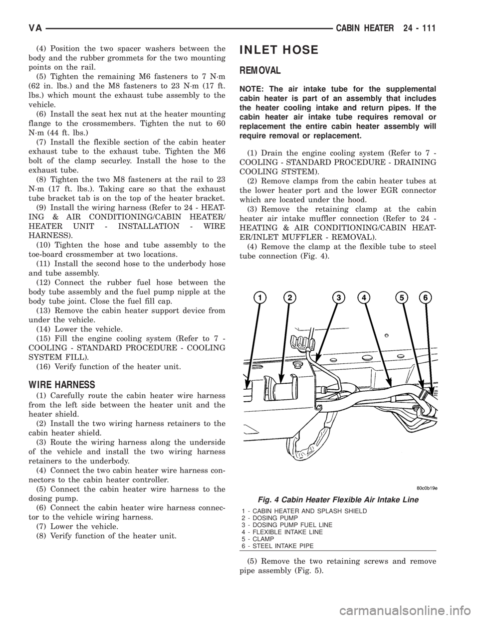
tube connection (Fig. 4).
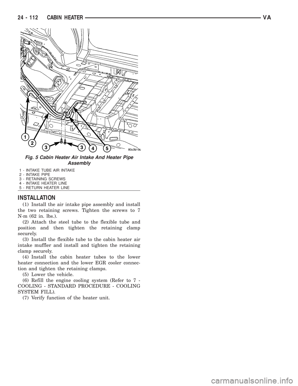
(5) Remove the two retaining screws and remove
pipe assembly (Fig. 5).
Fig. 4 Cabin Heater Flexible Air Intake Line
1 - CABIN HEATER AND SPLASH SHIELD
2 - DOSING PUMP
3 - DOSING PUMP FUEL LINE
4 - FLEXIBLE INTAKE LINE
5 - CLAMP
6 - STEEL INTAKE PIPE
VACABIN HEATER 24 - 111
Page 2149 of 2305
INSTALLATION
(1) Install the air intake pipe assembly and install
the two retaining screws. Tighten the screws to 7
N´m (62 in. lbs.).
(2) Attach the steel tube to the flexible tube and
position and then tighten the retaining clamp
securely.
(3) Install the flexible tube to the cabin heater air
intake muffler and install and tighten the retaining
clamp securely.
(4) Install the cabin heater tubes to the lower
heater connection and the lower EGR cooler connec-
tion and tighten the retaining clamps.
(5) Lower the vehicle.
(6) Refill the engine cooling system (Refer to 7 -
COOLING - STANDARD PROCEDURE - COOLING
SYSTEM FILL).
(7) Verify function of the heater unit.
Fig. 5 Cabin Heater Air Intake And Heater Pipe
Assembly
1 - INTAKE TUBE AIR INTAKE
2 - INTAKE PIPE
3 - RETAINING SCREWS
4 - INTAKE HEATER LINE
5 - RETURN HEATER LINE
24 - 112 CABIN HEATERVA
Page 2151 of 2305
(4) Connect the wiring harness connector to the
CCV heater (Fig. 1).
(5) Install the turbocharger heat shield.
(6) Connect the negative battery cable.
CRANKCASE VENTILATION
BREATHER
DESCRIPTION
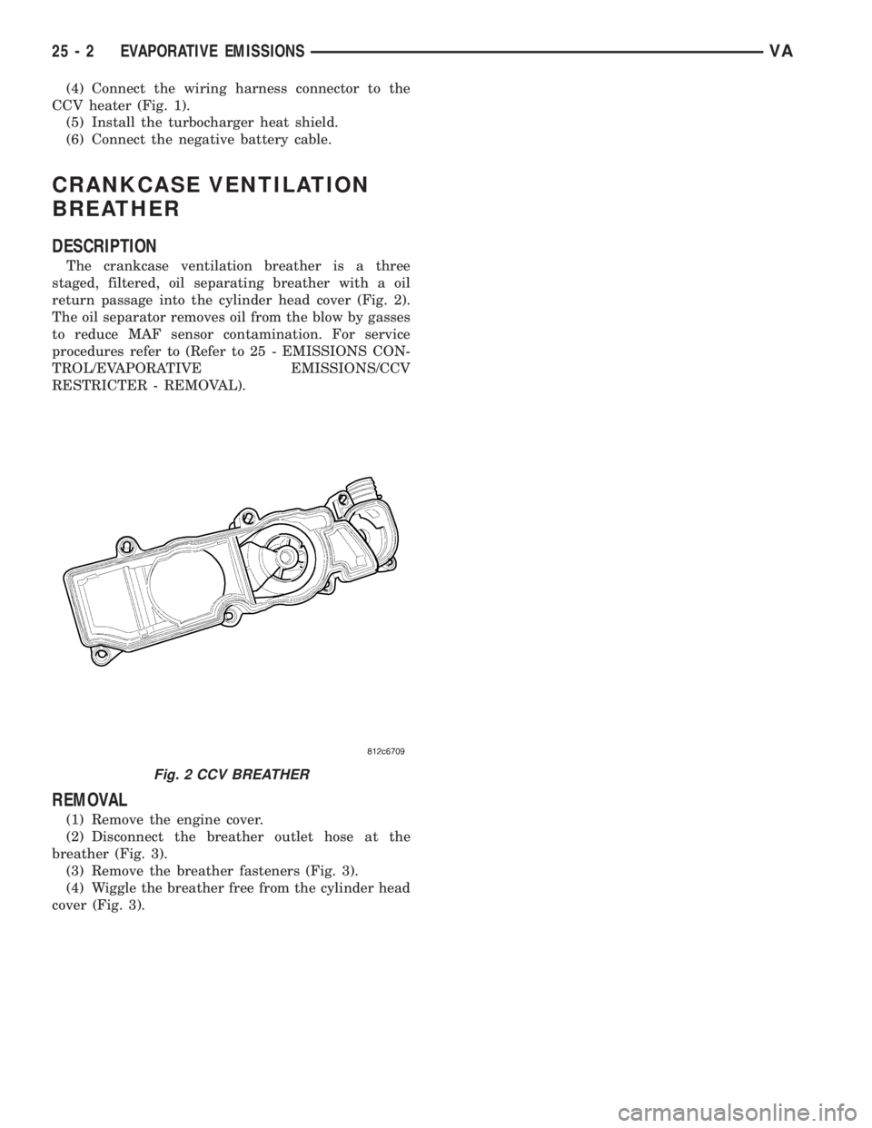
The crankcase ventilation breather is a three
staged, filtered, oil separating breather with a oil
return passage into the cylinder head cover (Fig. 2).
The oil separator removes oil from the blow by gasses
to reduce MAF sensor contamination. For service
procedures refer to (Refer to 25 - EMISSIONS CON-
TROL/EVAPORATIVE EMISSIONS/CCV
RESTRICTER - REMOVAL).
REMOVAL
(1) Remove the engine cover.
(2) Disconnect the breather outlet hose at the
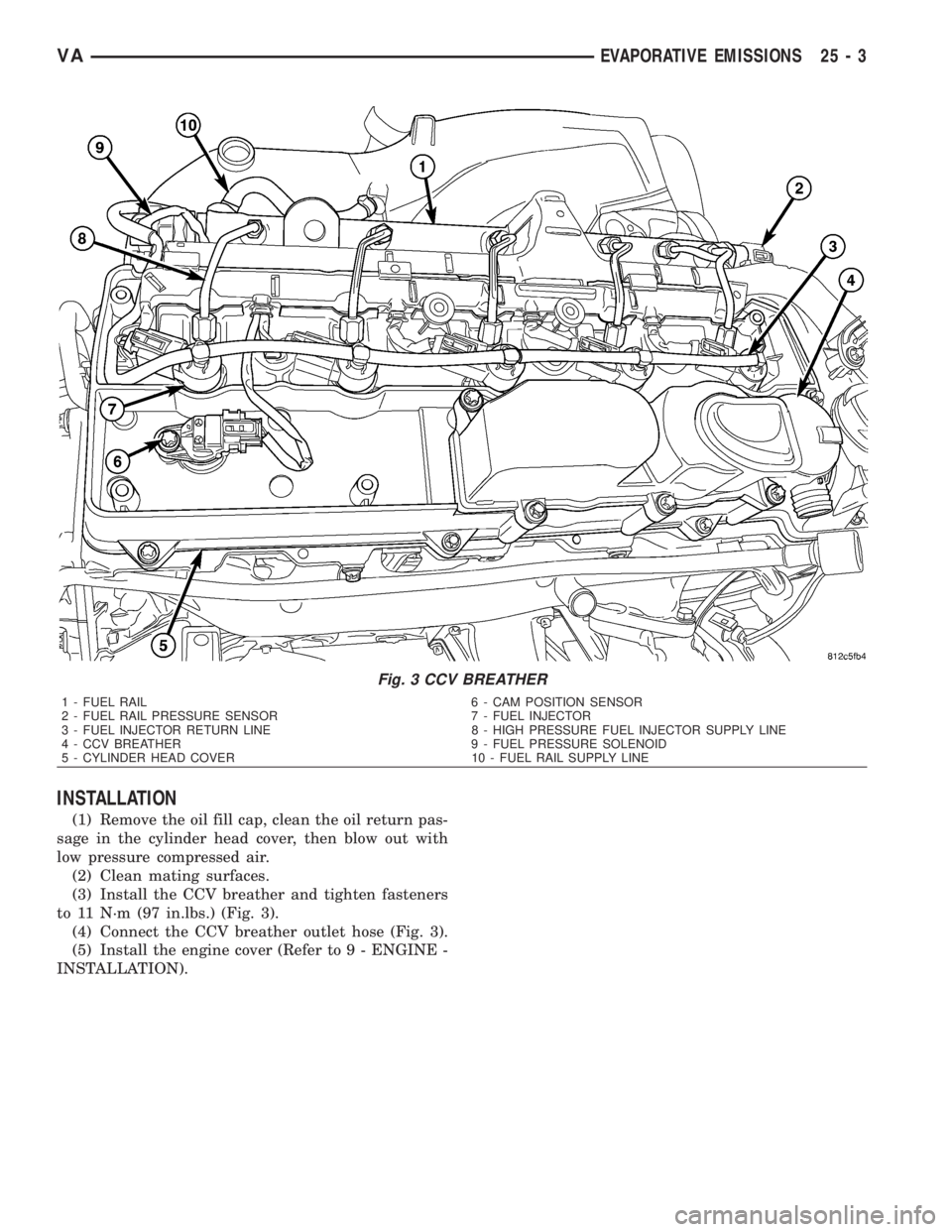
breather (Fig. 3).
(3) Remove the breather fasteners (Fig. 3).
(4) Wiggle the breather free from the cylinder head
cover (Fig. 3).
Fig. 2 CCV BREATHER
25 - 2 EVAPORATIVE EMISSIONSVA
Page 2152 of 2305
INSTALLATION
(1) Remove the oil fill cap, clean the oil return pas-
sage in the cylinder head cover, then blow out with
low pressure compressed air.
(2) Clean mating surfaces.
(3) Install the CCV breather and tighten fasteners
to 11 N´m (97 in.lbs.) (Fig. 3).
(4) Connect the CCV breather outlet hose (Fig. 3).
(5) Install the engine cover (Refer to 9 - ENGINE -
INSTALLATION).
Fig. 3 CCV BREATHER
1 - FUEL RAIL 6 - CAM POSITION SENSOR
2 - FUEL RAIL PRESSURE SENSOR 7 - FUEL INJECTOR
3 - FUEL INJECTOR RETURN LINE 8 - HIGH PRESSURE FUEL INJECTOR SUPPLY LINE
4 - CCV BREATHER 9 - FUEL PRESSURE SOLENOID
5 - CYLINDER HEAD COVER 10 - FUEL RAIL SUPPLY LINE
VAEVAPORATIVE EMISSIONS 25 - 3
Page 2153 of 2305
EXHAUST GAS RECIRCULATION
TABLE OF CONTENTS
page page
EXHAUST GAS RECIRCULATION
DESCRIPTION..........................4
VA LV E
DESCRIPTION..........................5
OPERATION............................6REMOVAL.............................6
INSTALLATION..........................6
VALVE COOLER
DESCRIPTION..........................6
EXHAUST GAS RECIRCULA-
TION
DESCRIPTION
The EGR system can provide up to 35% exhaust
gas recirculation. The EGR operates during all
engine speed and load conditions. At wide open throt-
tle, it provides a 5% recirculation rate. The EGR
shuts down during high engine idle to avoid carbon
build up on the valve. The EGR also deactivates if
the EGR temperature is too high. The EGR also has
a self cleaning function that opens and closes twice
after the engine has been shut off to eliminate soot
deposits.
Apart from the charge air distribution manifold
and the mixing chamber, the intake manifold also
includes a finned EGR cooler. Coolant flows through
the cooler to reduce the temperature of the recircu-
lated gas after it was cooled by running through the
cylinder head. The management of this temperature
significantly reduces emissions (Fig. 1).
25 - 4 EXHAUST GAS RECIRCULATIONVA