2006 MERCEDES-BENZ SPRINTER engine
[x] Cancel search: enginePage 2059 of 2305
NOTE: While holding the A/C-heater control in the
installation position, verify that the control cables
are not twisted.
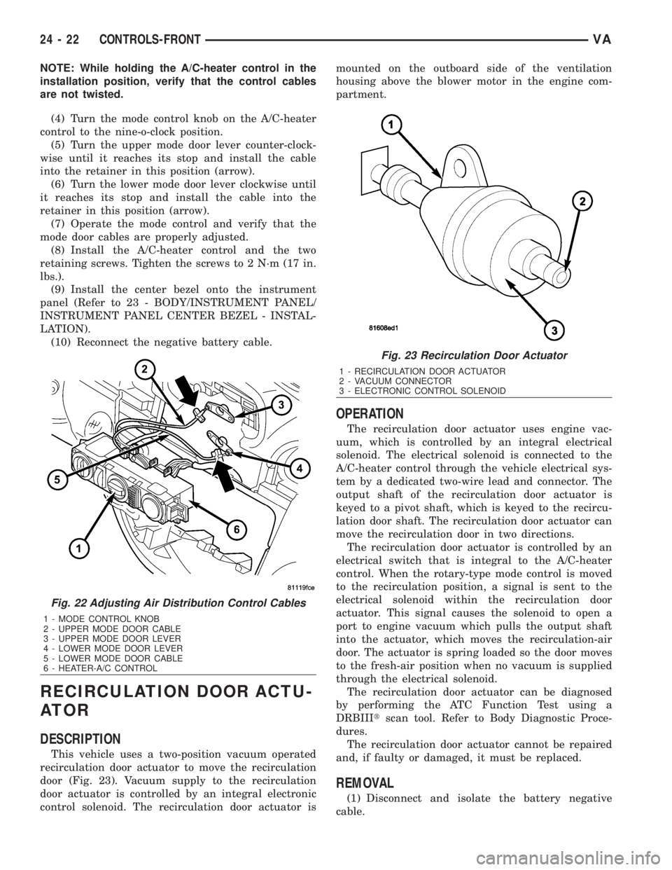
(4) Turn the mode control knob on the A/C-heater
control to the nine-o-clock position.
(5) Turn the upper mode door lever counter-clock-
wise until it reaches its stop and install the cable
into the retainer in this position (arrow).
(6) Turn the lower mode door lever clockwise until
it reaches its stop and install the cable into the
retainer in this position (arrow).
(7) Operate the mode control and verify that the
mode door cables are properly adjusted.
(8) Install the A/C-heater control and the two
retaining screws. Tighten the screws to 2 N´m (17 in.
lbs.).
(9) Install the center bezel onto the instrument
panel (Refer to 23 - BODY/INSTRUMENT PANEL/
INSTRUMENT PANEL CENTER BEZEL - INSTAL-
LATION).
(10) Reconnect the negative battery cable.
RECIRCULATION DOOR ACTU-
ATOR
DESCRIPTION
This vehicle uses a two-position vacuum operated
recirculation door actuator to move the recirculation
door (Fig. 23). Vacuum supply to the recirculation
door actuator is controlled by an integral electronic
control solenoid. The recirculation door actuator ismounted on the outboard side of the ventilation
housing above the blower motor in the engine com-
partment.
OPERATION
The recirculation door actuator uses engine vac-
uum, which is controlled by an integral electrical
solenoid. The electrical solenoid is connected to the
A/C-heater control through the vehicle electrical sys-
tem by a dedicated two-wire lead and connector. The
output shaft of the recirculation door actuator is
keyed to a pivot shaft, which is keyed to the recircu-
lation door shaft. The recirculation door actuator can
move the recirculation door in two directions.
The recirculation door actuator is controlled by an
electrical switch that is integral to the A/C-heater
control. When the rotary-type mode control is moved
to the recirculation position, a signal is sent to the
electrical solenoid within the recirculation door
actuator. This signal causes the solenoid to open a
port to engine vacuum which pulls the output shaft
into the actuator, which moves the recirculation-air
door. The actuator is spring loaded so the door moves
to the fresh-air position when no vacuum is supplied
through the electrical solenoid.
The recirculation door actuator can be diagnosed
by performing the ATC Function Test using a
DRBIIItscan tool. Refer to Body Diagnostic Proce-
dures.
The recirculation door actuator cannot be repaired
and, if faulty or damaged, it must be replaced.
REMOVAL
(1) Disconnect and isolate the battery negative
cable.
Fig. 22 Adjusting Air Distribution Control Cables
1 - MODE CONTROL KNOB
2 - UPPER MODE DOOR CABLE
3 - UPPER MODE DOOR LEVER
4 - LOWER MODE DOOR LEVER
5 - LOWER MODE DOOR CABLE
6 - HEATER-A/C CONTROL
Fig. 23 Recirculation Door Actuator
1 - RECIRCULATION DOOR ACTUATOR
2 - VACUUM CONNECTOR
3 - ELECTRONIC CONTROL SOLENOID
24 - 22 CONTROLS-FRONTVA
Page 2082 of 2305
DISTRIBUTION - FRONT
TABLE OF CONTENTS
page page
AIR FILTER
REMOVAL.............................45
INSTALLATION.........................45
AIR OUTLETS
REMOVAL.............................45
INSTALLATION.........................46
BLOWER MOTOR
REMOVAL.............................47
INSTALLATION.........................47
DEFROSTER DUCTS
REMOVAL.............................47
INSTALLATION.........................47FLOOR DISTRIBUTION DUCTS
REMOVAL.............................47
INSTALLATION.........................48
HVAC HOUSING
REMOVAL.............................48
DISASSEMBLY.........................49
ASSEMBLY............................50
INSTALLATION.........................50
INSTRUMENT PANEL DUCTS
REMOVAL.............................51
INSTALLATION.........................51
AIR FILTER
REMOVAL
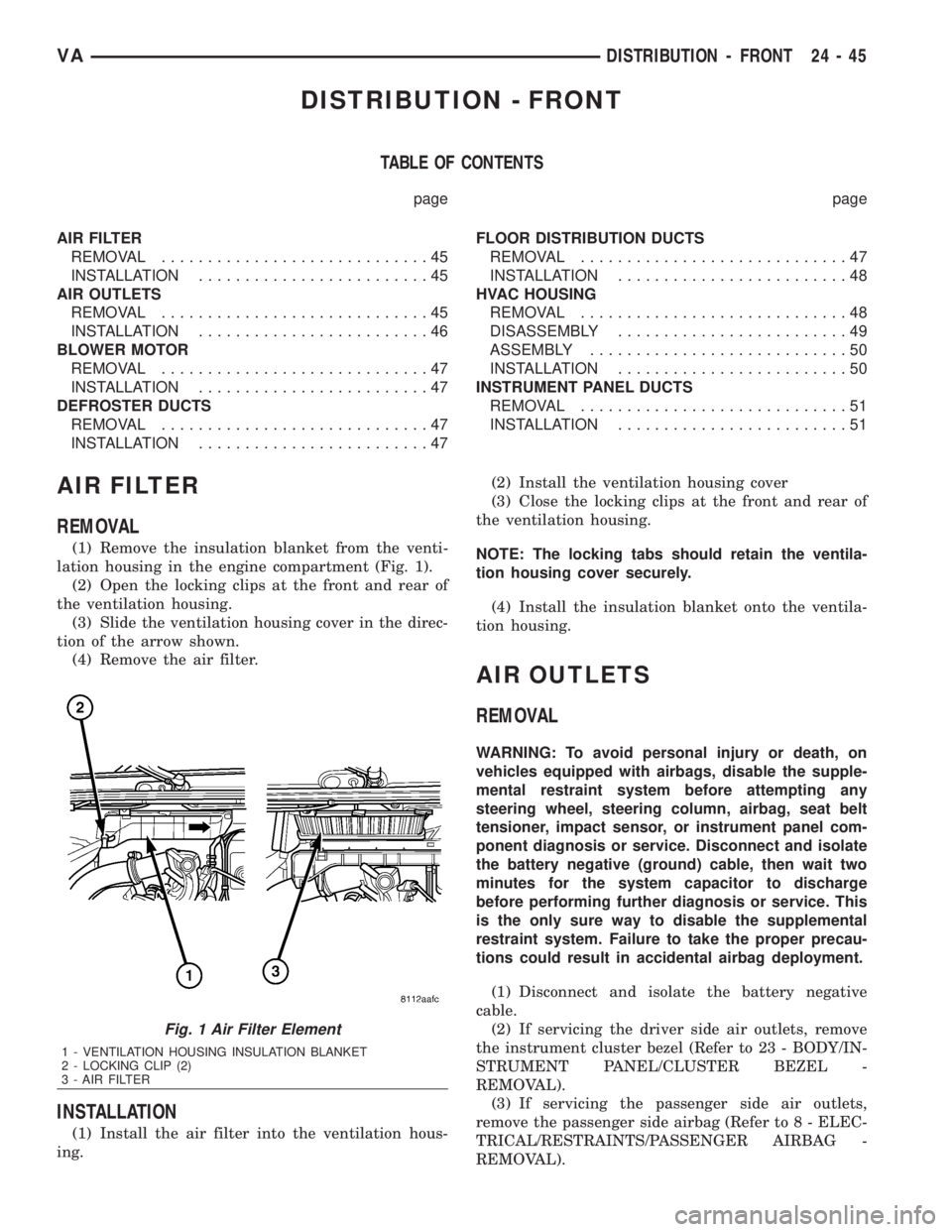
(1) Remove the insulation blanket from the venti-
lation housing in the engine compartment (Fig. 1).
(2) Open the locking clips at the front and rear of
the ventilation housing.
(3) Slide the ventilation housing cover in the direc-
tion of the arrow shown.
(4) Remove the air filter.
INSTALLATION
(1) Install the air filter into the ventilation hous-
ing.(2) Install the ventilation housing cover
(3) Close the locking clips at the front and rear of
the ventilation housing.
NOTE: The locking tabs should retain the ventila-
tion housing cover securely.
(4) Install the insulation blanket onto the ventila-
tion housing.
AIR OUTLETS
REMOVAL
WARNING: To avoid personal injury or death, on
vehicles equipped with airbags, disable the supple-
mental restraint system before attempting any
steering wheel, steering column, airbag, seat belt
tensioner, impact sensor, or instrument panel com-
ponent diagnosis or service. Disconnect and isolate
the battery negative (ground) cable, then wait two
minutes for the system capacitor to discharge
before performing further diagnosis or service. This
is the only sure way to disable the supplemental
restraint system. Failure to take the proper precau-
tions could result in accidental airbag deployment.
(1) Disconnect and isolate the battery negative
cable.
(2) If servicing the driver side air outlets, remove
the instrument cluster bezel (Refer to 23 - BODY/IN-
STRUMENT PANEL/CLUSTER BEZEL -
REMOVAL).
(3) If servicing the passenger side air outlets,
remove the passenger side airbag (Refer to 8 - ELEC-
TRICAL/RESTRAINTS/PASSENGER AIRBAG -
REMOVAL).
Fig. 1 Air Filter Element
1 - VENTILATION HOUSING INSULATION BLANKET
2 - LOCKING CLIP (2)
3 - AIR FILTER
VADISTRIBUTION - FRONT 24 - 45
Page 2084 of 2305
BLOWER MOTOR
REMOVAL
(1) Disconnect and isolate the negative battery
cable.
(2) Remove the engine air cleaner housing cover
(Refer to 9 - ENGINE/AIR INTAKE SYSTEM/AIR
CLEANER ELEMENT - REMOVAL).
(3) Position the ventilation housing insulation
blanket out of the way of the blower motor assembly.
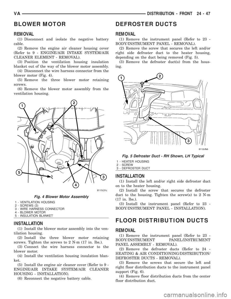
(4) Disconnect the wire harness connector from the
blower motor (Fig. 4).
(5) Remove the three blower motor retaining
screws.
(6) Remove the blower motor assembly from the
ventilation housing.
INSTALLATION
(1) Install the blower motor assembly into the ven-
tilation housing.
(2) Install the three blower motor retaining
screws. Tighten the screws to 2 N´m (17 in. lbs.).
(3) Connect the wire harness connector to the
blower motor.
(4) Install the ventilation housing insulation blan-
ket.
(5) Install the engine air cleaner cover (Refer to 9 -
ENGINE/AIR INTAKE SYSTEM/AIR CLEANER
HOUSING - INSTALLATION).
(6) Reconnect the negative battery cable.
DEFROSTER DUCTS
REMOVAL
(1) Remove the instrument panel (Refer to 23 -
BODY/INSTRUMENT PANEL - REMOVAL).
(2) Remove the screw that secures the left and/or
right side defroster duct to the heater housing,
depending on the duct being removed (Fig. 5).
(3) Remove the defroster duct(s) from the hous-
ing.
INSTALLATION
(1) Install the left and/or right side defroster duct
on to the heater housing.
(2) Install the screw that secures the defroster
duct to the housing. Tighten the screw(s) to 2 N´m
(17 in. lbs.).
(3) Install the instrument panel (Refer to 23 -
BODY/INSTRUMENT PANEL - INSTALLATION).
FLOOR DISTRIBUTION DUCTS
REMOVAL
(1) Remove the instrument panel (Refer to 23 -
BODY/INSTRUMENT PANEL/INSTRUMENT
PANEL ASSEMBLY - REMOVAL).
(2) Remove the defroster ducts (Refer to 24 -
HEATING & AIR CONDITIONING/DISTRIBUTION/
DEFROSTER DUCTS - REMOVAL).
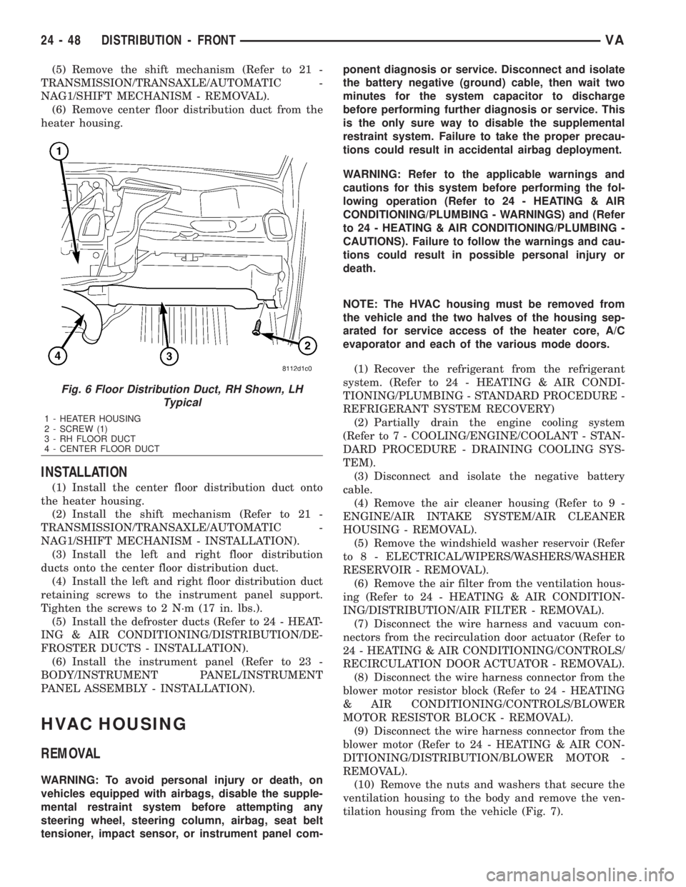
(3) Remove the screws that secure the left and
right floor distribution ducts to the instrument panel
support (Fig. 6).
(4) Remove floor distribution ducts from the center
floor distribution duct.
Fig. 4 Blower Motor Assembly
1 - VENTILATION HOUSING
2 - SCREWS (3)
3 - WIRE HARNESS CONNECTOR
4 - BLOWER MOTOR
5 - INSULATION BLANKET
Fig. 5 Defroster Duct - RH Shown, LH Typical
1 - HEATER HOUSING
2 - SCREW
3 - DEFROSTER DUCT
VADISTRIBUTION - FRONT 24 - 47
Page 2085 of 2305
(5) Remove the shift mechanism (Refer to 21 -
TRANSMISSION/TRANSAXLE/AUTOMATIC -
NAG1/SHIFT MECHANISM - REMOVAL).
(6) Remove center floor distribution duct from the
heater housing.
INSTALLATION
(1) Install the center floor distribution duct onto
the heater housing.
(2) Install the shift mechanism (Refer to 21 -
TRANSMISSION/TRANSAXLE/AUTOMATIC -
NAG1/SHIFT MECHANISM - INSTALLATION).
(3) Install the left and right floor distribution
ducts onto the center floor distribution duct.
(4) Install the left and right floor distribution duct
retaining screws to the instrument panel support.
Tighten the screws to 2 N´m (17 in. lbs.).
(5) Install the defroster ducts (Refer to 24 - HEAT-
ING & AIR CONDITIONING/DISTRIBUTION/DE-
FROSTER DUCTS - INSTALLATION).
(6) Install the instrument panel (Refer to 23 -
BODY/INSTRUMENT PANEL/INSTRUMENT
PANEL ASSEMBLY - INSTALLATION).
HVAC HOUSING
REMOVAL
WARNING: To avoid personal injury or death, on
vehicles equipped with airbags, disable the supple-
mental restraint system before attempting any
steering wheel, steering column, airbag, seat belt
tensioner, impact sensor, or instrument panel com-ponent diagnosis or service. Disconnect and isolate
the battery negative (ground) cable, then wait two
minutes for the system capacitor to discharge
before performing further diagnosis or service. This
is the only sure way to disable the supplemental
restraint system. Failure to take the proper precau-
tions could result in accidental airbag deployment.
WARNING: Refer to the applicable warnings and
cautions for this system before performing the fol-
lowing operation (Refer to 24 - HEATING & AIR
CONDITIONING/PLUMBING - WARNINGS) and (Refer
to 24 - HEATING & AIR CONDITIONING/PLUMBING -
CAUTIONS). Failure to follow the warnings and cau-
tions could result in possible personal injury or
death.
NOTE: The HVAC housing must be removed from
the vehicle and the two halves of the housing sep-
arated for service access of the heater core, A/C
evaporator and each of the various mode doors.
(1) Recover the refrigerant from the refrigerant
system. (Refer to 24 - HEATING & AIR CONDI-
TIONING/PLUMBING - STANDARD PROCEDURE -
REFRIGERANT SYSTEM RECOVERY)
(2) Partially drain the engine cooling system
(Refer to 7 - COOLING/ENGINE/COOLANT - STAN-
DARD PROCEDURE - DRAINING COOLING SYS-
TEM).
(3) Disconnect and isolate the negative battery
cable.
(4) Remove the air cleaner housing (Refer to 9 -
ENGINE/AIR INTAKE SYSTEM/AIR CLEANER
HOUSING - REMOVAL).
(5) Remove the windshield washer reservoir (Refer
to 8 - ELECTRICAL/WIPERS/WASHERS/WASHER
RESERVOIR - REMOVAL).
(6) Remove the air filter from the ventilation hous-
ing (Refer to 24 - HEATING & AIR CONDITION-
ING/DISTRIBUTION/AIR FILTER - REMOVAL).
(7) Disconnect the wire harness and vacuum con-
nectors from the recirculation door actuator (Refer to
24 - HEATING & AIR CONDITIONING/CONTROLS/
RECIRCULATION DOOR ACTUATOR - REMOVAL).
(8) Disconnect the wire harness connector from the
blower motor resistor block (Refer to 24 - HEATING
& AIR CONDITIONING/CONTROLS/BLOWER
MOTOR RESISTOR BLOCK - REMOVAL).
(9) Disconnect the wire harness connector from the
blower motor (Refer to 24 - HEATING & AIR CON-
DITIONING/DISTRIBUTION/BLOWER MOTOR -
REMOVAL).
(10) Remove the nuts and washers that secure the
ventilation housing to the body and remove the ven-
tilation housing from the vehicle (Fig. 7).
Fig. 6 Floor Distribution Duct, RH Shown, LH
Typical
1 - HEATER HOUSING
2 - SCREW (1)
3 - RH FLOOR DUCT
4 - CENTER FLOOR DUCT
24 - 48 DISTRIBUTION - FRONTVA
Page 2087 of 2305
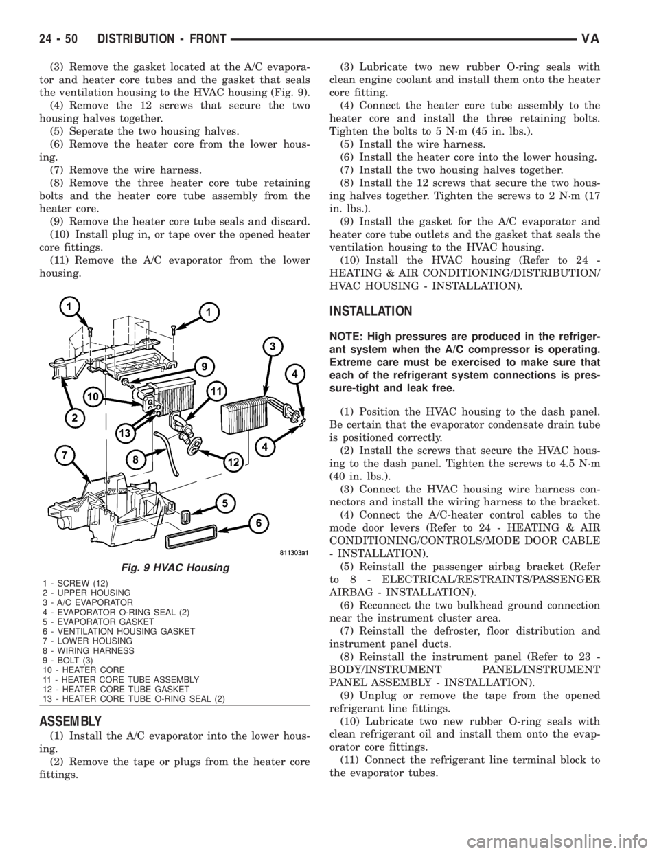
(3) Remove the gasket located at the A/C evapora-
tor and heater core tubes and the gasket that seals
the ventilation housing to the HVAC housing (Fig. 9).
(4) Remove the 12 screws that secure the two
housing halves together.
(5) Seperate the two housing halves.
(6) Remove the heater core from the lower hous-
ing.
(7) Remove the wire harness.
(8) Remove the three heater core tube retaining
bolts and the heater core tube assembly from the
heater core.
(9) Remove the heater core tube seals and discard.
(10) Install plug in, or tape over the opened heater
core fittings.
(11) Remove the A/C evaporator from the lower
housing.
ASSEMBLY
(1) Install the A/C evaporator into the lower hous-
ing.
(2) Remove the tape or plugs from the heater core
fittings.(3) Lubricate two new rubber O-ring seals with
clean engine coolant and install them onto the heater
core fitting.
(4) Connect the heater core tube assembly to the
heater core and install the three retaining bolts.
Tighten the bolts to 5 N´m (45 in. lbs.).
(5) Install the wire harness.
(6) Install the heater core into the lower housing.
(7) Install the two housing halves together.
(8) Install the 12 screws that secure the two hous-
ing halves together. Tighten the screws to 2 N´m (17
in. lbs.).
(9) Install the gasket for the A/C evaporator and
heater core tube outlets and the gasket that seals the
ventilation housing to the HVAC housing.
(10) Install the HVAC housing (Refer to 24 -
HEATING & AIR CONDITIONING/DISTRIBUTION/
HVAC HOUSING - INSTALLATION).
INSTALLATION
NOTE: High pressures are produced in the refriger-
ant system when the A/C compressor is operating.
Extreme care must be exercised to make sure that
each of the refrigerant system connections is pres-
sure-tight and leak free.
(1) Position the HVAC housing to the dash panel.
Be certain that the evaporator condensate drain tube
is positioned correctly.
(2) Install the screws that secure the HVAC hous-
ing to the dash panel. Tighten the screws to 4.5 N´m
(40 in. lbs.).
(3) Connect the HVAC housing wire harness con-
nectors and install the wiring harness to the bracket.
(4) Connect the A/C-heater control cables to the
mode door levers (Refer to 24 - HEATING & AIR
CONDITIONING/CONTROLS/MODE DOOR CABLE
- INSTALLATION).
(5) Reinstall the passenger airbag bracket (Refer
to 8 - ELECTRICAL/RESTRAINTS/PASSENGER
AIRBAG - INSTALLATION).
(6) Reconnect the two bulkhead ground connection
near the instrument cluster area.
(7) Reinstall the defroster, floor distribution and
instrument panel ducts.
(8) Reinstall the instrument panel (Refer to 23 -
BODY/INSTRUMENT PANEL/INSTRUMENT
PANEL ASSEMBLY - INSTALLATION).
(9) Unplug or remove the tape from the opened
refrigerant line fittings.
(10) Lubricate two new rubber O-ring seals with
clean refrigerant oil and install them onto the evap-
orator core fittings.
(11) Connect the refrigerant line terminal block to
the evaporator tubes.
Fig. 9 HVAC Housing
1 - SCREW (12)
2 - UPPER HOUSING
3 - A/C EVAPORATOR
4 - EVAPORATOR O-RING SEAL (2)
5 - EVAPORATOR GASKET
6 - VENTILATION HOUSING GASKET
7 - LOWER HOUSING
8 - WIRING HARNESS
9 - BOLT (3)
10 - HEATER CORE
11 - HEATER CORE TUBE ASSEMBLY
12 - HEATER CORE TUBE GASKET
13 - HEATER CORE TUBE O-RING SEAL (2)
24 - 50 DISTRIBUTION - FRONTVA
Page 2088 of 2305
(12) Install the two bolts that secure the refriger-
ant line terminal block to the A/C evaporator.
Tighten the bolts to 5 N´m (45 in. lbs.).
(13) Unplug or remove the tape from the heater
core hoses and tubes.
(14) Connect the heater hoses to the heater core
tubes and install the heater hose clamps.
(15) Install the ventilation housing to the dash
panel.
(16) Install the nuts and washers that secure the
ventilation housing to the dash panel. Tighten the
nuts to 5 N´m (45 in. lbs.).
(17) Connect the wire harness connectors to the
blower motor, blower motor resistor block and the
recirculation door actuator.
(18) Connect the vacuum harness connector to the
recirculation door actuator.
(19) Install the air filter into the ventilation hous-
ing (Refer to 24 - HEATING & AIR CONDITION-
ING/DISTRIBUTION/AIR FILTER -
INSTALLATION).
(20) Install the windshield washer reservoir (Refer
to 8 - ELECTRICAL/WIPERS/WASHERS/WASHER
RESERVOIR - INSTALLATION).
(21) Install the air cleaner housing (Refer to 9 -
ENGINE/AIR INTAKE SYSTEM/AIR CLEANER
HOUSING - INSTALLATION).
(22) Reconnect the negative battery cable.
(23) If the heater core is being replaced, flush the
cooling system (Refer to 7 - COOLING - STANDARD
PROCEDURE - COOLING SYSTEM CLEANING/
REVERSE FLUSHING).
(24) Refill the engine cooling system (Refer to 7 -
COOLING/ENGINE/COOLANT - STANDARD PRO-
CEDURE - COOLANT SYSTEM FILL).
(25) Evacuate the refrigerant system (Refer to 24 -
HEATING & AIR CONDITIONING/PLUMBING -
STANDARD PROCEDURE - REFRIGERANT SYS-
TEM EVACUATE).
(26) Charge the refrigerant system (Refer to 24 -
HEATING & AIR CONDITIONING/PLUMBING -
STANDARD PROCEDURE - REFRIGERANT SYS-
TEM CHARGE).
INSTRUMENT PANEL DUCTS
REMOVAL
(1) Remove the instrument panel (Refer to 23 -
BODY/INSTRUMENT PANEL/INSTRUMENT
PANEL ASSEMBLY - REMOVAL).
(2) Remove the defroster ducts (Refer to 24 -
HEATING & AIR CONDITIONING/DISTRIBUTION/
DEFROSTER DUCTS - REMOVAL).
(3) Remove the floor distribution ducts (Refer to 24
- HEATING & AIR CONDITIONING/DISTRIBU-
TION/FLOOR DISTRIBUTION DUCTS -
REMOVAL).(4) If removing the right instrument panel duct,
remove the passenger air bag module and bracket
(Refer to 8 - ELECTRICAL/RESTRAINTS/PASSEN-
GER AIRBAG - REMOVAL).
(5) Remove the screws that secure the left and/or
right instrument panel duct and remove the duct(s)
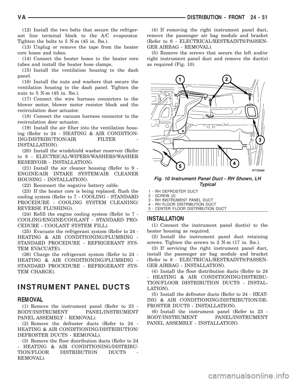
as required (Fig. 10).
INSTALLATION
(1) Connect the instrument panel duct(s) to the
heater housing as required.
(2) Install the instrument panel duct retaining
screws. Tighten the screws to 2 N´m (17 in. lbs.).
(3) If servicing the right instrument panel duct,
install the passenger air bag module and bracket
(Refer to 8 - ELECTRICAL/RESTRAINTS/PASSEN-
GER AIRBAG - INSTALLATION).
(4) Install the floor distribution ducts (Refer to 24
- HEATING & AIR CONDITIONING/DISTRIBU-
TION/FLOOR DISTRIBUTION DUCTS - INSTAL-
LATION).
(5) Install the defroster ducts (Refer to 24 - HEAT-
ING & AIR CONDITIONING/DISTRIBUTION/DE-
FROSTER DUCTS - INSTALLATION).
(6) Install the instrument panel (Refer to 23 -
BODY/INSTRUMENT PANEL/INSTRUMENT
PANEL ASSEMBLY - INSTALLATION).
Fig. 10 Instrument Panel Duct - RH Shown, LH
Typical
1 - RH DEFROSTER DUCT
2 - SCREW (2)
3 - RH INSTRUMENT PANEL DUCT
4 - RH FLOOR DISTRIBUTION DUCT
5 - CENTER FLOOR DISTRIBUTION DUCT
VADISTRIBUTION - FRONT 24 - 51
Page 2098 of 2305
REAR REFRIGERANT RESERVOIR
REMOVAL.............................95
INSTALLATION.........................95
REAR SUCTION LINE
DESCRIPTION.........................96
REMOVAL.............................96
INSTALLATION.........................98
REFRIGERANT LINE COUPLER
DESCRIPTION.........................98OPERATION...........................98
REMOVAL.............................99
INSTALLATION.........................99
UNDERBODY LINES
REMOVAL............................100
INSTALLATION........................102
PLUMBING
DESCRIPTION
The refrigerant lines and hoses are used to carry
the refrigerant between the various air conditioning
system components. A barrier hose design with a
nylon tube, which is sandwiched between rubber lay-
ers, is used for the R-134a air conditioning system on
this vehicle. This nylon tube helps to further contain
the R-134a refrigerant, which has a smaller molecu-
lar structure than R-12 refrigerant. The ends of the
refrigerant hoses are made from lightweight alumi-
num or steel, and commonly use braze-less fittings.
Any kinks or sharp bends in the refrigerant plumb-
ing will reduce the capacity of the entire air condi-
tioning system. Kinks and sharp bends reduce the
flow of refrigerant in the system. A good rule for the
flexible hose refrigerant lines is to keep the radius of
all bends at least ten times the diameter of the hose.
In addition, the flexible hose refrigerant lines should
be routed so they are at least 80 millimeters (3
inches) from the exhaust manifold.
OPERATION
High pressures are produced in the refrigerant sys-
tem when the air conditioning compressor is operat-
ing. Extreme care must be exercised to make sure
that each of the refrigerant system connections is
pressure-tight and leak free. It is a good practice to
inspect all flexible hose refrigerant lines at least once
a year to make sure they are in good condition and
properly routed.
The refrigerant lines and hoses cannot be repaired
and, if faulty or damaged, they must be replaced.
WARNINGS
WARNING: The A/C system contains refrigerant
under high pressure. Repairs should only be per-
formed by qualified service personnel. Severe per-
sonal injury or death may result from improper
service procedures.
WARNING: Avoid breathing the refrigerant and
refrigerant oil vapor or mist. Exposure may irritate
the eyes, nose, and/or throat. Wear eye protectionwhen servicing the A/C refrigerant system. Serious
eye injury can result from direct contact with the
refrigerant. If eye contact occurs, seek medical
attention immediately.
WARNING: Do not expose the refrigerant to open
flame. Poisonous gas is created when refrigerant is
burned. An electronic leak detector is recom-
mended. Severe personal injury or death may result
from improper service procedures.
WARNING: If accidental system discharge occurs,
ventilate the work area before resuming service.
Large amounts of refrigerant released in a closed
work area will displace the oxygen and cause suf-
focation and death.
WARNING: The evaporation rate of R-134a refriger-
ant at average temperature and altitude is extremely
high. As a result, anything that comes in contact
with the refrigerant will freeze. Always protect the
skin or delicate objects from direct contact with the
refrigerant.
WARNING: The R-134a service equipment or the
vehicle refrigerant system should not be pressure
tested or leak tested with compressed air. Some
mixtures of air and R-134a have been shown to be
combustible at elevated pressures. These mixtures
are potentially dangerous, and may result in fire or
explosion causing property damage, personal injury
or death.
WARNING: The engine cooling system is designed
to develop internal pressures of 97 to 123 kilopas-
cals (14 to 18 pounds per square inch). Do not
remove or loosen the coolant pressure cap, cylin-
der block drain plugs, radiator drain, radiator
hoses, heater hoses, or hose clamps while the
engine cooling system is hot and under pressure.
Allow the vehicle to cool for a minimum of 15 min-
utes before opening the cooling system for service.
Failure to observe this warning can result in seri-
ous burns from the heated engine coolant.
VAPLUMBING 24 - 61
Page 2100 of 2305
SYSTEM EMPTY
(1) Evacuate the refrigerant system to the lowest
degree of vacuum possible (approximately 28 in Hg.)
(Refer to 24 - HEATING & AIR CONDITIONING/
PLUMBING - STANDARD PROCEDURE - REFRIG-
ERANT SYSTEM EVACUATE). Determine if the
system holds a vacuum for 15 minutes. If vacuum is
held, a leak is probably not present. If system will
not maintain vacuum level, proceed to Step 2.
(2) Prepare and dispense 0.284 kilograms (10
ounces) of R-134a refrigerant into the evacuated
refrigerant system (Refer to 24 - HEATING & AIR
CONDITIONING/PLUMBING - STANDARD PRO-
CEDURE - REFRIGERANT SYSTEM CHARGE) and
proceed to Step 1 of the System Low procedure.
SYSTEM LOW
(1) Position the vehicle in a wind free work area.
This will aid in detecting small leaks.
(2) Operate the heating-A/C system with the
engine at idle under the following conditions for at
least five minutes.
²Doors or windows open
²Transmission in Park
²A/C-heater controls set to outside air, full cool,
panel mode, high blower and with A/C compressor
engaged
CAUTION: A leak detector only designed for R-12
refrigerant will not detect leaks in a R-134a refriger-
ant system.
(3) Shut the vehicle Off and wait 2-7 minutes.
Then use an electronic leak detector that is designed
to detect R-134a refrigerant and search for leaks. Fit-
tings, lines or components that appear to be oily usu-
ally indicate a refrigerant leak. To inspect the A/C
evaporator for leaks, insert the leak detector probe
into the drain tube opening or an air outlet. A dye for
R-134a is available to aid in leak detection. Use only
DaimlerChrysler approved refrigerant dye.
STANDARD PROCEDURE
REFRIGERANT SYSTEM SERVICE EQUIPMENT
WARNING: Eye protection must be worn when ser-
vicing an A/C refrigerant system. Turn off (rotate
clockwise) all valves on the equipment being used,
before connecting to or disconnecting from the
refrigerant system. Failure to observe these warn-
ings may result in possible personal injury.
WARNING: Refer to the applicable warnings and
cautions for this system before performing the fol-
lowing operation (Refer to 24 - HEATING & AIR
CONDITIONING/PLUMBING - WARNINGS) and (Referto 24 - HEATING & AIR CONDITIONING/PLUMBING -
CAUTIONS). Failure to follow the warnings and cau-
tions could result in possible personal injury or
death.
When servicing the air conditioning system, a
R-134a refrigerant recovery/recycling/charging sta-
tion that meets SAE Standard J2210 must be used.
Contact an automotive service equipment supplier for
refrigerant recovery/recycling/charging equipment.
Refer to the operating instructions supplied by the
equipment manufacturer for proper care and use of
this equipment.
A manifold gauge set may be needed with some
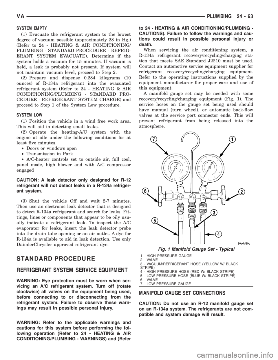
recovery/recycling/charging equipment (Fig. 1). The
service hoses on the gauge set being used should
have manual (turn wheel), or automatic back-flow
valves at the service port connector ends. This will
prevent refrigerant from being released into the
atmosphere.
MANIFOLD GAUGE SET CONNECTIONS
CAUTION: Do not use an R-12 manifold gauge set
on an R-134a system. The refrigerants are not com-
patible and system damage will result.
Fig. 1 Manifold Gauge Set - Typical
1 - HIGH PRESSURE GAUGE
2 - VALVE
3 - VACUUM/REFRIGERANT HOSE (YELLOW W/ BLACK
STRIPE)
4 - HIGH PRESSURE HOSE (RED W/ BLACK STRIPE)
5 - LOW PRESSURE HOSE (BLUE W/ BLACK STRIPE)
6 - VALVE
7 - LOW PRESSURE GAUGE
VAPLUMBING 24 - 63