2006 MERCEDES-BENZ SPRINTER engine
[x] Cancel search: enginePage 1849 of 2305
relation to the load and gear. All other pressures
required for the transmission control are derived
from the working pressure.
Lubrication Pressure (p - Sm)
At the working pressure regulating valve surplus
oil is diverted to the lubrication pressure regulating
valve, from where it is used in regulated amounts to
lubricate and cool the mechanical transmission com-
ponents and the torque converter. Furthermore, the
lubrication pressure (p-Sm) is also used to limit the
pressure in the torque converter.
Shift Pressure (p - S)
The shift pressure is determined by the shift pres-
sure regulating solenoid valve and the shift pressure
regulating valve. The shift pressure:
²Regulates the pressure in the activating shift
element during the shift phase.
²Determines together with the modulating pres-
sure the pressure reduction at the deactivating shift
element as regulated by the overlap regulating valve.
²Initializes 2nd gear in limp-home mode.
Modulating Pressure (p - Mod)
The modulating pressure influences the size of the
working pressure and determines together with the
shift pressure the pressure regulated at the overlap
regulating valve. The modulating pressure is regu-
lated at the modulating pressure regulating solenoid
valve, which is under regulating valve pressure. The
modulating pressure is variable and relative to the
engine load.
Regulating Valve / Control Valve Pressure (p - RV)
The regulating valve pressure is regulated at the
regulating valve pressure regulating valve in relation
to the working pressure (p-A) up to a maximum pres-
sure of 8 bar (116 psi). It supplies the modulating
pressure regulating solenoid valve, the shift pressure
regulating solenoid valve and the shift valve pressure
regulating valve.
Shift Valve Pressure (p - SV)
The shift valve pressure (p-SV) is derived from the
regulating valve pressure (p-RV), is regulated at the
shift valve pressure regulating valve and is then
present at the:
²1-2 and 4-5 shift solenoid valve.
²3-4 shift solenoid valve.
²2-3 shift solenoid valve.
²Torque converter lockup solenoid valve.
²3-4 and 2-3 shift pressure shift valve.
The shift valve pressure (p-SV) controls the com-
mand valves via the upshift/downshift solenoid
valves.Overlap Pressure (p - š)
The overlap pressure controls the shift component
pressure reduction during a shift phase. The pres-
sure in a shift element as it disengages is controlled
during the shift phase depending on engine load
(modulating pressure) and the pressure in the shift
element as it engages. The adjusted pressure is
inversely proportional to the transmission capability
of the shift element being engaged (controlled over-
lap).
Working Pressure Regulating Valve (Operating Pressure)
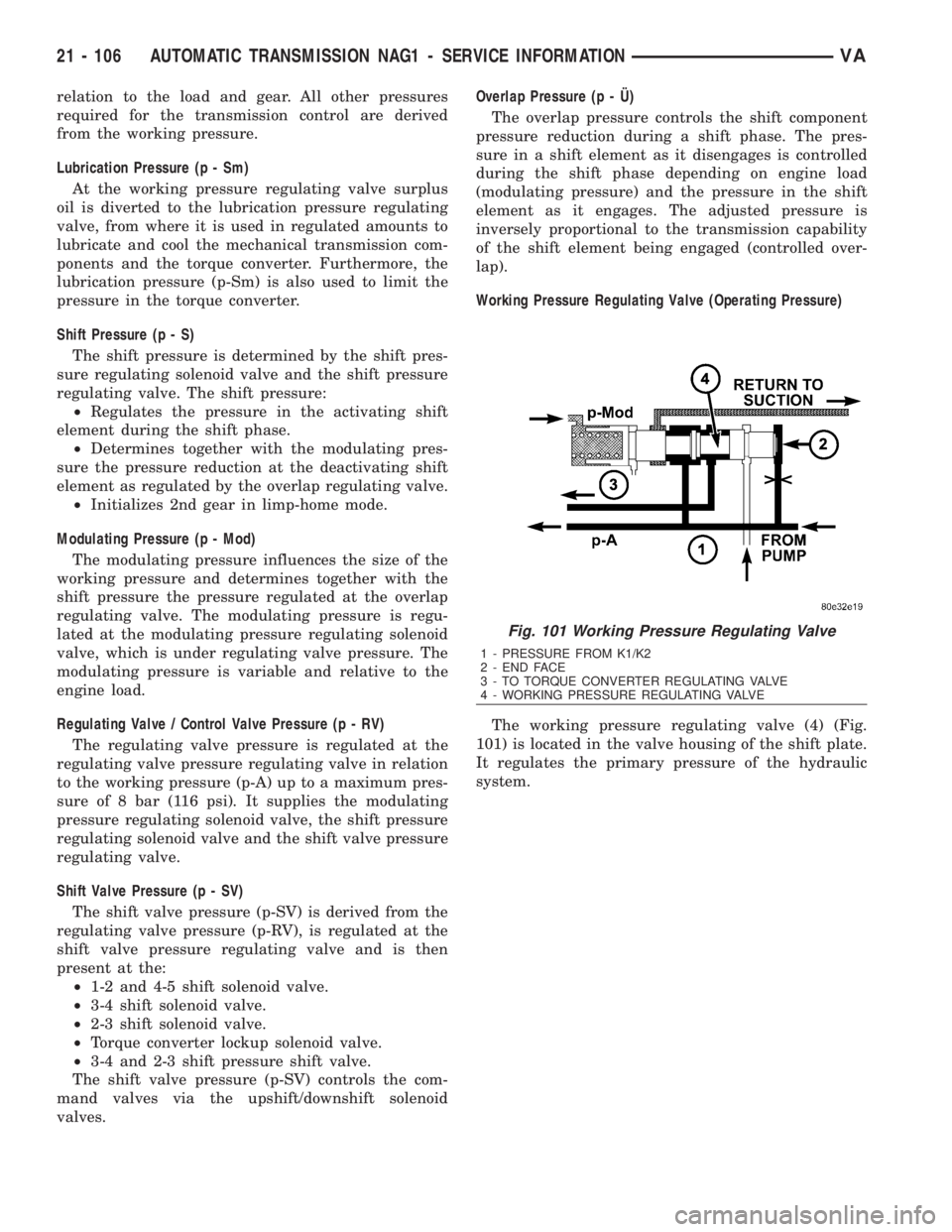
The working pressure regulating valve (4) (Fig.
101) is located in the valve housing of the shift plate.
It regulates the primary pressure of the hydraulic
system.
Fig. 101 Working Pressure Regulating Valve
1 - PRESSURE FROM K1/K2
2 - END FACE
3 - TO TORQUE CONVERTER REGULATING VALVE
4 - WORKING PRESSURE REGULATING VALVE
21 - 106 AUTOMATIC TRANSMISSION NAG1 - SERVICE INFORMATIONVA
Page 1858 of 2305
Overlap Regulating Valve
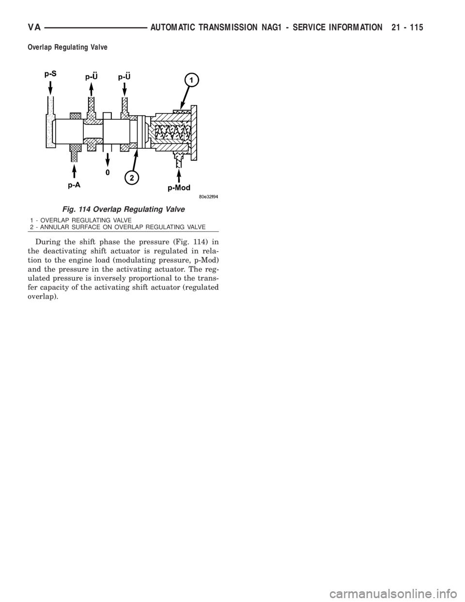
During the shift phase the pressure (Fig. 114) in
the deactivating shift actuator is regulated in rela-
tion to the engine load (modulating pressure, p-Mod)
and the pressure in the activating actuator. The reg-
ulated pressure is inversely proportional to the trans-
fer capacity of the activating shift actuator (regulated
overlap).
Fig. 114 Overlap Regulating Valve
1 - OVERLAP REGULATING VALVE
2 - ANNULAR SURFACE ON OVERLAP REGULATING VALVE
VAAUTOMATIC TRANSMISSION NAG1 - SERVICE INFORMATION 21 - 115
Page 1875 of 2305
CAUSES OF BURNT FLUID
Burnt, discolored fluid is a result of overheating
which has three primary causes.
1. Internal clutch slippage, usually caused by low
line pressure, inadequate clutch apply pressure, or
clutch seal failure.
2. A result of restricted fluid flow through the
main and/or auxiliary cooler. This condition is usu-
ally the result of a faulty or improperly installed
drainback valve, a damaged oil cooler, or severe
restrictions in the coolers and lines caused by debris
or kinked lines.
3. Heavy duty operation with a vehicle not prop-
erly equipped for this type of operation. Trailer tow-
ing or similar high load operation will overheat the
transmission fluid if the vehicle is improperly
equipped. Such vehicles should have an auxiliary
transmission fluid cooler, a heavy duty cooling sys-
tem, and the engine/axle ratio combination needed to
handle heavy loads.
FLUID CONTAMINATION
Transmission fluid contamination is generally a
result of:
²adding incorrect fluid
²failure to clean dipstick and fill tube when
checking level
²engine coolant entering the fluid
²internal failure that generates debris
²overheat that generates sludge (fluid break-
down)
²failure to replace contaminated converter after
repair
The use of non-recommended fluids can result in
transmission failure. The usual results are erratic
shifts, slippage, abnormal wear and eventual failure
due to fluid breakdown and sludge formation. Avoid
this condition by using recommended fluids only.
The dipstick cap and fill tube should be wiped
clean before checking fluid level. Dirt, grease and
other foreign material on the cap and tube could fall
into the tube if not removed beforehand. Take the
time to wipe the cap and tube clean before withdraw-
ing the dipstick.
Engine coolant in the transmission fluid is gener-
ally caused by a cooler malfunction. The only remedy
is to replace the radiator as the cooler in the radiator
is not a serviceable part. If coolant has circulated
through the transmission, an overhaul is necessary.
The torque converter should be replaced whenever
a failure generates sludge and debris. This is neces-
sary because normal converter flushing procedures
will not remove all contaminants.
STANDARD PROCEDURE
CHECK OIL LEVEL
(1) Verify that the vehicle is parked on a level sur-
face.
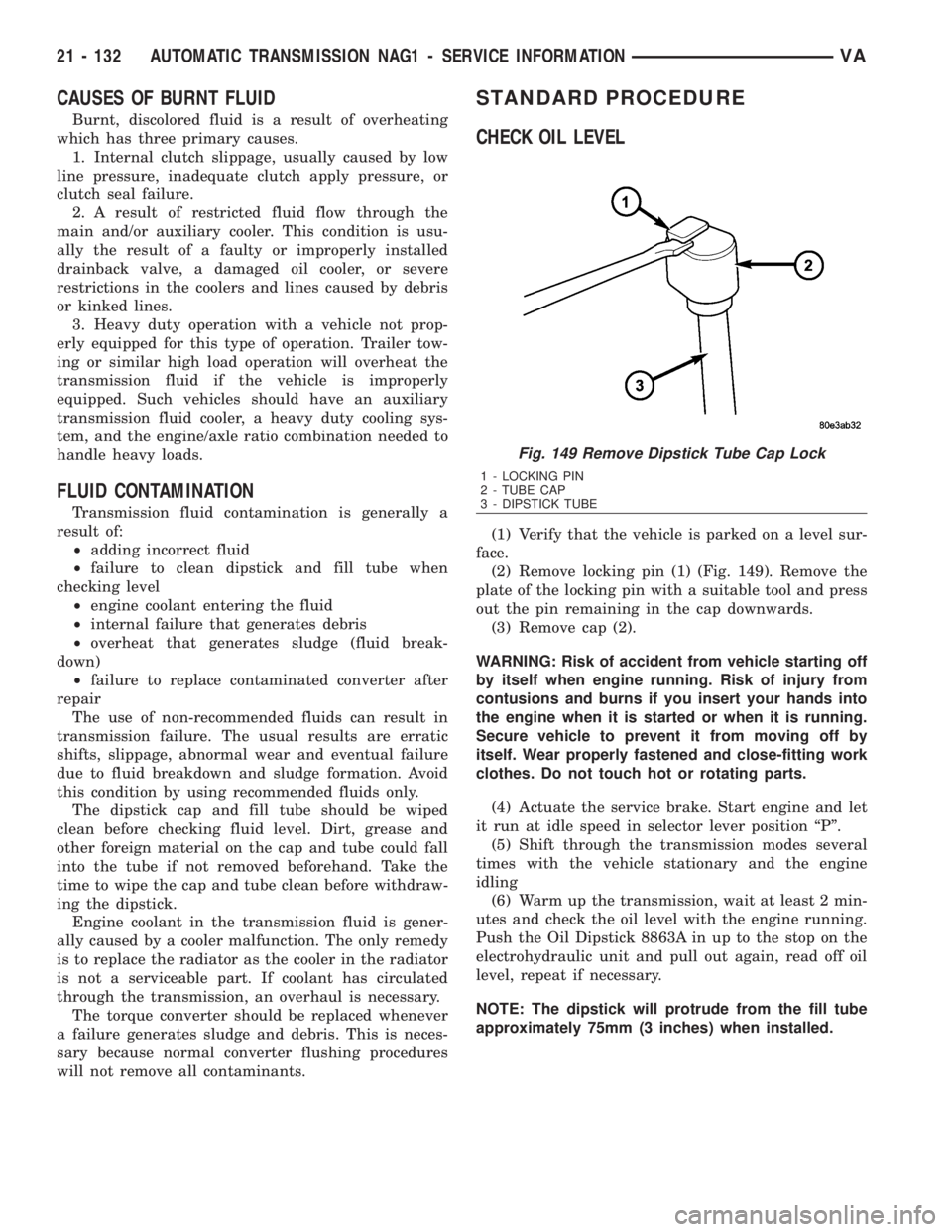
(2) Remove locking pin (1) (Fig. 149). Remove the
plate of the locking pin with a suitable tool and press
out the pin remaining in the cap downwards.
(3) Remove cap (2).
WARNING: Risk of accident from vehicle starting off
by itself when engine running. Risk of injury from
contusions and burns if you insert your hands into
the engine when it is started or when it is running.
Secure vehicle to prevent it from moving off by
itself. Wear properly fastened and close-fitting work
clothes. Do not touch hot or rotating parts.
(4) Actuate the service brake. Start engine and let
it run at idle speed in selector lever position ªPº.
(5) Shift through the transmission modes several
times with the vehicle stationary and the engine
idling
(6) Warm up the transmission, wait at least 2 min-
utes and check the oil level with the engine running.
Push the Oil Dipstick 8863A in up to the stop on the
electrohydraulic unit and pull out again, read off oil
level, repeat if necessary.
NOTE: The dipstick will protrude from the fill tube
approximately 75mm (3 inches) when installed.
Fig. 149 Remove Dipstick Tube Cap Lock
1 - LOCKING PIN
2 - TUBE CAP
3 - DIPSTICK TUBE
21 - 132 AUTOMATIC TRANSMISSION NAG1 - SERVICE INFORMATIONVA
Page 1877 of 2305
To avoid overfilling transmission after a fluid
change or overhaul, perform the following procedure:
(1) Verify that the vehicle is parked on a level sur-
face.
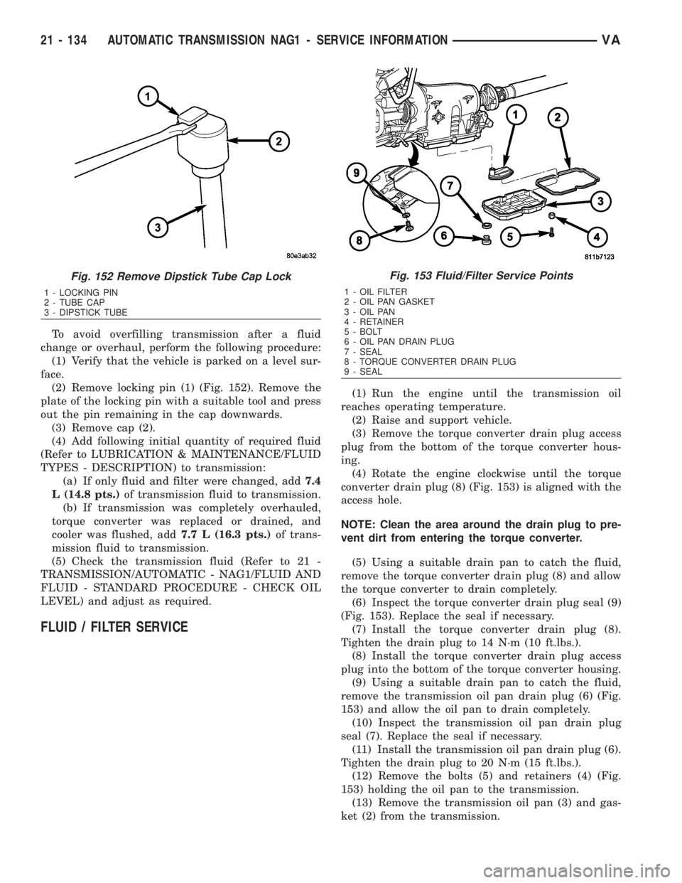
(2) Remove locking pin (1) (Fig. 152). Remove the
plate of the locking pin with a suitable tool and press
out the pin remaining in the cap downwards.
(3) Remove cap (2).
(4) Add following initial quantity of required fluid
(Refer to LUBRICATION & MAINTENANCE/FLUID
TYPES - DESCRIPTION) to transmission:
(a) If only fluid and filter were changed, add7.4
L (14.8 pts.)of transmission fluid to transmission.
(b) If transmission was completely overhauled,
torque converter was replaced or drained, and
cooler was flushed, add7.7 L (16.3 pts.)of trans-
mission fluid to transmission.
(5) Check the transmission fluid (Refer to 21 -
TRANSMISSION/AUTOMATIC - NAG1/FLUID AND
FLUID - STANDARD PROCEDURE - CHECK OIL
LEVEL) and adjust as required.
FLUID / FILTER SERVICE
(1) Run the engine until the transmission oil
reaches operating temperature.
(2) Raise and support vehicle.
(3) Remove the torque converter drain plug access
plug from the bottom of the torque converter hous-
ing.
(4) Rotate the engine clockwise until the torque
converter drain plug (8) (Fig. 153) is aligned with the
access hole.
NOTE: Clean the area around the drain plug to pre-
vent dirt from entering the torque converter.
(5) Using a suitable drain pan to catch the fluid,
remove the torque converter drain plug (8) and allow
the torque converter to drain completely.
(6) Inspect the torque converter drain plug seal (9)
(Fig. 153). Replace the seal if necessary.
(7) Install the torque converter drain plug (8).
Tighten the drain plug to 14 N´m (10 ft.lbs.).
(8) Install the torque converter drain plug access
plug into the bottom of the torque converter housing.
(9) Using a suitable drain pan to catch the fluid,
remove the transmission oil pan drain plug (6) (Fig.
153) and allow the oil pan to drain completely.
(10) Inspect the transmission oil pan drain plug
seal (7). Replace the seal if necessary.
(11) Install the transmission oil pan drain plug (6).
Tighten the drain plug to 20 N´m (15 ft.lbs.).
(12) Remove the bolts (5) and retainers (4) (Fig.
153) holding the oil pan to the transmission.
(13) Remove the transmission oil pan (3) and gas-
ket (2) from the transmission.
Fig. 152 Remove Dipstick Tube Cap Lock
1 - LOCKING PIN
2 - TUBE CAP
3 - DIPSTICK TUBE
Fig. 153 Fluid/Filter Service Points
1 - OIL FILTER
2 - OIL PAN GASKET
3 - OIL PAN
4 - RETAINER
5 - BOLT
6 - OIL PAN DRAIN PLUG
7 - SEAL
8 - TORQUE CONVERTER DRAIN PLUG
9 - SEAL
21 - 134 AUTOMATIC TRANSMISSION NAG1 - SERVICE INFORMATIONVA
Page 1881 of 2305
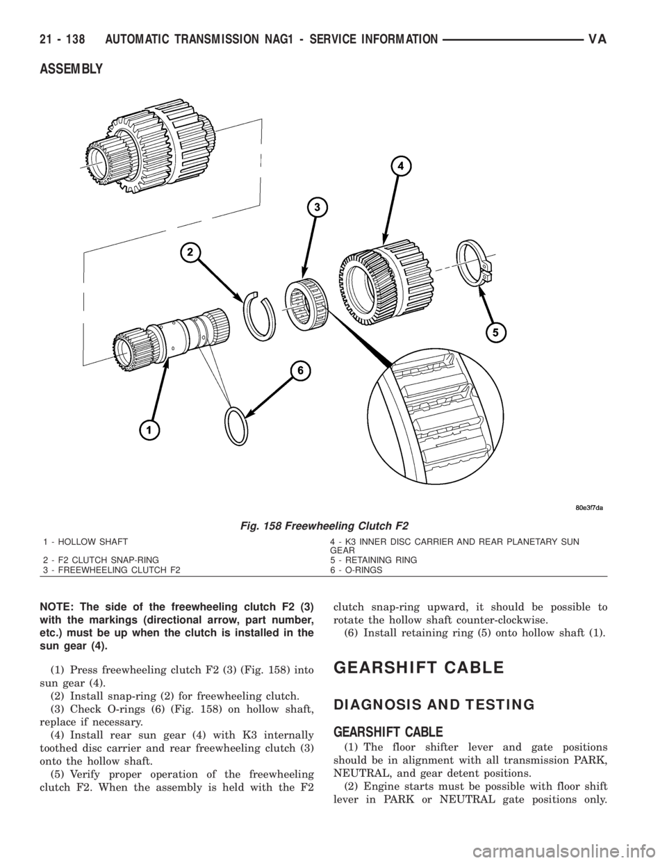
ASSEMBLY
NOTE: The side of the freewheeling clutch F2 (3)
with the markings (directional arrow, part number,
etc.) must be up when the clutch is installed in the
sun gear (4).
(1) Press freewheeling clutch F2 (3) (Fig. 158) into
sun gear (4).
(2) Install snap-ring (2) for freewheeling clutch.
(3) Check O-rings (6) (Fig. 158) on hollow shaft,
replace if necessary.
(4) Install rear sun gear (4) with K3 internally
toothed disc carrier and rear freewheeling clutch (3)
onto the hollow shaft.
(5) Verify proper operation of the freewheeling
clutch F2. When the assembly is held with the F2clutch snap-ring upward, it should be possible to
rotate the hollow shaft counter-clockwise.
(6) Install retaining ring (5) onto hollow shaft (1).
GEARSHIFT CABLE
DIAGNOSIS AND TESTING
GEARSHIFT CABLE
(1) The floor shifter lever and gate positions
should be in alignment with all transmission PARK,
NEUTRAL, and gear detent positions.
(2) Engine starts must be possible with floor shift
lever in PARK or NEUTRAL gate positions only.
Fig. 158 Freewheeling Clutch F2
1 - HOLLOW SHAFT 4 - K3 INNER DISC CARRIER AND REAR PLANETARY SUN
GEAR
2 - F2 CLUTCH SNAP-RING 5 - RETAINING RING
3 - FREEWHEELING CLUTCH F2 6 - O-RINGS
21 - 138 AUTOMATIC TRANSMISSION NAG1 - SERVICE INFORMATIONVA
Page 1882 of 2305
Engine starts must not be possible in any other gear
position.
(3) With floor shift lever handle push-button not
depressed and lever in:
(a) PARK position - Apply forward force on cen-
ter of handle and remove pressure. Engine starts
must be possible.
(b) PARK position - Apply rearward force on cen-
ter of handle and remove pressure. Engine starts
must be possible.
(c) NEUTRAL position - Normal position. Engine
starts must be possible.
(d) NEUTRAL position - Engine running and
brakes applied, apply forward force on center of
shift handle. Transmission shall not be able to shift
from NEUTRAL to REVERSE.
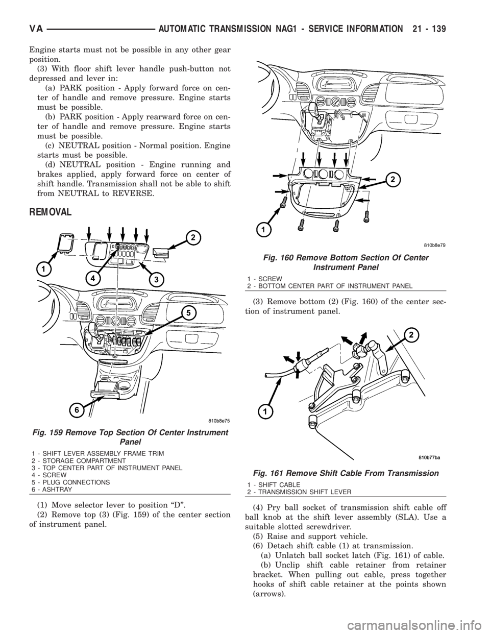
REMOVAL
(1) Move selector lever to position ªDº.
(2) Remove top (3) (Fig. 159) of the center section
of instrument panel.(3) Remove bottom (2) (Fig. 160) of the center sec-
tion of instrument panel.
(4) Pry ball socket of transmission shift cable off
ball knob at the shift lever assembly (SLA). Use a
suitable slotted screwdriver.
(5) Raise and support vehicle.
(6) Detach shift cable (1) at transmission.
(a) Unlatch ball socket latch (Fig. 161) of cable.
(b) Unclip shift cable retainer from retainer
bracket. When pulling out cable, press together
hooks of shift cable retainer at the points shown
(arrows).
Fig. 159 Remove Top Section Of Center Instrument
Panel
1 - SHIFT LEVER ASSEMBLY FRAME TRIM
2 - STORAGE COMPARTMENT
3 - TOP CENTER PART OF INSTRUMENT PANEL
4 - SCREW
5 - PLUG CONNECTIONS
6 - ASHTRAY
Fig. 160 Remove Bottom Section Of Center
Instrument Panel
1 - SCREW
2 - BOTTOM CENTER PART OF INSTRUMENT PANEL
Fig. 161 Remove Shift Cable From Transmission
1 - SHIFT CABLE
2 - TRANSMISSION SHIFT LEVER
VAAUTOMATIC TRANSMISSION NAG1 - SERVICE INFORMATION 21 - 139
Page 1897 of 2305
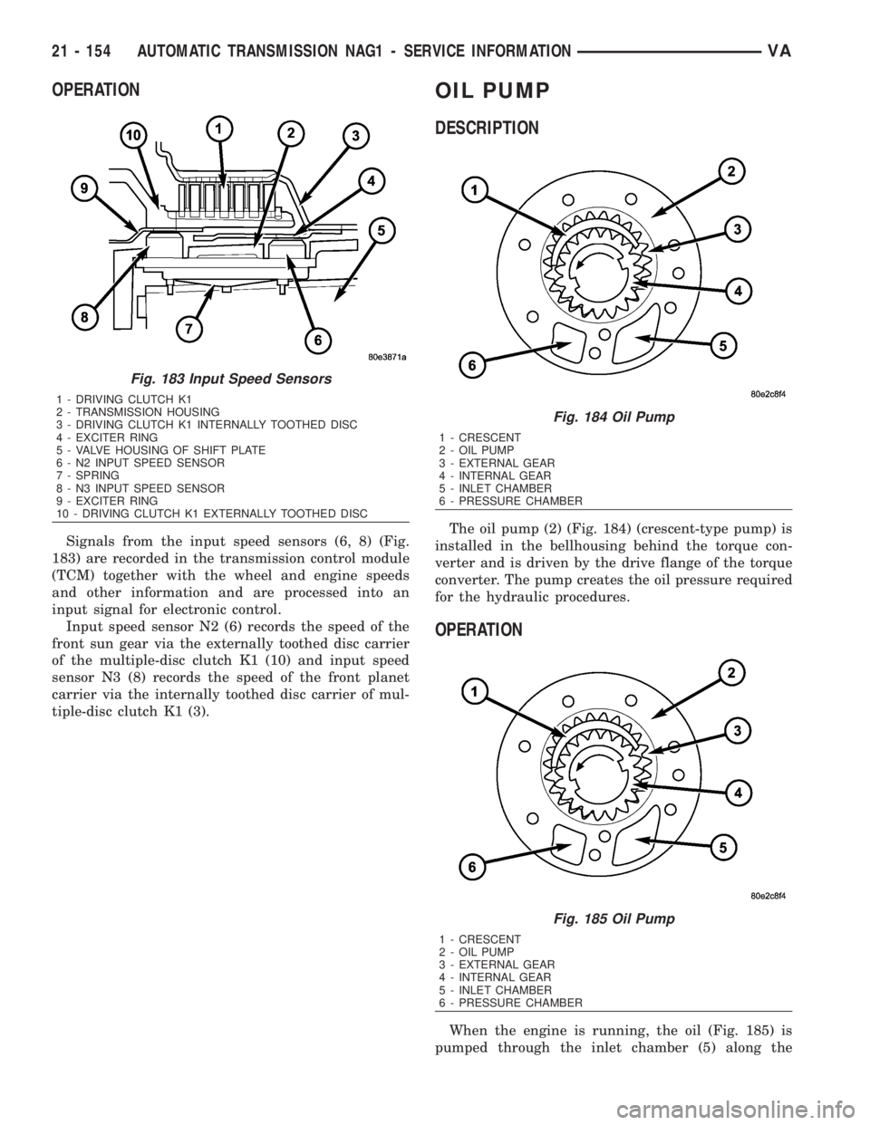
OPERATION
Signals from the input speed sensors (6, 8) (Fig.
183) are recorded in the transmission control module
(TCM) together with the wheel and engine speeds
and other information and are processed into an
input signal for electronic control.
Input speed sensor N2 (6) records the speed of the
front sun gear via the externally toothed disc carrier
of the multiple-disc clutch K1 (10) and input speed
sensor N3 (8) records the speed of the front planet
carrier via the internally toothed disc carrier of mul-
tiple-disc clutch K1 (3).
OIL PUMP
DESCRIPTION
The oil pump (2) (Fig. 184) (crescent-type pump) is
installed in the bellhousing behind the torque con-
verter and is driven by the drive flange of the torque
converter. The pump creates the oil pressure required
for the hydraulic procedures.
OPERATION
When the engine is running, the oil (Fig. 185) is
pumped through the inlet chamber (5) along the
Fig. 183 Input Speed Sensors
1 - DRIVING CLUTCH K1
2 - TRANSMISSION HOUSING
3 - DRIVING CLUTCH K1 INTERNALLY TOOTHED DISC
4 - EXCITER RING
5 - VALVE HOUSING OF SHIFT PLATE
6 - N2 INPUT SPEED SENSOR
7 - SPRING
8 - N3 INPUT SPEED SENSOR
9 - EXCITER RING
10 - DRIVING CLUTCH K1 EXTERNALLY TOOTHED DISC
Fig. 184 Oil Pump
1 - CRESCENT
2 - OIL PUMP
3 - EXTERNAL GEAR
4 - INTERNAL GEAR
5 - INLET CHAMBER
6 - PRESSURE CHAMBER
Fig. 185 Oil Pump
1 - CRESCENT
2 - OIL PUMP
3 - EXTERNAL GEAR
4 - INTERNAL GEAR
5 - INLET CHAMBER
6 - PRESSURE CHAMBER
21 - 154 AUTOMATIC TRANSMISSION NAG1 - SERVICE INFORMATIONVA
Page 1908 of 2305
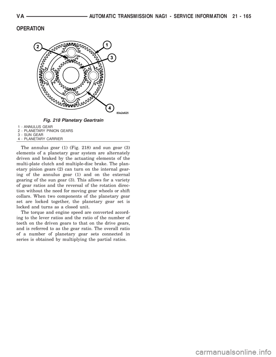
OPERATION
The annulus gear (1) (Fig. 218) and sun gear (3)
elements of a planetary gear system are alternately
driven and braked by the actuating elements of the
multi-plate clutch and multiple-disc brake. The plan-
etary pinion gears (2) can turn on the internal gear-
ing of the annulus gear (1) and on the external
gearing of the sun gear (3). This allows for a variety
of gear ratios and the reversal of the rotation direc-
tion without the need for moving gear wheels or shift
collars. When two components of the planetary gear
set are locked together, the planetary gear set is
locked and turns as a closed unit.
The torque and engine speed are converted accord-
ing to the lever ratios and the ratio of the number of
teeth on the driven gears to that on the drive gears,
and is referred to as the gear ratio. The overall ratio
of a number of planetary gear sets connected in
series is obtained by multiplying the partial ratios.
Fig. 218 Planetary Geartrain
1 - ANNULUS GEAR
2 - PLANETARY PINION GEARS
3 - SUN GEAR
4 - PLANETARY CARRIER
VAAUTOMATIC TRANSMISSION NAG1 - SERVICE INFORMATION 21 - 165