2006 MERCEDES-BENZ SPRINTER oil level
[x] Cancel search: oil levelPage 1877 of 2305
To avoid overfilling transmission after a fluid
change or overhaul, perform the following procedure:
(1) Verify that the vehicle is parked on a level sur-
face.
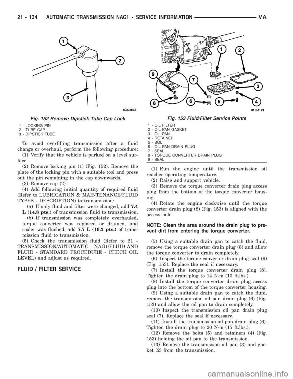
(2) Remove locking pin (1) (Fig. 152). Remove the
plate of the locking pin with a suitable tool and press
out the pin remaining in the cap downwards.
(3) Remove cap (2).
(4) Add following initial quantity of required fluid
(Refer to LUBRICATION & MAINTENANCE/FLUID
TYPES - DESCRIPTION) to transmission:
(a) If only fluid and filter were changed, add7.4
L (14.8 pts.)of transmission fluid to transmission.
(b) If transmission was completely overhauled,
torque converter was replaced or drained, and
cooler was flushed, add7.7 L (16.3 pts.)of trans-
mission fluid to transmission.
(5) Check the transmission fluid (Refer to 21 -
TRANSMISSION/AUTOMATIC - NAG1/FLUID AND
FLUID - STANDARD PROCEDURE - CHECK OIL
LEVEL) and adjust as required.
FLUID / FILTER SERVICE
(1) Run the engine until the transmission oil
reaches operating temperature.
(2) Raise and support vehicle.
(3) Remove the torque converter drain plug access
plug from the bottom of the torque converter hous-
ing.
(4) Rotate the engine clockwise until the torque
converter drain plug (8) (Fig. 153) is aligned with the
access hole.
NOTE: Clean the area around the drain plug to pre-
vent dirt from entering the torque converter.
(5) Using a suitable drain pan to catch the fluid,
remove the torque converter drain plug (8) and allow
the torque converter to drain completely.
(6) Inspect the torque converter drain plug seal (9)
(Fig. 153). Replace the seal if necessary.
(7) Install the torque converter drain plug (8).
Tighten the drain plug to 14 N´m (10 ft.lbs.).
(8) Install the torque converter drain plug access
plug into the bottom of the torque converter housing.
(9) Using a suitable drain pan to catch the fluid,
remove the transmission oil pan drain plug (6) (Fig.
153) and allow the oil pan to drain completely.
(10) Inspect the transmission oil pan drain plug
seal (7). Replace the seal if necessary.
(11) Install the transmission oil pan drain plug (6).
Tighten the drain plug to 20 N´m (15 ft.lbs.).
(12) Remove the bolts (5) and retainers (4) (Fig.
153) holding the oil pan to the transmission.
(13) Remove the transmission oil pan (3) and gas-
ket (2) from the transmission.
Fig. 152 Remove Dipstick Tube Cap Lock
1 - LOCKING PIN
2 - TUBE CAP
3 - DIPSTICK TUBE
Fig. 153 Fluid/Filter Service Points
1 - OIL FILTER
2 - OIL PAN GASKET
3 - OIL PAN
4 - RETAINER
5 - BOLT
6 - OIL PAN DRAIN PLUG
7 - SEAL
8 - TORQUE CONVERTER DRAIN PLUG
9 - SEAL
21 - 134 AUTOMATIC TRANSMISSION NAG1 - SERVICE INFORMATIONVA
Page 1878 of 2305
(14) Remove the transmission oil filter (1) and
o-ring from the electrohydraulic control unit.
(15) Clean the inside of the oil pan (3) of any
debris. Inspect the oil pan gasket (2) and replace if
necessary.
(16) Install a new oil filter (1) and o-ring into the
electrohydraulic control unit.
(17) Install the oil pan (3) and gasket (2) onto the
transmission.
(18) Install the oil pan bolts (5) and retainers (4).
Torque the bolts to 8 N´m (70 in.lbs.).
(19) Lower the vehicle and add 7.0 L (7.4 qts.) of
transmission fluid to the transmission.
(20) Check the oil level (Refer to 21 - TRANSMIS-
SION/AUTOMATIC - NAG1/FLUID AND FILTER -
STANDARD PROCEDURE - CHECK OIL LEVEL).
FREEWHEELING CLUTCH
DESCRIPTION
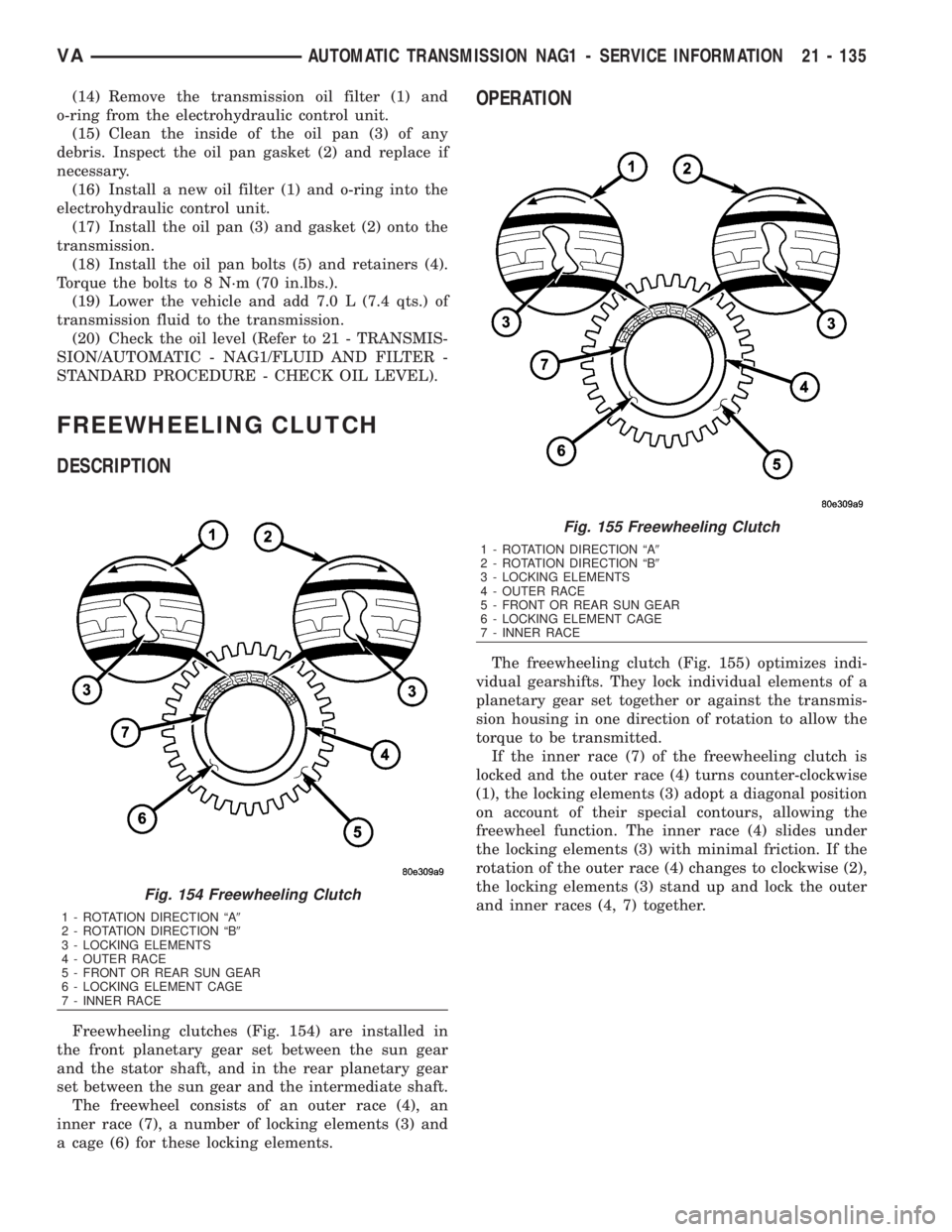
Freewheeling clutches (Fig. 154) are installed in
the front planetary gear set between the sun gear
and the stator shaft, and in the rear planetary gear
set between the sun gear and the intermediate shaft.
The freewheel consists of an outer race (4), an
inner race (7), a number of locking elements (3) and
a cage (6) for these locking elements.
OPERATION
The freewheeling clutch (Fig. 155) optimizes indi-
vidual gearshifts. They lock individual elements of a
planetary gear set together or against the transmis-
sion housing in one direction of rotation to allow the
torque to be transmitted.
If the inner race (7) of the freewheeling clutch is
locked and the outer race (4) turns counter-clockwise
(1), the locking elements (3) adopt a diagonal position
on account of their special contours, allowing the
freewheel function. The inner race (4) slides under
the locking elements (3) with minimal friction. If the
rotation of the outer race (4) changes to clockwise (2),
the locking elements (3) stand up and lock the outer
and inner races (4, 7) together.
Fig. 154 Freewheeling Clutch
1 - ROTATION DIRECTION ªA9
2 - ROTATION DIRECTION ªB9
3 - LOCKING ELEMENTS
4 - OUTER RACE
5 - FRONT OR REAR SUN GEAR
6 - LOCKING ELEMENT CAGE
7 - INNER RACE
Fig. 155 Freewheeling Clutch
1 - ROTATION DIRECTION ªA9
2 - ROTATION DIRECTION ªB9
3 - LOCKING ELEMENTS
4 - OUTER RACE
5 - FRONT OR REAR SUN GEAR
6 - LOCKING ELEMENT CAGE
7 - INNER RACE
VAAUTOMATIC TRANSMISSION NAG1 - SERVICE INFORMATION 21 - 135
Page 2040 of 2305
When the outside air contains smoke, odors, high
humidity, or if rapid cooling is desired, interior air
can by recirculated by selecting the Recirculation
Mode with the mode control knob. The mode control
knob operates the recirculation door through use of a
vacuum actuator. When the Recirculation Mode is
selected, the recirculation door is closed to prevent
outside air from entering the passenger compart-
ment.
To maintain minimum evaporator temperature and
prevent evaporator freezing, an evaporator tempera-
ture sensor is used.
The A/C system is designed for the use of non-CFC,
R-134a refrigerant only and uses an expansion valve
to meter refrigerant flow to the evaporator.
DIAGNOSIS AND TESTING
A / C PERFORMANCE
The A/C system is designed to provide the passen-
ger compartment with low temperature and low
humidity air. The A/C evaporator, located in the
HVAC housing is cooled to temperatures near the
freezing point. As warm damp air passes over the
fins of the A/C evaporator, the air transfers its heat
to the refrigerant in the evaporator coils and the
moisture in the air condenses on the evaporator fins.
During periods of high heat and humidity, an A/C
system will be more effective in the Recirculation
mode (max-A/C). With the system in the Recircula-
tion mode, only air from the passenger compartment
passes through the A/C evaporator. As the passenger
compartment air dehumidifies, the A/C system per-
formance levels rise.
Humidity has an important bearing on the temper-
ature of the air delivered to the interior of the vehi-
cle. It is important to understand the effect that
humidity has on the performance of the A/C system.
When humidity is high, the A/C evaporator has to
perform a double duty. It must lower the air temper-
ature, and it must lower the temperature of the
moisture in the air that condenses on the evaporator
fins. Condensing the moisture in the air transfers
heat energy into the evaporator fins and coils. This
reduces the amount of heat the A/C evaporator can
absorb from the air. High humidity greatly reduces
the ability of the A/C evaporator to lower the temper-
ature of the air.
However, evaporator capacity used to reduce the
amount of moisture in the air is not wasted. Wring-
ing some of the moisture out of the air entering the
vehicle adds to the comfort of the passengers.
Although, an owner may expect too much from their
A/C system on humid days. A performance test is the
best way to determine whether the system is per-
forming up to design standards. This test also pro-
vides valuable clues as to the possible cause oftrouble with the A/C system. The ambient air tem-
perature in the location where the vehicle will be
tested must be a minimum of 21É C (70É F) for this
test.
A / C PERFORMANCE TEST
WARNING: Refer to the applicable warnings and
cautions for this system before performing the fol-
lowing operation (Refer to 24 - HEATING & AIR
CONDITIONING/PLUMBING - WARNINGS) and (Refer
to 24 - HEATING & AIR CONDITIONING/PLUMBING -
CAUTIONS). Failure to follow the warnings and cau-
tions could result in possible personal injury or
death.
NOTE: Very specific instructions and conditions
pertain to this procedure which are significantly dif-
ferent than procedures used in other vehicle appli-
cations. Follow each step in the order they are
presented. Do not skip steps or change conditions
from those stated or results will be adversely
affected and invalid.
NOTE: When connecting the service equipment
coupling to the line fitting, verify that the valve of
the coupling is fully closed. This will reduce the
amount of effort required to make the connection.
(1) Check for diagnostic trouble codes using a
DRBIIItscan tool. If no DTCs are found in the
engine control module (ECM), go to Step 2. If any
DTCs are found, repair as required, then proceed to
Step 2.
(2) Place the vehicle in the shade and operate the
heating-A/C system under the following conditions.
²Engine at idle at operating temperature
²All doors or windows open
²Transaxle in Neutral
²All A/C duct louvers open
²A/C-heater controls set to fresh air (NOT Recir-
culate), full cool, panel mode, high blower and with
A/C compressor engaged.
NOTE: The A/C compressor clutch is de-energized
under any of the following conditions:
²Restricted compressor (thermal fuse in the pul-
ley)
²Low pressure in the system
²Low evaporator temperature
²Hard acceleration (WOT)
²High coolant temperatures
(3) Insert a thermometer in the driver side center
panel air outlet and operate the A/C system until the
thermometer temperature stabilizes.
VAHEATING & AIR CONDITIONING 24 - 3
Page 2041 of 2305
(4) With the A/C compressor clutch engaged, duct
temperature should not be less than 2É C (35É F) or
more than 12É C (54É F). The compressor clutch may
cycle, depending upon the ambient temperature and
humidity. If the clutch cycles, use the readings
obtained before the clutch disengaged.
(5) If the A/C compressor clutch has not cycled off
and the duct temperature is less than 2É C (35É F),
check the evaporator temperature sensor and circuitby performing the ATC Function Test (Refer to 24 -
HEATING & AIR CONDITIONING - DIAGNOSIS
AND TESTING - ATC FUNCTION TEST).
(6) If the air outlet temperature fails to meet the
specifications, refer to the A/C System Diagnosis
chart.
A/C SYSTEM DIAGNOSIS
Condition Possible Causes Correction
Rapid A/C compressor clutch
cycling (ten or more cycles
per minute).Very low refrigerant system
charge.See Refrigerant System Leaks in this group.
Test the refrigerant system for leaks. Repair,
evacuate and charge the refrigerant system, if
required.
Equal pressures, but the
compressor clutch does not
engage.1. No refrigerant in the refrig-
erant system.1. See Refrigerant System Leaks in this
group. Test the refrigerant system for leaks.
Repair, evacuate and charge the refrigerant
system, if required.
2. Faulty fuse. 2. Check the fuses in the Power distribution
block and junction block. Repair the shorted
circuit or component and replace the fuses, if
required. Refer to Group 8.
3. Faulty A/C compressor
clutch coil.3. See A/C Compressor Clutch Coil in this
group. Test the compressor clutch coil and
replace, if required.
4. Improperly installed or faulty
evaporator temperature sensor.4. See Evaporator Temperature Sensor in this
group. Test the sensor and replace, if re-
quired.
5. Faulty A/C pressure trans-
ducer.5. See A/C Pressure Transducer in this
group. Test the sensor and replace, if re-
quired.
6. Faulty engine Control Mod-
ule (ECM).6. Refer to Group 9 - Engine Electrical Diag-
nostics for testing of the ECM. Test the ECM
and replace, if required.
Normal pressures, but A/C
Performance Test air temper-
atures at center panel outlet
are too high.1. Excessive refrigerant oil in
system.1. See Refrigerant Oil Level in this group.
Recover the refrigerant from the refrigerant
system and inspect the refrigerant oil content.
Restore the refrigerant oil to the proper level,
if required.
2. Blend door cable improperly
installed or faulty.2. See Mode Door Cables in this group. In-
spect the cable for proper operation and re-
place, if required.
3. Blend-air door(s) inoperative
or sealing improperly.3. See HVAC Housing in this group. Inspect
the blend-air door(s) for proper operation and
sealing. Repair if required.
24 - 4 HEATING & AIR CONDITIONINGVA
Page 2049 of 2305
front cover of the compressor. Be certain that the
snap ring is properly fully and properly seated in the
groove.
(6) If the original clutch plate and clutch pulley
are to be reused, reinstall the original shim(s) on the
compressor shaft against the shoulder. If a new
clutch plate and/or clutch pulley are being used,
install a trial stack of shims 1.0 mm (0.040 in.) thick
on the compressor shaft against the shoulder.
(7) Install the clutch plate onto the compressor
shaft.
(8) Install and tighten the compressor shaft bolt. If
necessary, a band-type oil filter wrench or a strap
wrench can be placed around the clutch plate to aid
in bolt tightening. Tighten the bolt to 17.5 N´m (155
in. lbs.).
NOTE: The shims may compress after tightening
the shaft bolt. Check the air gap in four or more
places to verify the air gap is still correct. Spin the
pulley before performing a final check of the air
gap.
(9) If a new clutch plate and/or clutch pulley are
being installed, the air gap between the clutch plate
and clutch pulley must be checked (Refer to 24 -
HEATING & AIR CONDITIONING/CONTROLS/A/C
COMPRESSOR CLUTCH - STANDARD PROCE-
DURE).
(10) Install the retainer that secures the compres-
sor clutch coil lead to the top of the compressor.
(11) Reconnect the engine wire harness connector
to the clutch coil lead on the top of the compressor.
(12) Reinstall the serpentine accessory drive belt
(Refer to 7 - COOLING/ACCESSORY DRIVE/DRIVE
BELTS - INSTALLATION).
(13) Reconnect the battery negative cable.
(14) If a new clutch plate and/or clutch pulley are
being installed, the new clutch components must be
burnished (Refer to 24 - HEATING & AIR CONDI-
TIONING/CONTROLS/A/C COMPRESSOR CLUTCH
- STANDARD PROCEDURE).
A / C COMPRESSOR CLUTCH
COIL
DIAGNOSIS AND TESTING
A / C COMPRESSOR CLUTCH COIL
The air conditioning compressor clutch coil electri-
cal circuit is controlled by the ATC control module
which is integral to the heater-A/C control. Begin
testing of a suspected compressor clutch coil problem
by performing the ATC Function Test using the
DRBIIItscan tool.PRELIMINARY CHECKS
(1) If no diagnostic trouble codes (DTCs) are found
in the A/C-heater control or the powertrain control
module (PCM), go to Step 2. If any DTCs are found,
repair as required.
(2) If the A/C compressor clutch still will not
engage, verify the refrigerant charge level (Refer to
24 - HEATING & AIR CONDITIONING/PLUMBING
- DIAGNOSIS AND TESTING - REFRIGERANT
SYSTEM LEAKS). If the refrigerant charge level is
OK, go to TESTS. If the refrigerant charge level is
not OK, adjust the refrigerant charge as required.
TESTS
(1) Verify the battery state of charge (Refer to 8 -
ELECTRICAL/BATTERY SYSTEM/BATTERY -
DIAGNOSIS AND TESTING).
(2) Connect an ammeter (0 to 10 ampere scale
selected) in series with the clutch coil feed terminal.
Connect a voltmeter (0 to 20 volt scale selected) to
measure voltage across the battery and the clutch
coil.
(3) With the A/C-heater control in the A/C mode
and the blower motor at low speed, start the engine
and allow it to run at a normal idle speed.
(4) The A/C compressor clutch should engage
immediately, and the clutch coil supply voltage
should be within two volts of the battery voltage. If
the coil supply voltage is OK, go to Step 5. If the coil
supply voltage is not within two volts of battery volt-
age, test the clutch coil feed circuit for excessive volt-
age drop and repair as necessary.
(5) For the acceptable A/C clutch coil current draw
specifications refer to 24 - HEATING & AIR CONDI-
TIONING - SPECIFICATIONS. Specifications apply
for a work area temperature of 21É C (70É F). If volt-
age is more than 12.5 volts, add electrical loads by
turning on electrical accessories until voltage reads
below 12.5 volts.
(a) If the A/C clutch coil current reading is zero,
the coil is open and must be replaced.
(b) If the A/C clutch coil current reading is above
specifications, the coil is shorted and must be
replaced.
A / C HEATER CONTROL
DESCRIPTION
This ATC system uses a combination of electrical
and mechanical controls. These controls provide the
vehicle operator with a number of setting options to
help control the climate and comfort within the vehi-
cle.
The A/C-heater control is located on the instrument
panel inboard of the steering column and below the
24 - 12 CONTROLS-FRONTVA
Page 2054 of 2305
AMBIENT TEMPERATURE SEN-
SOR
DESCRIPTION
The ambient air temperature sensor is a variable
resistor that monitors the air temperature outside of
the vehicle. The ambient air temperature sensor is
connected to the instrument cluster through a two-
wire harness lead and connector of the vehicle elec-
trical system (Fig. 13). The instrument cluster sends
out a message on the CAN bus to the ATC control
module which uses the sensor data to maintain opti-
mum cabin temperature levels.
The ambient air temperature sensor is mounted to
the front licence plate bracket by three integral
retaining tabs.
OPERATION
The ambient temperature sensor is a variable
resistor that operates on a five-volt reference signal
sent to it by the instrument cluster. The resistance in
the sensor changes as temperature changes. Based
upon the resistance in the sensor, the instrument
cluster sends the ATC control module a specific volt-
age on the temperature sensor signal circuit, which
is programmed to correspond to a specific tempera-
ture.
The ambient temperature sensor is diagnosed
using the DRBIIItscan tool. Refer to Body Diagnos-
tic Procedures.
The ambient temperature sensor cannot be
adjusted or repaired and, if faulty or damaged, it
must be replaced.
REMOVAL
(1) Disconnect and isolate the battery negative
cable.
(2) Remove the front license plate bracket (Refer
to 23 - BODY/EXTERIOR/LICENSE PLATE
BRACKET - REMOVAL).
(3) Disconnect the wire harness connector from the
ambient temperature sensor (Fig. 14).
(4) Disengage the sensor retaining tabs and
remove the ambient temperature sensor from the
front license plate bracket.
INSTALLATION
(1) Install the ambient temperature sensor onto
the front license plate bracket. Make sure the retain-
ing tabs are fully engaged.
(2) Connect the wire harness connector to the
ambient temperature sensor.
(3) Install the front license plate bracket (Refer to
23 - BODY/EXTERIOR/LICENSE PLATE BRACKET
- INSTALLATION).
(4) Reconnect the battery negative cable.
BLOWER MOTOR RESISTOR
DESCRIPTION
This temperature control system uses a blower
motor resistor (Fig. 15). The blower motor resistor is
mounted to the top of ventilation housing located in
the engine compartment. The blower motor resistor
consists of a molded plastic mounting plate with an
integral retaining tab and wire connector receptacle.
Concealed behind the mounting plate are coiled resis-
tor wires contained within a ceramic heat sink.
Fig. 13 Ambient Air Temperature Sensor
1 - AMBIENT TEMPERATURE SENSOR
2 - WIRE HARNESS CONNECTOR
3 - RETAINING TABS (3)
Fig. 14 Ambient Temperature Sensor
1 - AMBIENT TEMPERATURE SENSOR
2 - FRONT LICENSE PLATE BRACKET
VACONTROLS-FRONT 24 - 17
Page 2097 of 2305
PLUMBING
TABLE OF CONTENTS
page page
PLUMBING
DESCRIPTION.........................61
OPERATION...........................61
WARNINGS...........................61
CAUTIONS............................62
DIAGNOSIS AND TESTING
REFRIGERANT SYSTEM LEAKS..........62
STANDARD PROCEDURE
REFRIGERANT SYSTEM SERVICE
EQUIPMENT.........................63
REFRIGERANT SYSTEM RECOVERY......64
REFRIGERANT SYSTEM EVACUATE......64
REFRIGERANT SYSTEM CHARGE........64
A/C COMPRESSOR
DESCRIPTION.........................66
OPERATION...........................66
DIAGNOSIS AND TESTING
A/C COMPRESSOR NOISE..............66
REMOVAL
DENSO 7SBU16C A/C COMPRESSOR.....67
DENSO 10S17 A/C COMPRESSOR........68
INSTALLATION
DENSO 7SBU16C A/C COMPRESSOR.....68
DENSO 10S17 A/C COMPRESSOR........69
A/C CONDENSER
DESCRIPTION.........................69
OPERATION...........................69
REMOVAL.............................70
INSTALLATION.........................70
A/C DISCHARGE LINE
REMOVAL.............................71
INSTALLATION.........................71
A/C EVAPORATOR
DESCRIPTION.........................72
OPERATION...........................72
REMOVAL.............................72
INSTALLATION.........................73
A/C EXPANSION VALVE
DESCRIPTION.........................73
OPERATION...........................73
DIAGNOSIS AND TESTING
A/C EXPANSION VALVE................74
REMOVAL.............................74
INSTALLATION.........................74
ELECTRIC COOLANT PUMP
DESCRIPTION.........................75
OPERATION...........................75
REMOVAL.............................75
INSTALLATION.........................76HEATER CORE
DESCRIPTION.........................76
OPERATION...........................76
REMOVAL.............................76
INSTALLATION.........................77
LIQUID LINE
REMOVAL.............................77
INSTALLATION.........................79
RECEIVER/DRIER
DESCRIPTION.........................79
OPERATION...........................79
REMOVAL.............................80
INSTALLATION.........................80
REFRIGERANT
DESCRIPTION.........................80
OPERATION...........................80
REFRIGERANT OIL
DESCRIPTION.........................81
OPERATION...........................81
STANDARD PROCEDURE
REFRIGERANT OIL LEVEL..............81
SUCTION LINE
REMOVAL.............................81
INSTALLATION.........................82
WAT E R VA LV E
REMOVAL.............................83
INSTALLATION.........................83
REAR A/C CONDENSER FAN
REMOVAL.............................83
INSTALLATION.........................84
REAR A/C EVAPORATOR
REMOVAL.............................84
INSTALLATION.........................85
REAR A/C EXPANSION VALVE
DESCRIPTION.........................85
OPERATION...........................85
REMOVAL.............................86
INSTALLATION.........................87
REAR DISCHARGE LINE
DESCRIPTION.........................88
REMOVAL.............................88
INSTALLATION.........................90
REAR LIQUID LINE
DESCRIPTION.........................91
REMOVAL.............................91
INSTALLATION.........................93
REAR RECEIVER/DRIER
REMOVAL.............................94
INSTALLATION.........................94
24 - 60 PLUMBINGVA
Page 2099 of 2305
CAUTIONS
CAUTION: Never add R-12 to a refrigerant system
designed to use R-134a. Do not use R-12 equipment
or parts on a R-134a A/C system. These refrigerants
are not compatible and damage to the A/C system
will result.
CAUTION: Never use R-12 refrigerant oil in a A/C
system designed to use R-134a refrigerant oil.
These refrigerant oils are not compatible and dam-
age to the A/C system will result.
CAUTION: The use of A/C system sealers may
result in damage to A/C refrigerant recovery/evacu-
ation/recharging equipment and/or A/C system.
Many federal, state/provincial and local regulations
prohibit the recharge of A/C systems with known
leaks. DaimlerChrysler recommends the detection
of A/C system leaks through the use of approved
leak detectors and fluorescent leak detection dyes.
Vehicles found with A/C system sealers should be
treated as contaminated and replacement of the
entire A/C refrigerant system is recommended. A/C
systems found to be contaminated with A/C system
sealers, A/C stop-leak products or seal conditioners
voids the warranty for the A/C system.
CAUTION: Recover the refrigerant before opening
any fitting or connection. Open the fittings with
caution, even after the system has been dis-
charged. Never open or loosen a connection before
recovering the refrigerant.
CAUTION: If equipped, do not remove the second-
ary retention clip from any spring-lock coupler con-
nection while the refrigerant system is under
pressure. Recover the refrigerant before removing
the secondary retention clip. Open the fittings with
caution, even after the system has been dis-
charged. Never open or loosen a connection before
recovering the refrigerant.
CAUTION: The internal parts of the A/C system will
remain stable as long as moisture-free refrigerant
and refrigerant oil is used. Abnormal amounts of
dirt, moisture or air can upset the chemical stability.
This may cause operational troubles or even seri-
ous damage if present in more than very small
quantities. Before disconnecting a component,
clean the outside of the fittings thoroughly to pre-
vent contamination from entering the refrigerant
system. Keep service tools and the work area clean.
Do not open the refrigerant system or uncap areplacement component until you are ready to ser-
vice the system. Immediately after disconnecting a
component from the refrigerant system, seal the
open fittings with a cap or plug. This will prevent
contamination from entering the A/C system.
CAUTION: Refrigerant oil will absorb moisture from
the atmosphere if left uncapped. Do not open a
container of refrigerant oil until you are ready to
use it. Replace the cap on the oil container immedi-
ately after using. Store refrigerant oil only in a
clean, airtight, and moisture-free container.
CAUTION: Do not overcharge the refrigerant sys-
tem. Overcharging will cause excessive compressor
head pressure and can cause compressor noise
and A/C system failure.
DIAGNOSIS AND TESTING
REFRIGERANT SYSTEM LEAKS
WARNING: R-134a service equipment or vehicle A/C
system should not be pressure tested or leak tested
with compressed air. Mixture of air and R-134a can
be combustible at elevated pressures. These mix-
tures are potentially dangerous and may result in
fire or explosion causing property damage, per-
sonal injury or death.
Avoid breathing A/C refrigerant and lubricant vapor
or mist. Exposure may irritate eyes, nose and
throat. Use only approved service equipment meet-
ing SAE requirements to discharge R-134a system.
If accidental system discharge occurs, ventilate
work area before resuming service.
If the A/C system is not cooling properly, determine
if the refrigerant system is fully charged with
R-134a. This is accomplished by performing a Refrig-
erant System Charge Level test (Refer to 24 - HEAT-
ING & AIR CONDITIONING/PLUMBING -
DIAGNOSIS AND TESTING - REFRIGERANT SYS-
TEM CHARGE LEVEL) or by completely evacuating
and recharging the A/C system. If the A/C liquid line
pressure is found to be less than 345 kPa (50 psi)
while performing the Refrigerant System Charge
Level test, proceed to the System Empty procedure
below. If liquid line pressure is found to be greater
than 345 kPa (50 psi), proceed to the System Low
procedure. If the refrigerant system is empty or low
in refrigerant charge, a leak at any line fitting or
component seal is likely. A review of the fittings,
lines and components for oily residue is an indication
of the leak location. To detect a leak in the refriger-
ant system, perform one of the following procedures
as indicated by the symptoms.
24 - 62 PLUMBINGVA