2006 MERCEDES-BENZ SPRINTER oil level
[x] Cancel search: oil levelPage 1639 of 2305
(14) Remove riveting tool.
(15) Turn over tool moving assembly insert to the
riveting profile.
NOTE: Rivet pins of the riveted link individually.
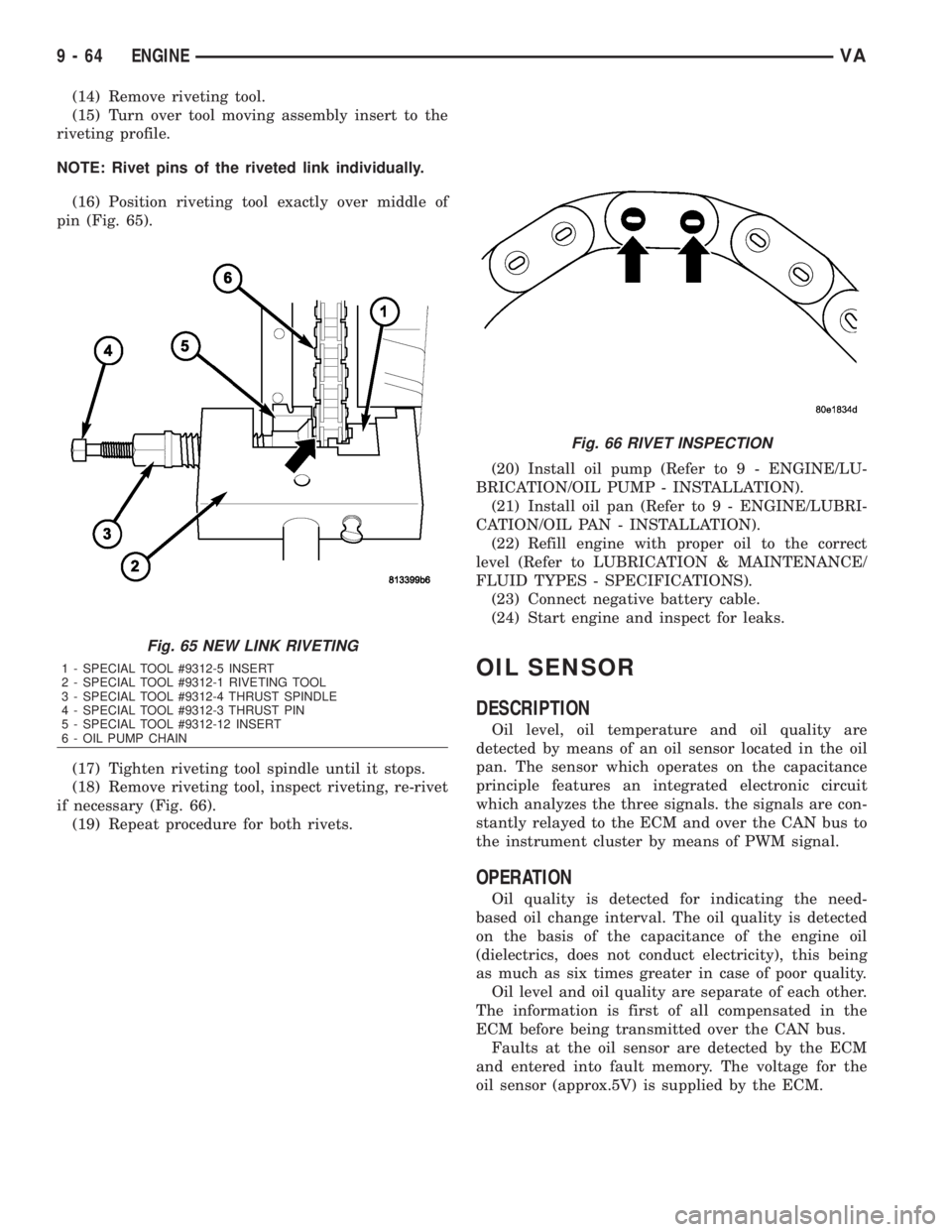
(16) Position riveting tool exactly over middle of
pin (Fig. 65).
(17) Tighten riveting tool spindle until it stops.
(18) Remove riveting tool, inspect riveting, re-rivet
if necessary (Fig. 66).
(19) Repeat procedure for both rivets.(20) Install oil pump (Refer to 9 - ENGINE/LU-
BRICATION/OIL PUMP - INSTALLATION).
(21) Install oil pan (Refer to 9 - ENGINE/LUBRI-
CATION/OIL PAN - INSTALLATION).
(22) Refill engine with proper oil to the correct
level (Refer to LUBRICATION & MAINTENANCE/
FLUID TYPES - SPECIFICATIONS).
(23) Connect negative battery cable.
(24) Start engine and inspect for leaks.
OIL SENSOR
DESCRIPTION
Oil level, oil temperature and oil quality are
detected by means of an oil sensor located in the oil
pan. The sensor which operates on the capacitance
principle features an integrated electronic circuit
which analyzes the three signals. the signals are con-
stantly relayed to the ECM and over the CAN bus to
the instrument cluster by means of PWM signal.
OPERATION
Oil quality is detected for indicating the need-
based oil change interval. The oil quality is detected
on the basis of the capacitance of the engine oil
(dielectrics, does not conduct electricity), this being
as much as six times greater in case of poor quality.
Oil level and oil quality are separate of each other.
The information is first of all compensated in the
ECM before being transmitted over the CAN bus.
Faults at the oil sensor are detected by the ECM
and entered into fault memory. The voltage for the
oil sensor (approx.5V) is supplied by the ECM.
Fig. 65 NEW LINK RIVETING
1 - SPECIAL TOOL #9312-5 INSERT
2 - SPECIAL TOOL #9312-1 RIVETING TOOL
3 - SPECIAL TOOL #9312-4 THRUST SPINDLE
4 - SPECIAL TOOL #9312-3 THRUST PIN
5 - SPECIAL TOOL #9312-12 INSERT
6 - OIL PUMP CHAIN
Fig. 66 RIVET INSPECTION
9 - 64 ENGINEVA
Page 1640 of 2305
REMOVAL
(1) Disconnect the negative battery cable.
(2) Raise and support the vehicle.
(3) Drain engine oil into a suitable, and appropri-
ately marked container.
(4) Remove engine mount to chassis nuts.
(5) Lower vehicle and install engine support.
(6) Remove the turbo charger heat shield to radia-
tor support bolts.
(7) Raise engine until the weight of the engine no
longer rests on the engine mounts.
(8) Raise and support the vehicle.
(9) Detach the front stabilizer bar at the front axle
and rotate it downward.
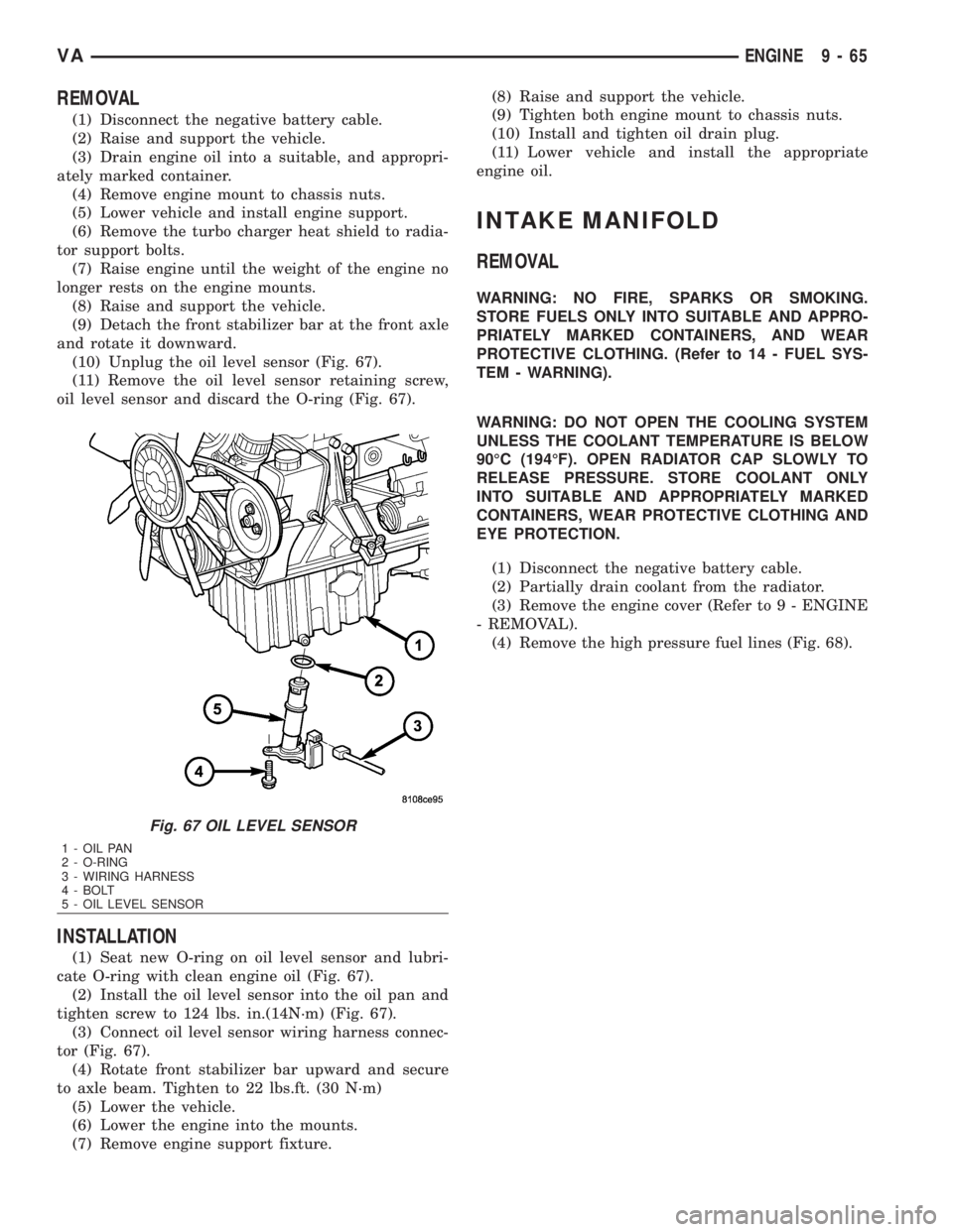
(10) Unplug the oil level sensor (Fig. 67).
(11) Remove the oil level sensor retaining screw,
oil level sensor and discard the O-ring (Fig. 67).
INSTALLATION
(1) Seat new O-ring on oil level sensor and lubri-
cate O-ring with clean engine oil (Fig. 67).
(2) Install the oil level sensor into the oil pan and
tighten screw to 124 lbs. in.(14N´m) (Fig. 67).
(3) Connect oil level sensor wiring harness connec-
tor (Fig. 67).
(4) Rotate front stabilizer bar upward and secure
to axle beam. Tighten to 22 lbs.ft. (30 N´m)
(5) Lower the vehicle.
(6) Lower the engine into the mounts.
(7) Remove engine support fixture.(8) Raise and support the vehicle.
(9) Tighten both engine mount to chassis nuts.
(10) Install and tighten oil drain plug.
(11) Lower vehicle and install the appropriate
engine oil.
INTAKE MANIFOLD
REMOVAL
WARNING: NO FIRE, SPARKS OR SMOKING.
STORE FUELS ONLY INTO SUITABLE AND APPRO-
PRIATELY MARKED CONTAINERS, AND WEAR
PROTECTIVE CLOTHING. (Refer to 14 - FUEL SYS-
TEM - WARNING).
WARNING: DO NOT OPEN THE COOLING SYSTEM
UNLESS THE COOLANT TEMPERATURE IS BELOW
90ÉC (194ÉF). OPEN RADIATOR CAP SLOWLY TO
RELEASE PRESSURE. STORE COOLANT ONLY
INTO SUITABLE AND APPROPRIATELY MARKED
CONTAINERS, WEAR PROTECTIVE CLOTHING AND
EYE PROTECTION.
(1) Disconnect the negative battery cable.
(2) Partially drain coolant from the radiator.
(3) Remove the engine cover (Refer to 9 - ENGINE
- REMOVAL).
(4) Remove the high pressure fuel lines (Fig. 68).
Fig. 67 OIL LEVEL SENSOR
1 - OIL PAN
2 - O-RING
3 - WIRING HARNESS
4 - BOLT
5 - OIL LEVEL SENSOR
VAENGINE 9 - 65
Page 1646 of 2305
INSTALLATION
CAUTION: Care must be taken to closley inspect
the gasket area around the time case cover to cyl-
inder head gasket coolant port. If damage is found,
replace the cylinder head gasket. Failure to do so
may result in engine damage.
NOTE: Thoroughly clean all mating surfaces with
the appropriate solvents to assure that no grease or
oil is present during assembly.
(1) Inspect cylinder head gasket and oil pan gas-
ket. If damaged, replace.
(2) Replace the front crankshaft seal (Refer to 9 -
ENGINE/ENGINE BLOCK/CRANKSHAFT OIL
SEAL - FRONT - INSTALLATION).
(3) Install ancillary components to timing case
cover.
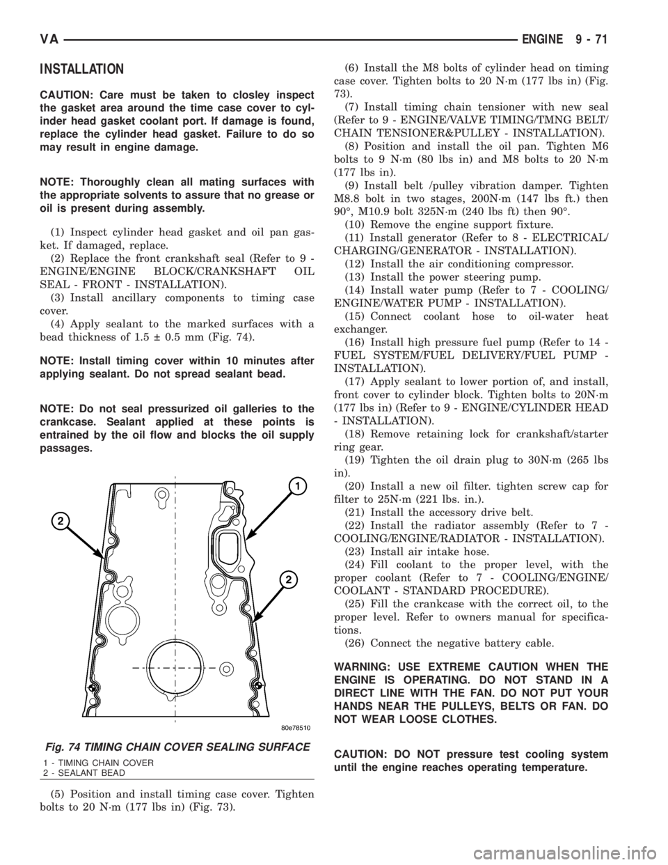
(4) Apply sealant to the marked surfaces with a
bead thickness of 1.5 0.5 mm (Fig. 74).
NOTE: Install timing cover within 10 minutes after
applying sealant. Do not spread sealant bead.
NOTE: Do not seal pressurized oil galleries to the
crankcase. Sealant applied at these points is
entrained by the oil flow and blocks the oil supply
passages.
(5) Position and install timing case cover. Tighten
bolts to 20 N´m (177 lbs in) (Fig. 73).(6) Install the M8 bolts of cylinder head on timing
case cover. Tighten bolts to 20 N´m (177 lbs in) (Fig.
73).
(7) Install timing chain tensioner with new seal
(Refer to 9 - ENGINE/VALVE TIMING/TMNG BELT/
CHAIN TENSIONER&PULLEY - INSTALLATION).
(8) Position and install the oil pan. Tighten M6
bolts to 9 N´m (80 lbs in) and M8 bolts to 20 N´m
(177 lbs in).
(9) Install belt /pulley vibration damper. Tighten
M8.8 bolt in two stages, 200N´m (147 lbs ft.) then
90É, M10.9 bolt 325N´m (240 lbs ft) then 90É.
(10) Remove the engine support fixture.
(11) Install generator (Refer to 8 - ELECTRICAL/
CHARGING/GENERATOR - INSTALLATION).
(12) Install the air conditioning compressor.
(13) Install the power steering pump.
(14) Install water pump (Refer to 7 - COOLING/
ENGINE/WATER PUMP - INSTALLATION).
(15) Connect coolant hose to oil-water heat
exchanger.
(16) Install high pressure fuel pump (Refer to 14 -
FUEL SYSTEM/FUEL DELIVERY/FUEL PUMP -
INSTALLATION).
(17) Apply sealant to lower portion of, and install,
front cover to cylinder block. Tighten bolts to 20N´m
(177 lbs in) (Refer to 9 - ENGINE/CYLINDER HEAD
- INSTALLATION).
(18) Remove retaining lock for crankshaft/starter
ring gear.
(19) Tighten the oil drain plug to 30N´m (265 lbs
in).
(20) Install a new oil filter. tighten screw cap for
filter to 25N´m (221 lbs. in.).
(21) Install the accessory drive belt.
(22) Install the radiator assembly (Refer to 7 -
COOLING/ENGINE/RADIATOR - INSTALLATION).
(23) Install air intake hose.
(24) Fill coolant to the proper level, with the
proper coolant (Refer to 7 - COOLING/ENGINE/
COOLANT - STANDARD PROCEDURE).
(25) Fill the crankcase with the correct oil, to the
proper level. Refer to owners manual for specifica-
tions.
(26) Connect the negative battery cable.
WARNING: USE EXTREME CAUTION WHEN THE
ENGINE IS OPERATING. DO NOT STAND IN A
DIRECT LINE WITH THE FAN. DO NOT PUT YOUR
HANDS NEAR THE PULLEYS, BELTS OR FAN. DO
NOT WEAR LOOSE CLOTHES.
CAUTION: DO NOT pressure test cooling system
until the engine reaches operating temperature.
Fig. 74 TIMING CHAIN COVER SEALING SURFACE
1 - TIMING CHAIN COVER
2 - SEALANT BEAD
VAENGINE 9 - 71
Page 1684 of 2305
(7) Connect a scan tool, select from Main Menu,
System Select, Engine, System Tests, Fuel Quantity
Test, Engine Cranking Test and follow the screen.
(8) After ten seconds, a maximum of 2.5 ml
(between2&3graduation lines) may be reached in
the inner vials. If the level has exceeded the 2.5 ml,
replace that affected cylinder's injector, clear the
memory using the scan tool, empty the test vials, and
retest.
RUNNING TEST
NOTE: If an injector is found to be out of specifica-
tion, repeat this test procedure after the injector
replacement. Hydraulic flow will take the path of
least resistance and multiple failures may be identi-
fied. Engine temperature must be above 80É C
(176ÉF) to perform the running test.
Perform this test with the engine at operating tem-
perature. This test will assist in determining a defec-
tive or internally leaking injector(s) is present by
measuring the amount of fuel return.
(1) Turn the ignition off.
(2) Remove the engine cover (Refer to 9 - ENGINE
- REMOVAL).
(3) Disconnect the fuel return hoses at the top of
the injectors.
(4) Pinch off the fuel return line at the banjo bolt
fitting of the fuel rail.
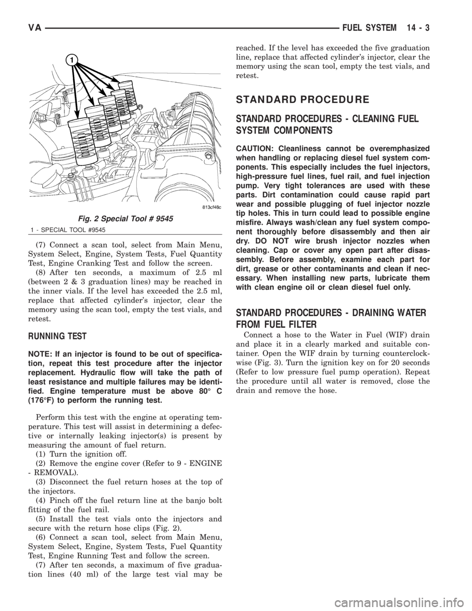
(5) Install the test vials onto the injectors and
secure with the return hose clips (Fig. 2).
(6) Connect a scan tool, select from Main Menu,
System Select, Engine, System Tests, Fuel Quantity
Test, Engine Running Test and follow the screen.
(7) After ten seconds, a maximum of five gradua-
tion lines (40 ml) of the large test vial may bereached. If the level has exceeded the five graduation
line, replace that affected cylinder's injector, clear the
memory using the scan tool, empty the test vials, and
retest.
STANDARD PROCEDURE
STANDARD PROCEDURES - CLEANING FUEL
SYSTEM COMPONENTS
CAUTION: Cleanliness cannot be overemphasized
when handling or replacing diesel fuel system com-
ponents. This especially includes the fuel injectors,
high-pressure fuel lines, fuel rail, and fuel injection
pump. Very tight tolerances are used with these
parts. Dirt contamination could cause rapid part
wear and possible plugging of fuel injector nozzle
tip holes. This in turn could lead to possible engine
misfire. Always wash/clean any fuel system compo-
nent thoroughly before disassembly and then air
dry. DO NOT wire brush injector nozzles when
cleaning. Cap or cover any open part after disas-
sembly. Before assembly, examine each part for
dirt, grease or other contaminants and clean if nec-
essary. When installing new parts, lubricate them
with clean engine oil or clean diesel fuel only.
STANDARD PROCEDURES - DRAINING WATER
FROM FUEL FILTER
Connect a hose to the Water in Fuel (WIF) drain
and place it in a clearly marked and suitable con-
tainer. Open the WIF drain by turning counterclock-
wise (Fig. 3). Turn the ignition key on for 20 seconds
(Refer to low pressure fuel pump operation). Repeat
the procedure until all water is removed, close the
drain and remove the hose.
Fig. 2 Special Tool # 9545
1 - SPECIAL TOOL #9545
VAFUEL SYSTEM 14 - 3
Page 1694 of 2305
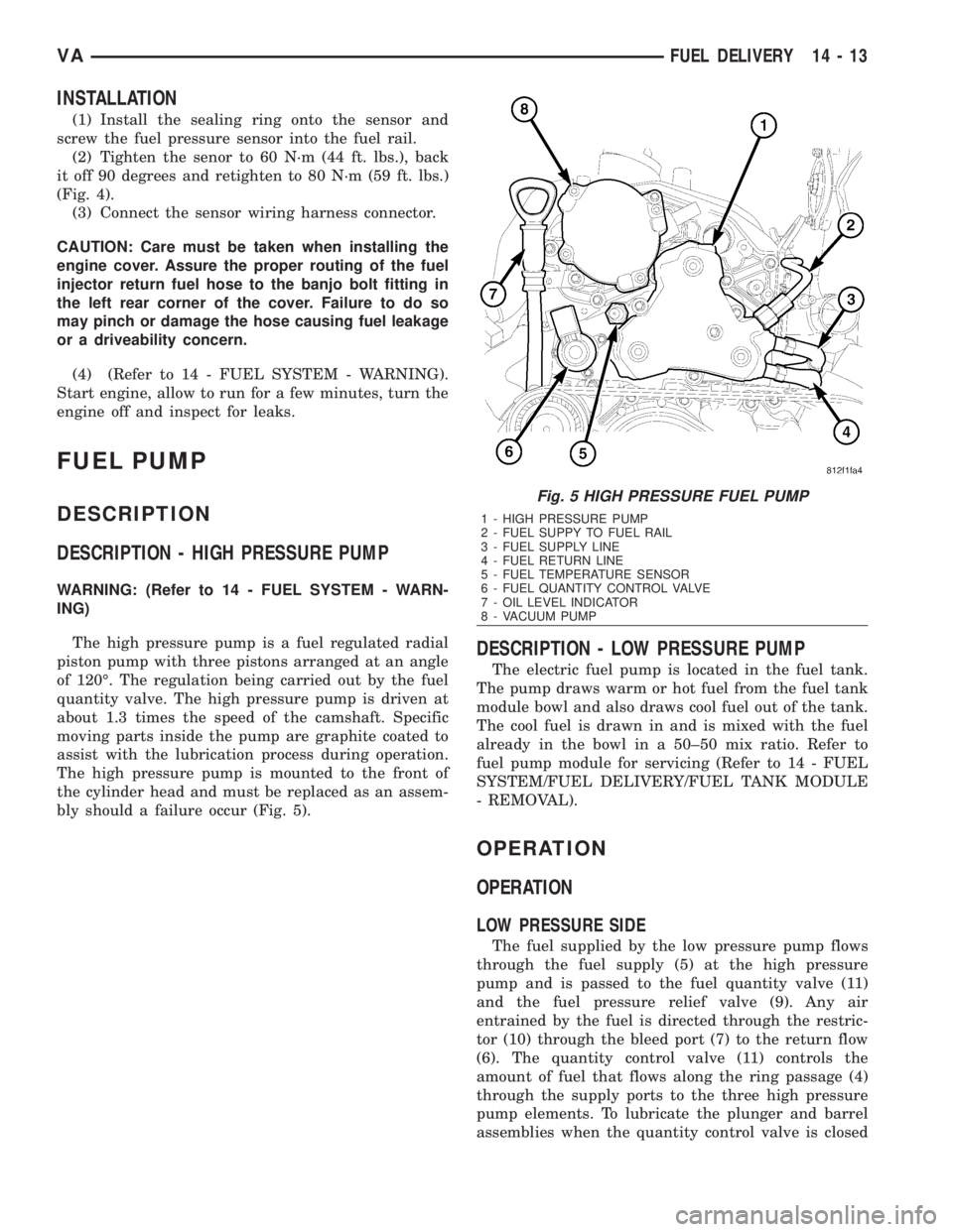
INSTALLATION
(1) Install the sealing ring onto the sensor and
screw the fuel pressure sensor into the fuel rail.
(2) Tighten the senor to 60 N´m (44 ft. lbs.), back
it off 90 degrees and retighten to 80 N´m (59 ft. lbs.)
(Fig. 4).
(3) Connect the sensor wiring harness connector.
CAUTION: Care must be taken when installing the
engine cover. Assure the proper routing of the fuel
injector return fuel hose to the banjo bolt fitting in
the left rear corner of the cover. Failure to do so
may pinch or damage the hose causing fuel leakage
or a driveability concern.
(4) (Refer to 14 - FUEL SYSTEM - WARNING).
Start engine, allow to run for a few minutes, turn the
engine off and inspect for leaks.
FUEL PUMP
DESCRIPTION
DESCRIPTION - HIGH PRESSURE PUMP
WARNING: (Refer to 14 - FUEL SYSTEM - WARN-
ING)
The high pressure pump is a fuel regulated radial
piston pump with three pistons arranged at an angle
of 120É. The regulation being carried out by the fuel
quantity valve. The high pressure pump is driven at
about 1.3 times the speed of the camshaft. Specific
moving parts inside the pump are graphite coated to
assist with the lubrication process during operation.
The high pressure pump is mounted to the front of
the cylinder head and must be replaced as an assem-
bly should a failure occur (Fig. 5).
DESCRIPTION - LOW PRESSURE PUMP
The electric fuel pump is located in the fuel tank.
The pump draws warm or hot fuel from the fuel tank
module bowl and also draws cool fuel out of the tank.
The cool fuel is drawn in and is mixed with the fuel
already in the bowl in a 50±50 mix ratio. Refer to
fuel pump module for servicing (Refer to 14 - FUEL
SYSTEM/FUEL DELIVERY/FUEL TANK MODULE
- REMOVAL).
OPERATION
OPERATION
LOW PRESSURE SIDE
The fuel supplied by the low pressure pump flows
through the fuel supply (5) at the high pressure
pump and is passed to the fuel quantity valve (11)
and the fuel pressure relief valve (9). Any air
entrained by the fuel is directed through the restric-
tor (10) through the bleed port (7) to the return flow
(6). The quantity control valve (11) controls the
amount of fuel that flows along the ring passage (4)
through the supply ports to the three high pressure
pump elements. To lubricate the plunger and barrel
assemblies when the quantity control valve is closed
Fig. 5 HIGH PRESSURE FUEL PUMP
1 - HIGH PRESSURE PUMP
2 - FUEL SUPPY TO FUEL RAIL
3 - FUEL SUPPLY LINE
4 - FUEL RETURN LINE
5 - FUEL TEMPERATURE SENSOR
6 - FUEL QUANTITY CONTROL VALVE
7 - OIL LEVEL INDICATOR
8 - VACUUM PUMP
VAFUEL DELIVERY 14 - 13
Page 1702 of 2305
FUEL QUANTITY CONTROL
VA LV E
DESCRIPTION
The fuel quantity control valve mounts to front of
the high pressure pump and is controlled by the
ECM. The quantity control valve assists in maintain-
ing proper fuel quantity injected under all operating
conditions. Fuel tank heat protection is also provided
by the quantity control valve. The valve meters the
exact amount of fuel to prevent excess heated fuel
from returning to the tank.
OPERATION
The ECM monitors the fuel system and measures
for pressure vibrations. The ECM will then send a
pulse width signal to the quantity control valve to
regulate the amount of fuel to the high pressure
pump plunger and barrel assemblies. The valve then
adjusts the injection correction quantity for each
individual cylinder in line with the firing order, there
by eliminating the pressure resonance in the fuel rail
and improving each independent injectors operation.
The fuel quantity valve also interrupts the fuel sup-
ply to the high pressure pump plunger and barrel
assemblies when the engine is switched off.
The ECM detects the operating state which exists
at the engine by means of the sensors. In order to
adapt the quantity injected, either the rail pressure
can be adjusted by way of the pressure regulator
valve and the quantity control valve, or the actuationtime of the solenoid valves in the fuel injectors can
be extended or shortened.
Fuel quantity control is performed under the fol-
lowing operating conditions:
²Approximately 30 seconds after the engine has
started
²Fuel temperature > 20ÉC (68ÉF)
²Engine not in deceleration mode
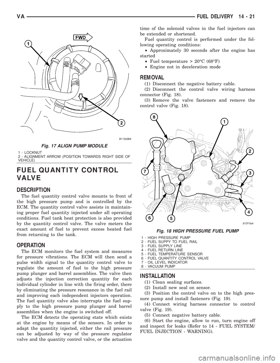
REMOVAL
(1) Disconnect the negative battery cable.
(2) Disconnect the control valve wiring harness
connector (Fig. 18).
(3) Remove the valve fasteners and remove the
control valve (Fig. 18).
INSTALLATION
(1) Clean sealing surfaces.
(2) Install new seal on sensor.
(3) Position the control valve on to the high pres-
sure pump and install fasteners (Fig. 19).
(4) Connect wiring harness connector to control
valve (Fig. 19).
(5) Connect negative battery cable.
(6) Start the engine, allow to run, turn engine off
and inspect for leaks (Refer to 14 - FUEL SYSTEM/
FUEL INJECTION - WARNING).
Fig. 17 ALIGN PUMP MODULE
1 - LOCKNUT
2 - ALIGNMENT ARROW (POSITION TOWARDS RIGHT SIDE OF
VEHICLE)
Fig. 18 HIGH PRESSURE FUEL PUMP
1 - HIGH PRESSURE PUMP
2 - FUEL SUPPY TO FUEL RAIL
3 - FUEL SUPPLY LINE
4 - FUEL RETURN LINE
5 - FUEL TEMPERATURE SENSOR
6 - FUEL QUANTITY CONTROL VALVE
7 - OIL LEVEL INDICATOR
8 - VACUUM PUMP
VAFUEL DELIVERY 14 - 21
Page 1704 of 2305
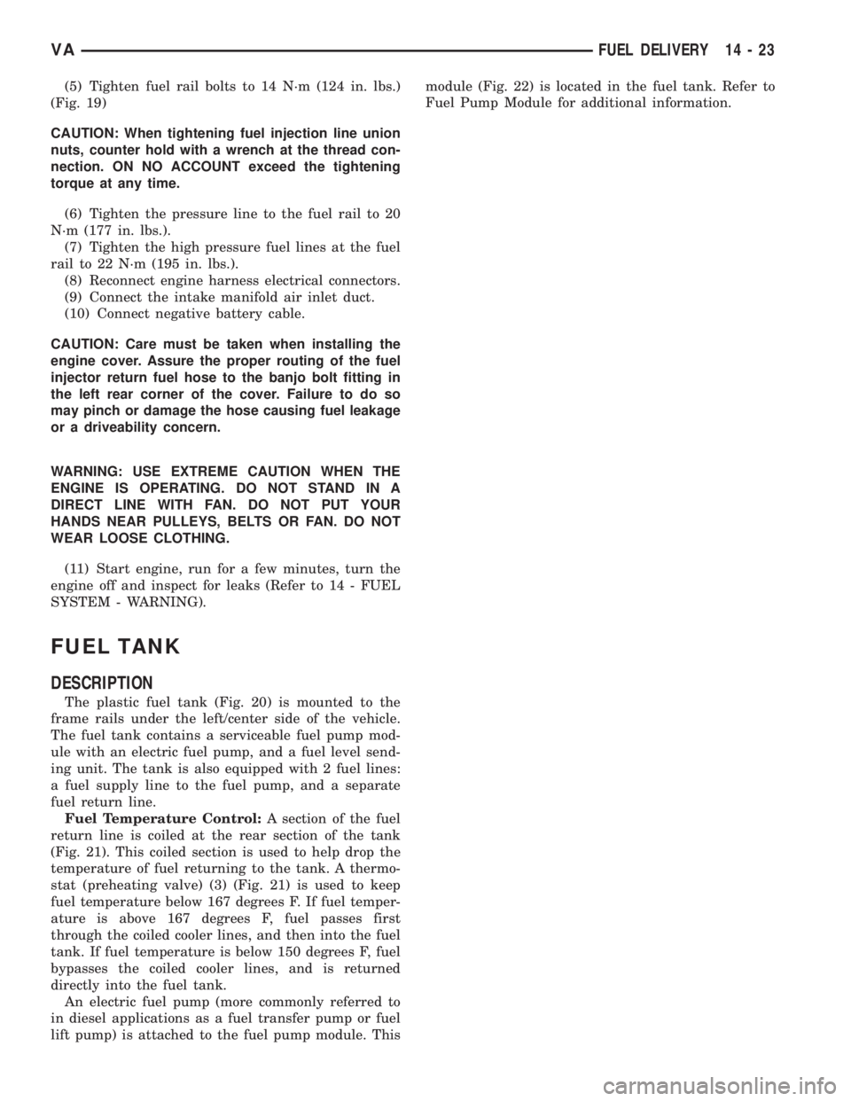
(5) Tighten fuel rail bolts to 14 N´m (124 in. lbs.)
(Fig. 19)
CAUTION: When tightening fuel injection line union
nuts, counter hold with a wrench at the thread con-
nection. ON NO ACCOUNT exceed the tightening
torque at any time.
(6) Tighten the pressure line to the fuel rail to 20
N´m (177 in. lbs.).
(7) Tighten the high pressure fuel lines at the fuel
rail to 22 N´m (195 in. lbs.).
(8) Reconnect engine harness electrical connectors.
(9) Connect the intake manifold air inlet duct.
(10) Connect negative battery cable.
CAUTION: Care must be taken when installing the
engine cover. Assure the proper routing of the fuel
injector return fuel hose to the banjo bolt fitting in
the left rear corner of the cover. Failure to do so
may pinch or damage the hose causing fuel leakage
or a driveability concern.
WARNING: USE EXTREME CAUTION WHEN THE
ENGINE IS OPERATING. DO NOT STAND IN A
DIRECT LINE WITH FAN. DO NOT PUT YOUR
HANDS NEAR PULLEYS, BELTS OR FAN. DO NOT
WEAR LOOSE CLOTHING.
(11) Start engine, run for a few minutes, turn the
engine off and inspect for leaks (Refer to 14 - FUEL
SYSTEM - WARNING).
FUEL TANK
DESCRIPTION
The plastic fuel tank (Fig. 20) is mounted to the
frame rails under the left/center side of the vehicle.
The fuel tank contains a serviceable fuel pump mod-
ule with an electric fuel pump, and a fuel level send-
ing unit. The tank is also equipped with 2 fuel lines:
a fuel supply line to the fuel pump, and a separate
fuel return line.
Fuel Temperature Control:A section of the fuel
return line is coiled at the rear section of the tank
(Fig. 21). This coiled section is used to help drop the
temperature of fuel returning to the tank. A thermo-
stat (preheating valve) (3) (Fig. 21) is used to keep
fuel temperature below 167 degrees F. If fuel temper-
ature is above 167 degrees F, fuel passes first
through the coiled cooler lines, and then into the fuel
tank. If fuel temperature is below 150 degrees F, fuel
bypasses the coiled cooler lines, and is returned
directly into the fuel tank.
An electric fuel pump (more commonly referred to
in diesel applications as a fuel transfer pump or fuel
lift pump) is attached to the fuel pump module. Thismodule (Fig. 22) is located in the fuel tank. Refer to
Fuel Pump Module for additional information.
VAFUEL DELIVERY 14 - 23
Page 1723 of 2305
²Tighten the nut to 60 N´m (44 ft. lbs.)
²Loosen the nut 90 degrees.
²Retighten the nut to 80 N´m (59 ft. lbs.).
(3) Install fuel rail (Refer to 14 - FUEL SYSTEM/
FUEL INJECTION/FUEL INJECTOR - INSTALLA-
TION).
(4) Connect negative battery cable.
(5) Start engine, allow to warm, turn engine off
and inspect for leaks (Refer to 14 - FUEL SYSTEM -
DIAGNOSIS AND TESTING).
FUEL TEMPERATURE SENSOR
DESCRIPTION
The fuel temperature sensor is integrated in the
high pressure fuel pump next to the fuel quantity
valve. The sensor detects the temperature of the fuel
and supplies that information to the ECM. The sen-
sor ranges from - 40ÉF (- 40C) to 284ÉF (140ÉC). If
the engine is cold, the actual value sent will read
ambient temperature. The value rises after the
engine has been started.
OPERATION
An negative temperature coefficient (NTC) resistor
integrated in the fuel temperature sensor alters it's
electrical resistance in line with the fuel temperature
(the resistance drops as the temperature rises). The
ECM uses this reading to calculate optimum engine
performance under all driving conditions. If the fuel
is to warm, the rail pressure in the system is low-
ered. The controller quantity of the pressure regulat-
ing valve is reduced and the fuel temperature is
lowered.
REMOVAL
NOTE: Capture and properly store all fluid seepage
in appropriately marked containers.
(1) Disconnect the negative battery cable.
(2) Remove the fuel temperature sensor from the
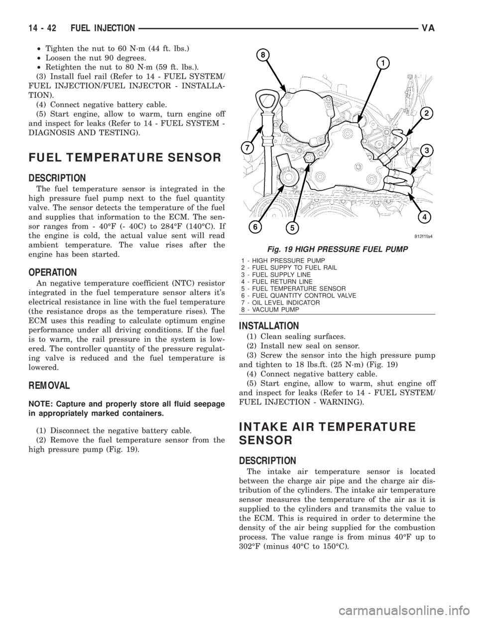
high pressure pump (Fig. 19).
INSTALLATION
(1) Clean sealing surfaces.
(2) Install new seal on sensor.
(3) Screw the sensor into the high pressure pump
and tighten to 18 lbs.ft. (25 N´m) (Fig. 19)
(4) Connect negative battery cable.
(5) Start engine, allow to warm, shut engine off
and inspect for leaks (Refer to 14 - FUEL SYSTEM/
FUEL INJECTION - WARNING).
INTAKE AIR TEMPERATURE
SENSOR
DESCRIPTION
The intake air temperature sensor is located
between the charge air pipe and the charge air dis-
tribution of the cylinders. The intake air temperature
sensor measures the temperature of the air as it is
supplied to the cylinders and transmits the value to
the ECM. This is required in order to determine the
density of the air being supplied for the combustion
process. The value range is from minus 40ÉF up to
302ÉF (minus 40ÉC to 150ÉC).
Fig. 19 HIGH PRESSURE FUEL PUMP
1 - HIGH PRESSURE PUMP
2 - FUEL SUPPY TO FUEL RAIL
3 - FUEL SUPPLY LINE
4 - FUEL RETURN LINE
5 - FUEL TEMPERATURE SENSOR
6 - FUEL QUANTITY CONTROL VALVE
7 - OIL LEVEL INDICATOR
8 - VACUUM PUMP
14 - 42 FUEL INJECTIONVA