2006 MERCEDES-BENZ SPRINTER oil level
[x] Cancel search: oil levelPage 1618 of 2305
(3) Install the retaining lock for the crankshaft/
ring gear.
NOTE: If the hub of the belt pulley/vibration damper
is tight, use a puller to remove it. Do Not tilt the
puller. The groves of the puller MUST mesh fully
into the slots of the belt pulley.
NOTE: Inspect the running surface of the belt pulley
for wear.
(4) Remove the belt pully/vibration damper.
CAUTION: Care must be taken to prevent severe
damage to the crankshaft and mounting whole for
the front crankshaft seal.
(5) Using a suitable prying tool, remove the front
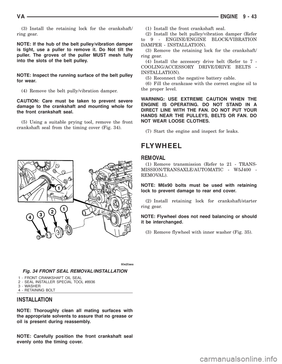
crankshaft seal from the timing cover (Fig. 34).
INSTALLATION
NOTE: Thoroughly clean all mating surfaces with
the appropriate solvents to assure that no grease or
oil is present during reassembly.
NOTE: Carefully position the front crankshaft seal
evenly onto the timing cover.(1) Install the front crankshaft seal.
(2) Install the belt pulley/vibration damper (Refer
to 9 - ENGINE/ENGINE BLOCK/VIBRATION
DAMPER - INSTALLATION).
(3) Remove the retaining lock for the crankshaft/
ring gear.
(4) Install the accessory drive belt (Refer to 7 -
COOLING/ACCESSORY DRIVE/DRIVE BELTS -
INSTALLATION).
(5) Reconnect the negative battery cable.
(6) Fill the crankcase with the correct engine oil to
the proper level.
WARNING: USE EXTREME CAUTION WHEN THE
ENGINE IS OPERATING. DO NOT STAND IN A
DIRECT LINE WITH THE FAN. DO NOT PUT YOUR
HANDS NEAR THE PULLEYS, BELTS OR FAN. DO
NOT WEAR LOOSE CLOTHES.
(7) Start the engine and inspect for leaks.
FLYWHEEL
REMOVAL
(1) Remove transmission (Refer to 21 - TRANS-
MISSION/TRANSAXLE/AUTOMATIC - W5J400 -
REMOVAL).
NOTE: M6x90 bolts must be used with retaining
lock to prevent damage to rear end cover.
(2) Install retaining lock for crankshaft/starter
ring gear.
NOTE: Flywheel does not need balancing or should
it be interchanged.
(3) Remove flywheel with inner washer (Fig. 35).
Fig. 34 FRONT SEAL REMOVAL/INSTALLATION
1 - FRONT CRANKSHAFT OIL SEAL
2 - SEAL INSTALLER SPECIAL TOOL #8936
3 - WASHER
4 - RETAINING BOLT
VAENGINE 9 - 43
Page 1626 of 2305
(9) Clean and inspect the connecting rod bolts.
CAUTION: Assure that the correct top and bottom
connecting rod bearings shells are used in accor-
dance with the markings.
CAUTION: The anti-twist locks of the connecting
rod bearing shells must be located in the slots of
the connecting rod bearing caps.
(10) Insert connecting rod bearing shell into con-
necting rod bearing cap.
CAUTION: The markings on the connecting rod and
connecting rod cap must be lined up.
(11) Install connecting rod bearing cap. Tighten
bolts in 3 stages, 5N´m (44 lbs in), 25N´m (221 lbs
in), 90É.
(12) Rotate crankshaft fully and check the clear-
ance.(13) Install oil pump (Refer to 9 - ENGINE/LU-
BRICATION/OIL PUMP - INSTALLATION).
(14) Install engine oil pan and oil pan drain plug
(Refer to 9 - ENGINE/LUBRICATION/OIL PAN -
INSTALLATION).
CAUTION: Install a cylinder head gasket of standard
thickness or a cylinder head gasket of repair thick-
ness depending on piston protrusion.
(15) Measure piston protrusion (Refer to 9 -
ENGINE/ENGINE BLOCK - STANDARD PROCE-
DURE).
(16) Install cylinder head (Refer to 9 - ENGINE/
CYLINDER HEAD - INSTALLATION).
(17) Install engine (Refer to 9 - ENGINE -
INSTALLATION).
(18) Fill the crankcase with correct engine oil, to
proper level. Refer to owners manual for specifica-
tions.
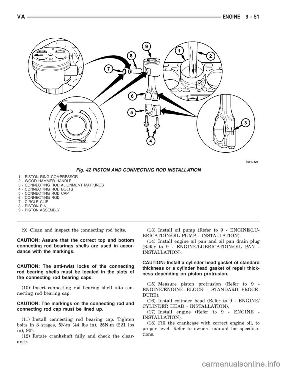
Fig. 42 PISTON AND CONNECTING ROD INSTALLATION
1 - PISTON RING COMPRESSOR
2 - WOOD HAMMER HANDLE
3 - CONNECTING ROD ALIGNMENT MARKINGS
4 - CONNECTING ROD BOLTS
5 - CONNECTING ROD CAP
6 - CONNECTING ROD
7 - CIRCLE CLIP
8 - PISTON PIN
9 - PISTON ASSEMBLY
VAENGINE 9 - 51
Page 1627 of 2305
(19) Fill the cooing system with proper coolant, to
the proper level (Refer to 7 - COOLING/ENGINE/
COOLANT - STANDARD PROCEDURE).
(20) Connect negative battery cable.
WARNING: USE EXTREME CAUTION WHEN THE
ENGINE IS OPERATING. DO NOT STAND IN A
DIRECT LINE WITH THE FAN. DO NOT PUT YOUR
HANDS NEAR THE PULLEYS, BELTS, OR FAN. DO
NOT WEAR LOOSE CLOTHES.
WARNING: (Refer to 14 - FUEL SYSTEM - WARN-
ING).
(21) Start the engine and inspect for leaks.
PISTON RINGS
STANDARD PROCEDURE - PISTON RING FIT-
TING
(1) Carefully clean the carbon from all ring
grooves. Oil drain openings in the oil ring groove and
pin boss must be clear. DO NOT remove metal from
the grooves or lands. This will change ring-to-groove
clearances and will damage the ring-to-land seating.
(2) Be sure the piston ring grooves are free of
nicks and burrs.
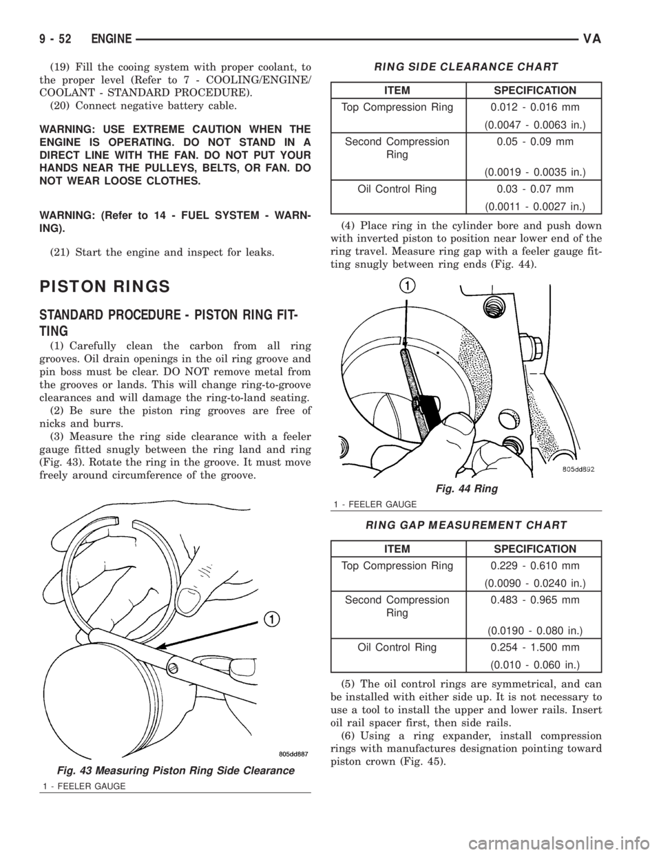
(3) Measure the ring side clearance with a feeler
gauge fitted snugly between the ring land and ring
(Fig. 43). Rotate the ring in the groove. It must move
freely around circumference of the groove.
RING SIDE CLEARANCE CHART
ITEM SPECIFICATION
Top Compression Ring 0.012 - 0.016 mm
(0.0047 - 0.0063 in.)
Second Compression
Ring0.05 - 0.09 mm
(0.0019 - 0.0035 in.)
Oil Control Ring 0.03 - 0.07 mm
(0.0011 - 0.0027 in.)
(4) Place ring in the cylinder bore and push down
with inverted piston to position near lower end of the
ring travel. Measure ring gap with a feeler gauge fit-
ting snugly between ring ends (Fig. 44).
RING GAP MEASUREMENT CHART
ITEM SPECIFICATION
Top Compression Ring 0.229 - 0.610 mm
(0.0090 - 0.0240 in.)
Second Compression
Ring0.483 - 0.965 mm
(0.0190 - 0.080 in.)
Oil Control Ring 0.254 - 1.500 mm
(0.010 - 0.060 in.)
(5) The oil control rings are symmetrical, and can
be installed with either side up. It is not necessary to
use a tool to install the upper and lower rails. Insert
oil rail spacer first, then side rails.
(6) Using a ring expander, install compression
rings with manufactures designation pointing toward
piston crown (Fig. 45).
Fig. 43 Measuring Piston Ring Side Clearance
1 - FEELER GAUGE
Fig. 44 Ring
1 - FEELER GAUGE
9 - 52 ENGINEVA
Page 1632 of 2305
INSTALLATION
(1) Clean all sealing surfaces.
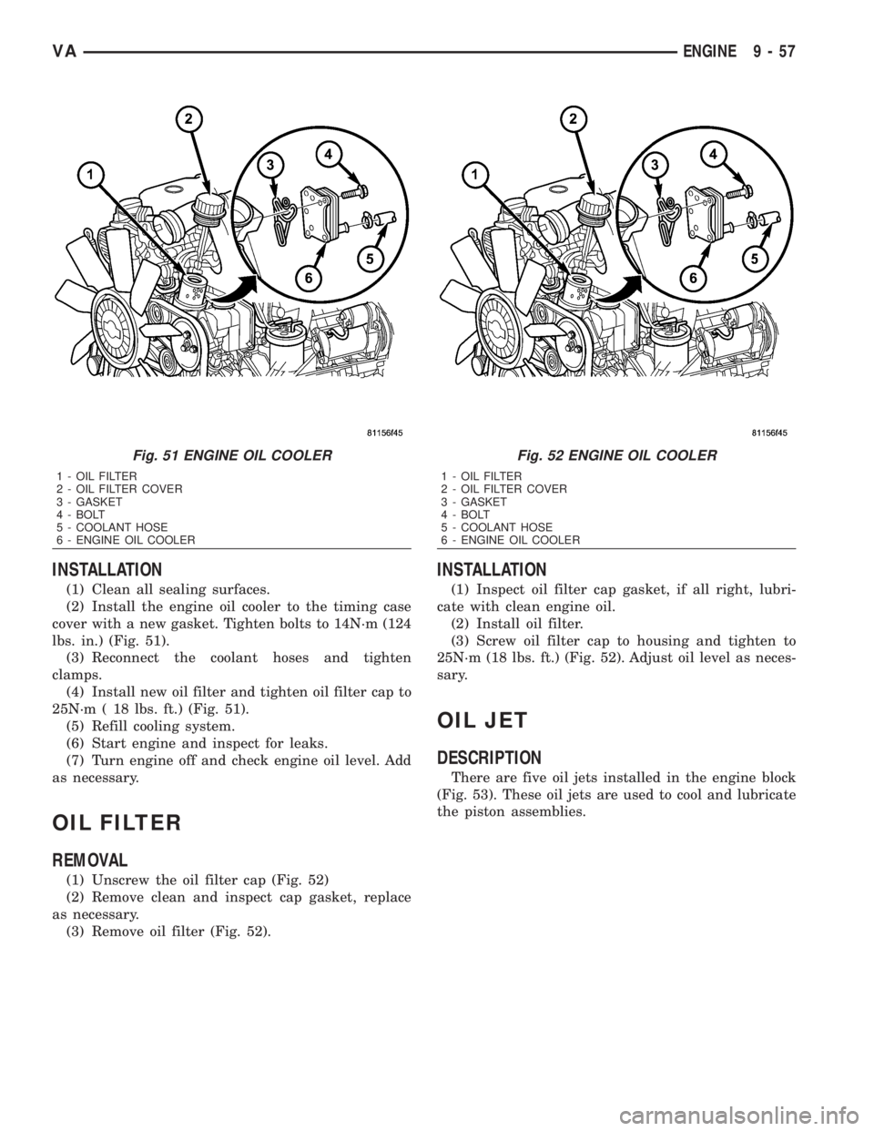
(2) Install the engine oil cooler to the timing case
cover with a new gasket. Tighten bolts to 14N´m (124
lbs. in.) (Fig. 51).
(3) Reconnect the coolant hoses and tighten
clamps.
(4) Install new oil filter and tighten oil filter cap to
25N´m ( 18 lbs. ft.) (Fig. 51).
(5) Refill cooling system.
(6) Start engine and inspect for leaks.
(7) Turn engine off and check engine oil level. Add
as necessary.
OIL FILTER
REMOVAL
(1) Unscrew the oil filter cap (Fig. 52)
(2) Remove clean and inspect cap gasket, replace
as necessary.
(3) Remove oil filter (Fig. 52).
INSTALLATION
(1) Inspect oil filter cap gasket, if all right, lubri-
cate with clean engine oil.
(2) Install oil filter.
(3) Screw oil filter cap to housing and tighten to
25N´m (18 lbs. ft.) (Fig. 52). Adjust oil level as neces-
sary.
OIL JET
DESCRIPTION
There are five oil jets installed in the engine block
(Fig. 53). These oil jets are used to cool and lubricate
the piston assemblies.
Fig. 51 ENGINE OIL COOLER
1 - OIL FILTER
2 - OIL FILTER COVER
3 - GASKET
4 - BOLT
5 - COOLANT HOSE
6 - ENGINE OIL COOLER
Fig. 52 ENGINE OIL COOLER
1 - OIL FILTER
2 - OIL FILTER COVER
3 - GASKET
4 - BOLT
5 - COOLANT HOSE
6 - ENGINE OIL COOLER
VAENGINE 9 - 57
Page 1634 of 2305
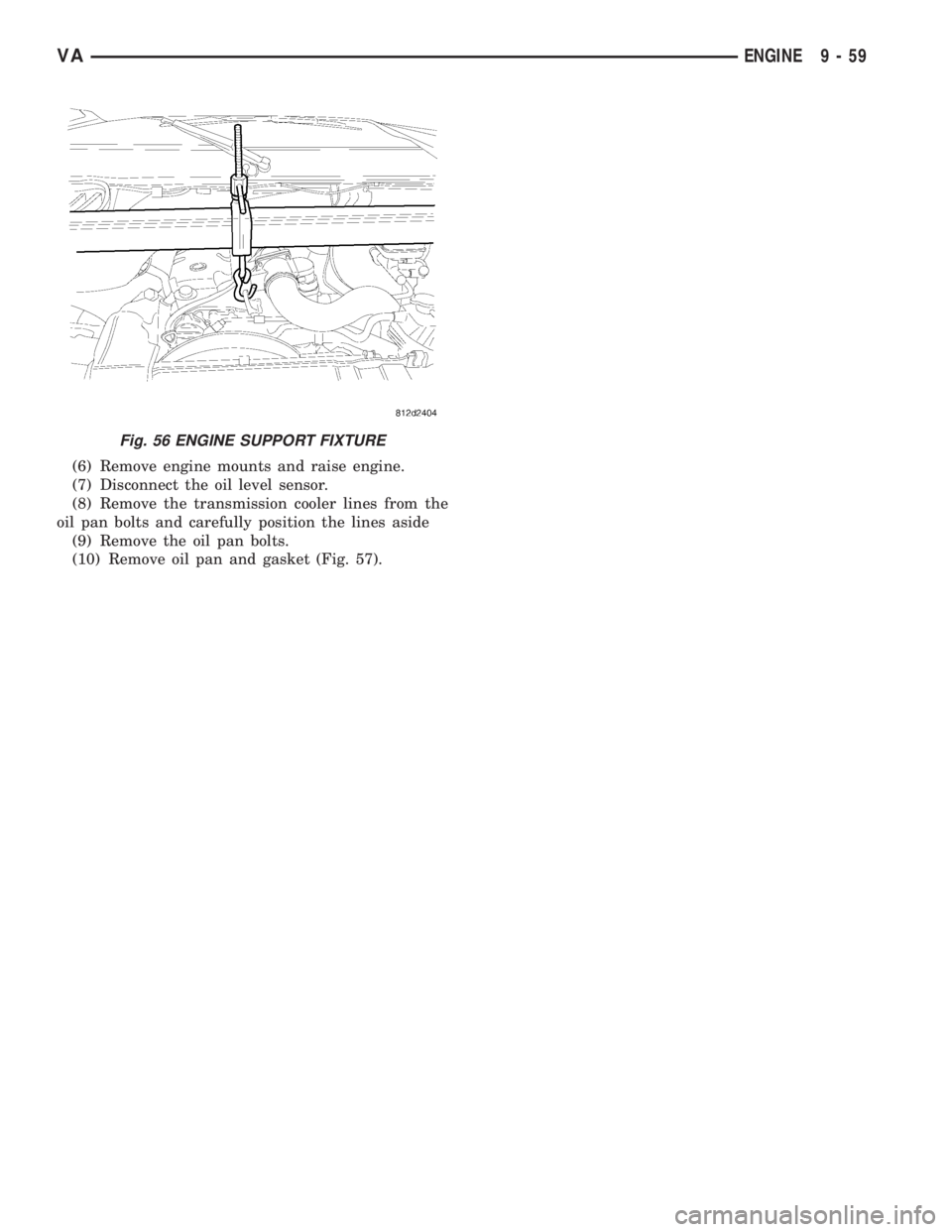
(6) Remove engine mounts and raise engine.
(7) Disconnect the oil level sensor.
(8) Remove the transmission cooler lines from the
oil pan bolts and carefully position the lines aside
(9) Remove the oil pan bolts.
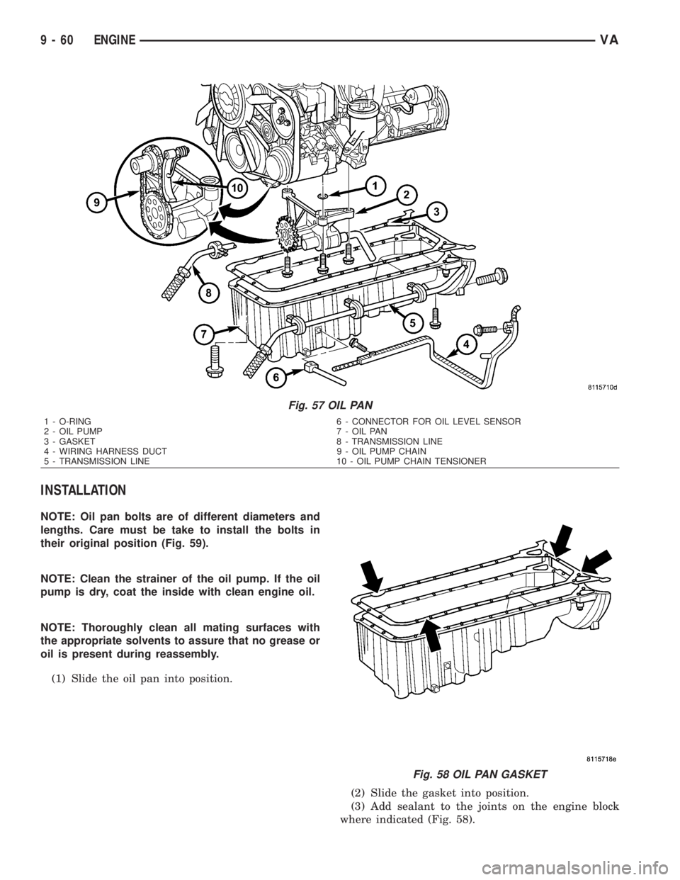
(10) Remove oil pan and gasket (Fig. 57).
Fig. 56 ENGINE SUPPORT FIXTURE
VAENGINE 9 - 59
Page 1635 of 2305
INSTALLATION
NOTE: Oil pan bolts are of different diameters and
lengths. Care must be take to install the bolts in
their original position (Fig. 59).
NOTE: Clean the strainer of the oil pump. If the oil
pump is dry, coat the inside with clean engine oil.
NOTE: Thoroughly clean all mating surfaces with
the appropriate solvents to assure that no grease or
oil is present during reassembly.
(1) Slide the oil pan into position.
(2) Slide the gasket into position.
(3) Add sealant to the joints on the engine block
where indicated (Fig. 58).
Fig. 57 OIL PAN
1 - O-RING 6 - CONNECTOR FOR OIL LEVEL SENSOR
2 - OIL PUMP 7 - OIL PAN
3 - GASKET 8 - TRANSMISSION LINE
4 - WIRING HARNESS DUCT 9 - OIL PUMP CHAIN
5 - TRANSMISSION LINE 10 - OIL PUMP CHAIN TENSIONER
Fig. 58 OIL PAN GASKET
9 - 60 ENGINEVA
Page 1636 of 2305
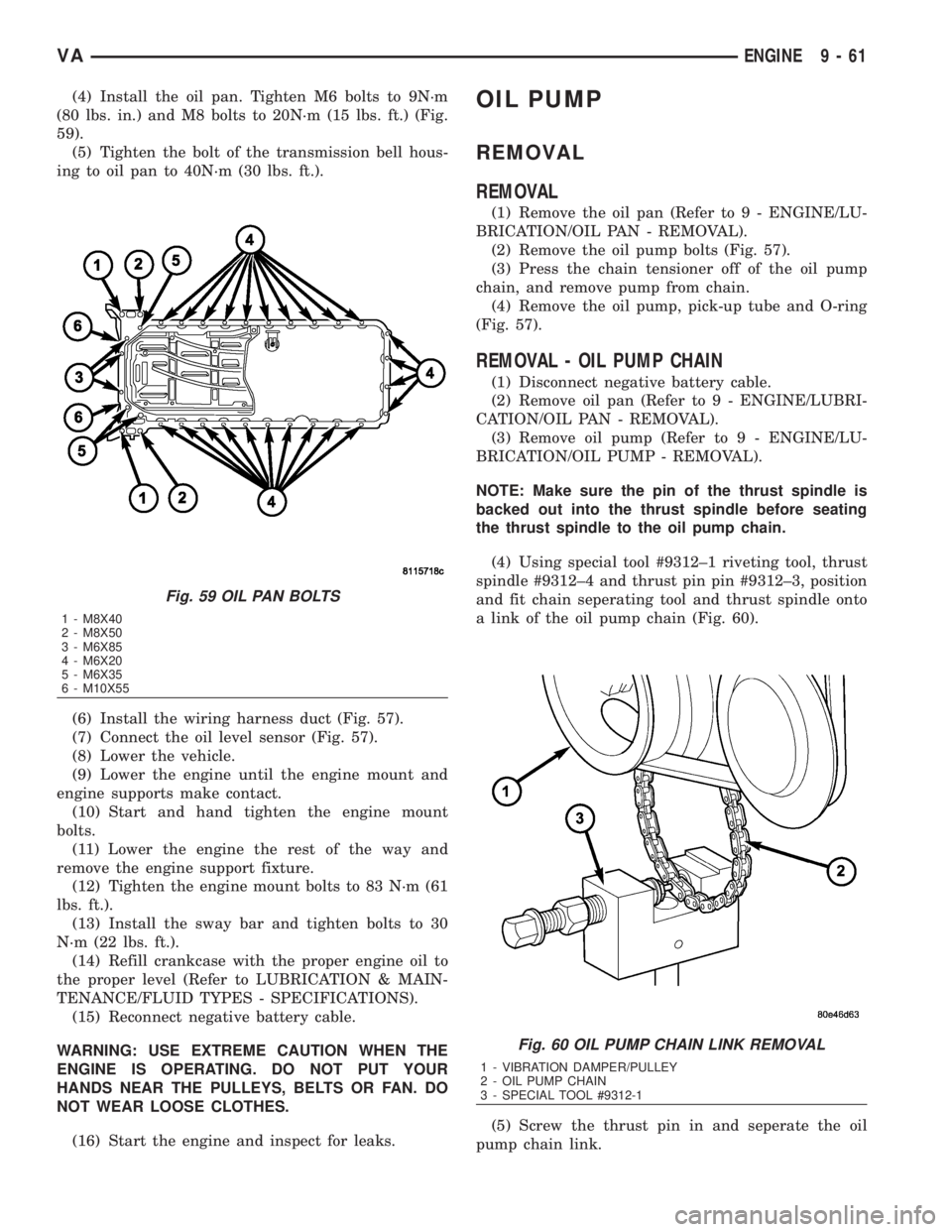
(4) Install the oil pan. Tighten M6 bolts to 9N´m
(80 lbs. in.) and M8 bolts to 20N´m (15 lbs. ft.) (Fig.
59).
(5) Tighten the bolt of the transmission bell hous-
ing to oil pan to 40N´m (30 lbs. ft.).
(6) Install the wiring harness duct (Fig. 57).
(7) Connect the oil level sensor (Fig. 57).
(8) Lower the vehicle.
(9) Lower the engine until the engine mount and
engine supports make contact.
(10) Start and hand tighten the engine mount
bolts.
(11) Lower the engine the rest of the way and
remove the engine support fixture.
(12) Tighten the engine mount bolts to 83 N´m (61
lbs. ft.).
(13) Install the sway bar and tighten bolts to 30
N´m (22 lbs. ft.).
(14) Refill crankcase with the proper engine oil to
the proper level (Refer to LUBRICATION & MAIN-
TENANCE/FLUID TYPES - SPECIFICATIONS).
(15) Reconnect negative battery cable.
WARNING: USE EXTREME CAUTION WHEN THE
ENGINE IS OPERATING. DO NOT PUT YOUR
HANDS NEAR THE PULLEYS, BELTS OR FAN. DO
NOT WEAR LOOSE CLOTHES.
(16) Start the engine and inspect for leaks.OIL PUMP
REMOVAL
REMOVAL
(1) Remove the oil pan (Refer to 9 - ENGINE/LU-
BRICATION/OIL PAN - REMOVAL).
(2) Remove the oil pump bolts (Fig. 57).
(3) Press the chain tensioner off of the oil pump
chain, and remove pump from chain.
(4) Remove the oil pump, pick-up tube and O-ring
(Fig. 57).
REMOVAL - OIL PUMP CHAIN
(1) Disconnect negative battery cable.
(2) Remove oil pan (Refer to 9 - ENGINE/LUBRI-
CATION/OIL PAN - REMOVAL).
(3) Remove oil pump (Refer to 9 - ENGINE/LU-
BRICATION/OIL PUMP - REMOVAL).
NOTE: Make sure the pin of the thrust spindle is
backed out into the thrust spindle before seating
the thrust spindle to the oil pump chain.
(4) Using special tool #9312±1 riveting tool, thrust
spindle #9312±4 and thrust pin pin #9312±3, position
and fit chain seperating tool and thrust spindle onto
a link of the oil pump chain (Fig. 60).
(5) Screw the thrust pin in and seperate the oil
pump chain link.
Fig. 59 OIL PAN BOLTS
1 - M8X40
2 - M8X50
3 - M6X85
4 - M6X20
5 - M6X35
6 - M10X55
Fig. 60 OIL PUMP CHAIN LINK REMOVAL
1 - VIBRATION DAMPER/PULLEY
2 - OIL PUMP CHAIN
3 - SPECIAL TOOL #9312-1
VAENGINE 9 - 61
Page 1637 of 2305
(6) Remove pressed - out oil pump chain pin from
chain seperation tool.
CAUTION: IT IS ESSENTIAL that the installation pro-
cedure for the oil pump chain is followed exactly.
Failure to do so will result in severe engine dam-
age.
INSTALLATION
INSTALLATION
NOTE: If the oil pump is dry, fill it with clean engine
oil before installation. Clean the oil pick±up tube
and strainer.
(1) Clean all sealing surfaces.
(2) Position the oil pump onto the drive chain and
reset tensioner.
(3) Install oil pump retaining bolts and tighten to
18 N´m (160 lbs. in.).
(4) Install the oil pan (Refer to 9 - ENGINE/LU-
BRICATION/OIL PUMP - INSTALLATION).
(5) Refill the crankcase to the appropriate level
with the proper engine oil (Refer to LUBRICATION
& MAINTENANCE/FLUID TYPES - SPECIFICA-
TIONS).
WARNING: USE EXTREME CAUTION WHEN THE
ENGINE IS OPERATING. DO NOT PUT YOUR
HANDS NEAR THE PULLEYS, BELTS OR FAN. DO
NOT WEAR LOOSE CLOTHES.
(6) Start the vehicle and inspect for leaks.
INSTALLATION - OIL PUMP CHAIN
CAUTION: IT IS ESSENTIAL that the installation pro-
cedure is followed exactly. Failure to do so will
result in severe engine damage.
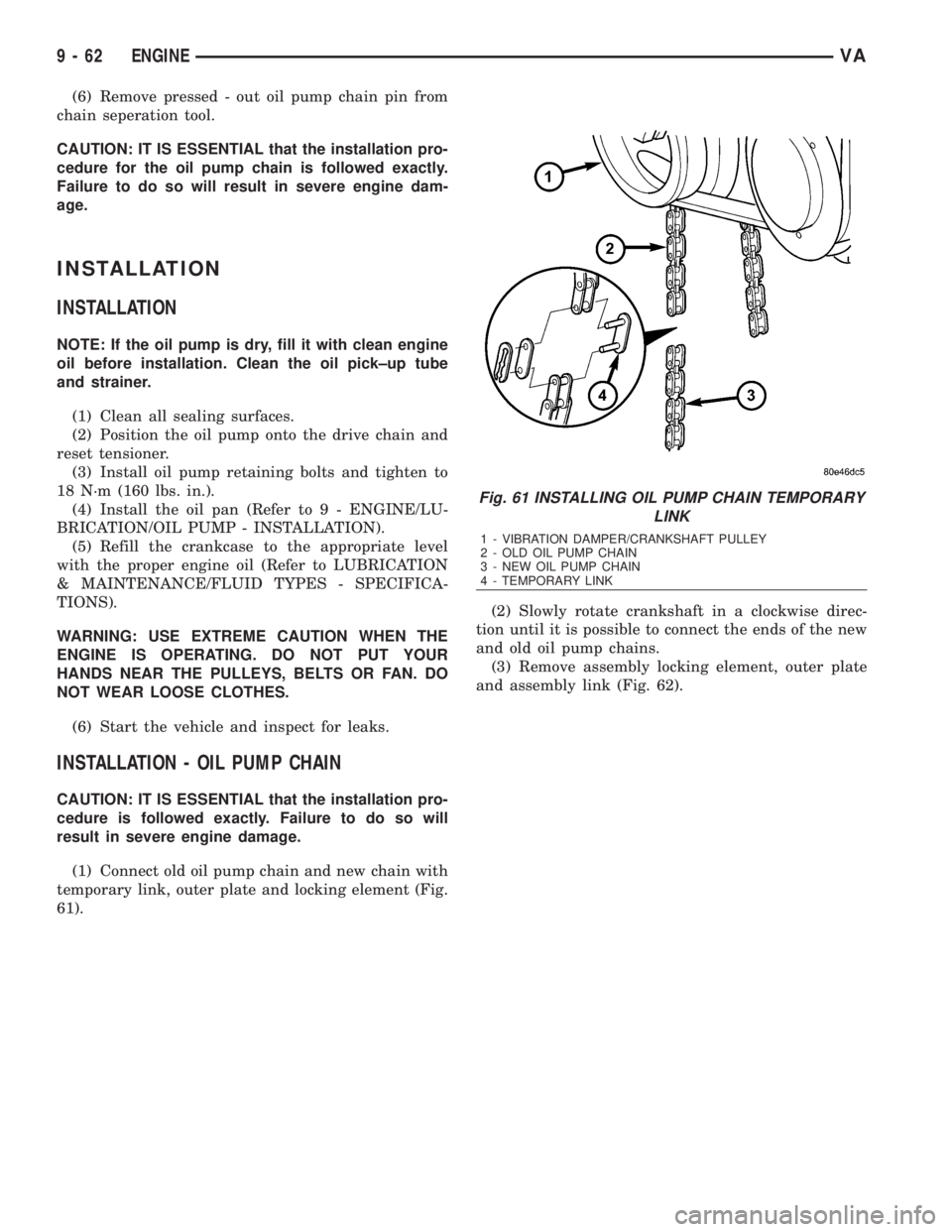
(1) Connect old oil pump chain and new chain with
temporary link, outer plate and locking element (Fig.
61).(2) Slowly rotate crankshaft in a clockwise direc-
tion until it is possible to connect the ends of the new
and old oil pump chains.
(3) Remove assembly locking element, outer plate
and assembly link (Fig. 62).
Fig. 61 INSTALLING OIL PUMP CHAIN TEMPORARY
LINK
1 - VIBRATION DAMPER/CRANKSHAFT PULLEY
2 - OLD OIL PUMP CHAIN
3 - NEW OIL PUMP CHAIN
4 - TEMPORARY LINK
9 - 62 ENGINEVA